A signed copy of the Certificate of Approval is available from the School of Graduate and Postdoctoral Studies. To improve the performance of the autonomous AV, the design synthesis is formulated as a two-layer design optimization problem. This is a true copy of the thesis, including any necessary final revisions as accepted by my examiners.
Yu, J., Sharma, T., and He, Y., "Design optimization of autonomous steering control schemes for articulated vehicles", Proceedings of the Canadian Society for Mechanical Engineering (CSME) International Congress 2021, June Charlottetown , PE, Canada .
- Motivation
- Problem statement
- Objective
- Organization
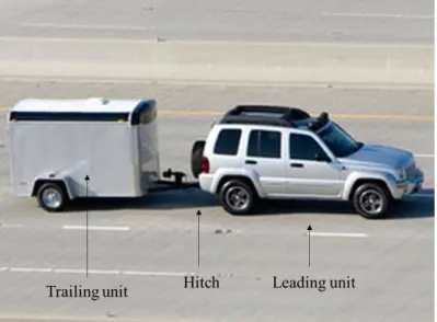
Path following is one of the core issues in the development of autonomous vehicles, which control the vehicle's movement to achieve the desired reference trajectory. To the author's knowledge, the motion planning and tracking control modules in the design of autonomous driving systems for AVs and SUVs are often built on the given vehicle mechanical system. To evaluate the applicability and effectiveness of the proposed approach, it is applied to the design synthesis of a CT combination with automated control.
Simulation results demonstrate the applicability and effectiveness of the proposed design synthesis approach in improving path-following performance within corresponding constraints in SLC maneuvers.
- Introduction
- The state-of-the-art of vehicle modeling, validating and stochastic methods
- The state-of-the-art of autonomous driving features
- The state-of-the-art of studies on articulated vehicle stability characteristics
- The state-of-the-art of design optimization
- Summary
In recent years, active safety features, including autonomous driving, have been developed and commercialized on SUVs to improve vehicle stability and safety. Autonomous obstacle-avoidance strategies for CT systems have been evaluated based on nonlinear vehicle models [66]. Based on the aforementioned literature review, a lot of research has been conducted on improving AV stability by mathematical dynamic model analysis, vehicle design optimization, and active safety system development.
Most autonomous driving strategies and active safety features are designed for SUVs and cannot simply be transferred to AVs.
Introduction
CT modeling and validation
- CarSim nonlinear CT model
- Validation
- Nonlinear TruckSim 21-DOF tractor-semitrailer model
- Validation
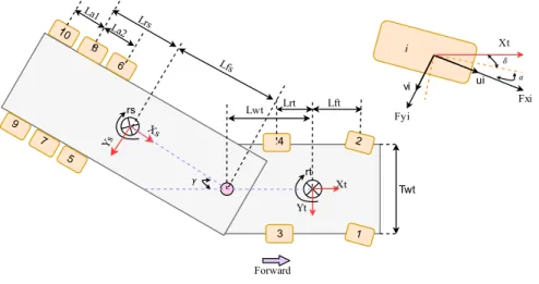
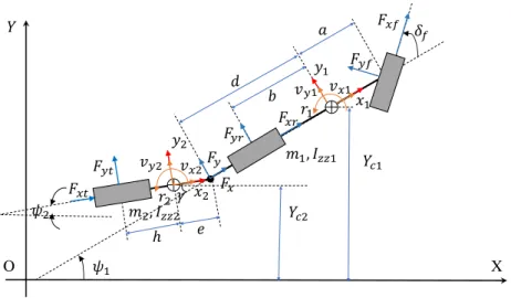
The pitch, bounce and roll motions of the car and trailer, and the aerodynamic forces are ignored [31]. As shown in Figure 3.6, this is the time history of the tire slip angle during the simulation. The longitudinal movement of the tractor, the lateral movement of the tractor, the yaw of the tractor and the articulation movement are 4 of the DOFs.
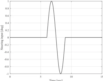
The first open-loop test scenario is a high-speed SLC maneuver where the longitudinal speed is constant and the steering angle of the tractor's front wheels is shown in Figure 3.10. The simulation has been performed at both high speed (90 km/h) and low speed (50 km/h) and the control inputs are the same. As shown, both the TruckSim model and the proposed nonlinear model show sine waveform laterally.
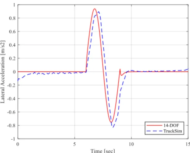
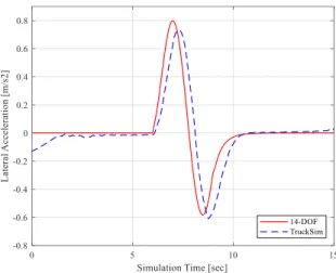
As the simulation starts, the TruckSim model presented non-zero lateral acceleration, which is due to the sophisticated tire model used in the TruckSim model, which also takes into account the lean angle of the tractor. The TruckSim model presents a larger peak value than that of the proposed model at that time around 9 seconds. As shown in the Figure 3.13 which shows the yaw rate time history of both the tractor and the.
The overall simulation results illustrate a good agreement between the 14-DOF nonlinear model and the TruckSim model. The lateral acceleration change of the TruckSim model is also slower than the 14-DOF model, which is due to the.
Summary
- Introduction
- Eigenvalue analysis
- Stochastic method
- Introduction
- Simulation environment
- Results
- Summary
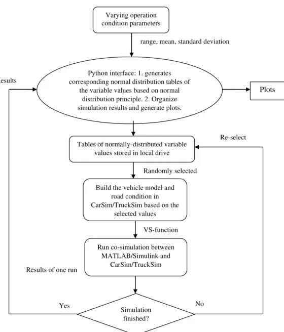
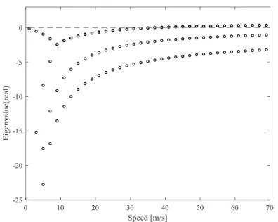
According to the mathematical description of the 3-DOF model in Equation (3-19), the system matrix can be expressed as As shown in Figure 4.1, which represents the real part of the eigenvalue, the image part of the eigenvalue is nonzero, which was not plotted here. Then, a comprehensive platform developed in Python will generate a complete lookup table of various working conditions.
After one run of the simulation is completed, the measured output, such as lateral acceleration and yaw rates, is saved to a local file. The selected dynamic responses related to the dual stability of the B-Train are the peak value of the lateral acceleration of the second trailer, trajectories of the system and the RWA ratio. The RWA is one of the recognized measurements to demonstrate the lateral stability of double light commercial vehicles with A/B trains.
While the coefficient of friction is lower than 0.5, part of the trailer 'takes off' from the road and is. Interestingly, the lateral acceleration of the tractor actually increases gradually with the coefficient of friction of the road surface and high lateral. In Run 44, the road condition is good and the road friction coefficient is high, although the rocking motion of the other trailer still exists, its amplitude is much smaller compared to Runs 5 and 28.
The critical speed of the 3-DOF model has been determined and will be considered in the development of the model-based controller. A comprehensive numerical simulation platform has been developed that focuses on modeling various road and load conditions of vehicle systems, including CTs and LCVs.
- Introduction
- MPC
- Introduction
- Problem formulation and constraint
- PSO and DE optimization algorithms
- Introduction
- PSO formulation
- DE formulation
- Overall Bi-layer optimization method
- Introduction
- Implementation
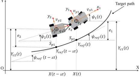
To complete the path following task: In this study, the measured output for this controller is 𝑌𝑐1 and 𝑌𝑐2, which is the global lateral position of the car and trailer, respectively. The horizontal coordinates of the car and the trailer in the inertial coordinate system are denoted as 𝑋(𝑡) and 𝑋(𝑡 − ∆𝜏), where the time delay ∆𝜏 is determined as Equation 5.11. As shown in Figure 5.1, at time 𝑡, the target points to be tracked by the center of gravity of the car and the trailer are indicated by points 𝑆𝑝1 and 𝑆𝑝2 on the target path, respectively.
It is assumed that GPS (Global Positioning System) data is provided in this CT system, which means that the measured result of the MPC controller can be defined as the lateral position of the car 𝑌𝑐1 and the lateral position of the trailer 𝑌𝑐2. As shown in Figure 5.1, the lateral track errors of the car and trailer can be determined by The first sum is the path tracking error, which is described by the deviation of the predicted outputs 𝒀(𝑘) from the desired output 𝒀𝒅(𝑘).
By solving the optimization problem defined in Equation (5.14), we obtain the solution in terms of the optimal control input increments evaluated at the sampling step k for the currently observed vehicle state vector 𝒙(𝑘), and denote the optimally predicted control input increments by . Two metaheuristic methods, namely PSO and DE are implemented and tested to find the world-best solution of the entire system. Over the SLC maneuver, the LMPC controller calculates the steering angle 𝛿𝑓 of the CT plant to track the reference path at a constant speed.
After completing the SLC maneuver corresponding to each of the n design variable sets, a fitness value vector in the form of [𝑓𝑃𝑆𝑂/𝐷𝐸(𝑋𝐷_0), 𝑓𝑃𝑆𝑂/𝐷, 𝑓𝑃𝑆𝑂/𝐷𝐸(𝑋𝐷_𝑛−1) ) ]𝑇 is reached. In the design optimization, the evaluations of the performance measures specified by Equations are obtained based on the dynamic responses of the CT over the simulated SLC maneuver.
Introduction
Testing setup
- Testing maneuvers
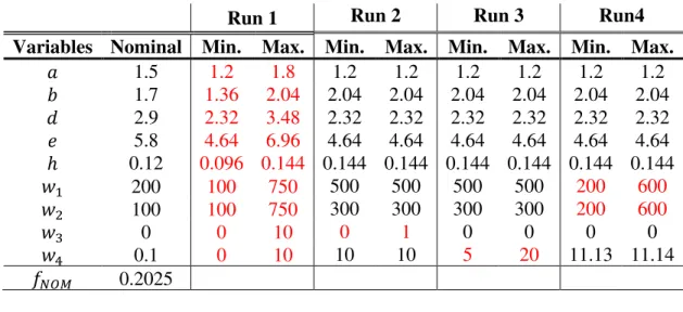
- Optimization parameters and nominal values
As discussed in Section 5.3, the parameters of PSO and DE need to be specified, and for this test the algorithm parameters are summarized in Table 6.2. The population has been set to 50 individuals in this test, and the termination criterion is maximum generation equal to 30. The inertia weight factor is set uniformly decreasing at a constant rate from 0.95 at the first generation to 0.3 of the last generation.
Results
- Performance improvement
- Effects of design variables
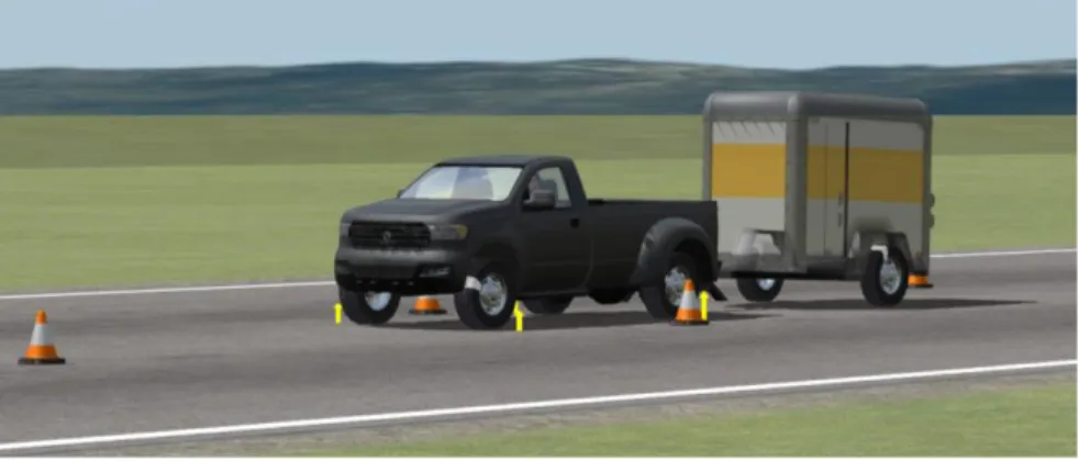
To examine the optimal design, we compare its performance measures with the baseline model counterparts. In the co-simulations, the CarSim model plays the role of the CT plant shown in Figure 5.2. Figures 6.1 and 6.2 show the reference road and car and trailer trajectories, respectively, for both the baseline and optimal models.
Figures 6.3 and 6.4 illustrate the time histories of the lateral acceleration of the car and the trailer, for both the base and optimal designs. Interestingly, the trailer lateral acceleration curve of the basic design shown in Figure 6.5 appears smooth, with no similar peaks in the corresponding car lateral acceleration curve shown in Figure 6.3. With four runs of the two-level optimization design shown in Figure 5.4, both search algorithms.
The weight represented by 𝑤4 penalizes the increase in the steering angle input of the car's front wheel, i.e. ∆𝛿𝑓. As can be seen from the figure, an increase in the value of e leads to a decrease in the overshoot. Close observation of the non-linear curve shown in Figure 6.14 reveals that within the range of variation of 𝑤1, the total 𝐽𝑃𝐹𝑂𝑇1 decreases with variable design.
The effect of the steering of the front wheels of the car due to the optimal LMPC controller on the lateral dynamics of the trailer is limited. The successful performance of design optimization demonstrates the effectiveness of the proposed design synthesis shown in Figure 5.3.
- Articulated vehicle modeling and analysis
- Optimization design synthesis for CT autonomous steering control
- Potential application of proposed strategies
- Future work
The detailed analysis of the articulated vehicle system on lateral stability was performed by linear and non-linear modeling methods. When the tire slip angle is large, an error can be expected from the linear tire model. To evaluate the applicability and effectiveness of the proposed method, it is applied to the design optimization of a car-trailer combination with an automatic steering system.
The optimal CT design derived from this study implies that to greatly improve high-speed road following performance and lateral stability for both the leading and following vehicle units, the proposed autonomous driving scheme must be integrated with an active trailer steering technique. . Possible applications of the stochastic modeling method could be the implementation in the machine trend model or the design of the adaptive-MPC controller. The potential application of design synthesis for simultaneously optimizing vehicle design and controller design can be extensive.
One of the future studies in this direction could be the integration of the hardware-in-the-loop (HIL) simulation method to further validate the optimized MPC controller. Sponsored by the Automotive Division of the Institution of Mechanical Engineers under the partnership of the International Federation of Societies d'Ingenieurs des Techniques de l'Automobile (FISITA) h (No. C132/83). He, “An Overview of Core Technologies for Autonomous and Semi-Autonomous Heavy-Duty Articulated Vehicles,” in Proceedings of the Canadian Society for Mechanical Engineering International Congress 2020, June Charlottetown, PE, Canada.
Sponsored by the Automobile Division of the Institution of Mechanical Engineers under the patronage of Federation Internationale des Societies d'Ingenieurs des Techniques de l'Automobile (FISITA) h 1983 (No. C132/83). Eberhart, “Empirical study of particle swarm optimization,” in Proceedings of the 1999 Congress on Evolutionary Computation, pp.