List of Appendices
List of Acronyms
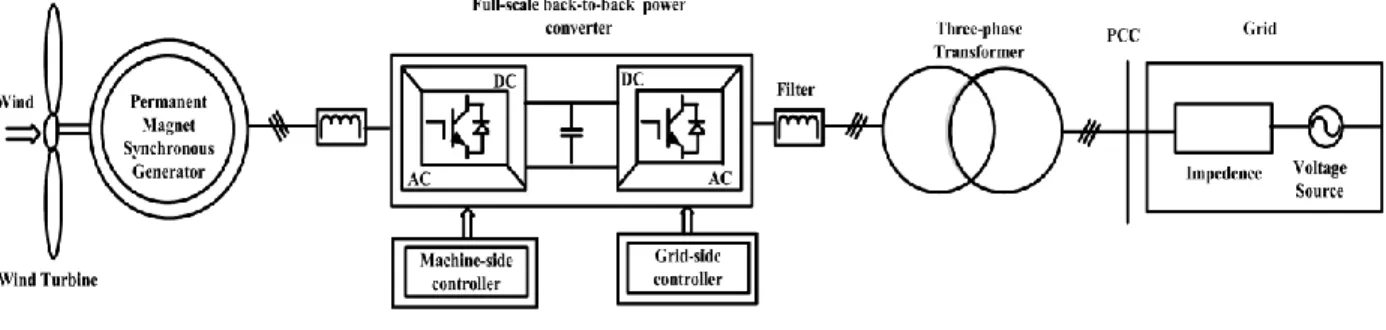
Introduction
- Background
- Features of modular design .1 Benefits of modular design
- Extent of local control in modular design
- Literature review about switch interleaving
- Benefits of interleaving
- Various applications of switch interleaving
- Implementation of interleaving in modular converter system
- Research objectives
- Thesis outline
As in the case of DC-DC converters, the use of interleaving in three-phase AC converters and its effect on system harmonics has been the subject of many publications. A systematic analysis of interleaving effects in three-phase VSCs was the subject of a study in [12]. The interlocking operation of the parallel three-phase VSC helps to design a system that uses smaller EMI filters and DC-link components [13].
The implementation of automatic interleaving is discussed with reference to three-phase VSC in the case of [6]. The main objective of this research work is to develop an interleaving control algorithm that promotes a decentralized control structure, unlike the common technique used for interleaving three-phase parallel converters. The varying nature of AC signals will make the application of these techniques very difficult in the case of three-phase voltage source converters.
Controller for automatic interleaving of parallel three-phase VSC will be the subject of discussion in Chapter 3.
- Introduction
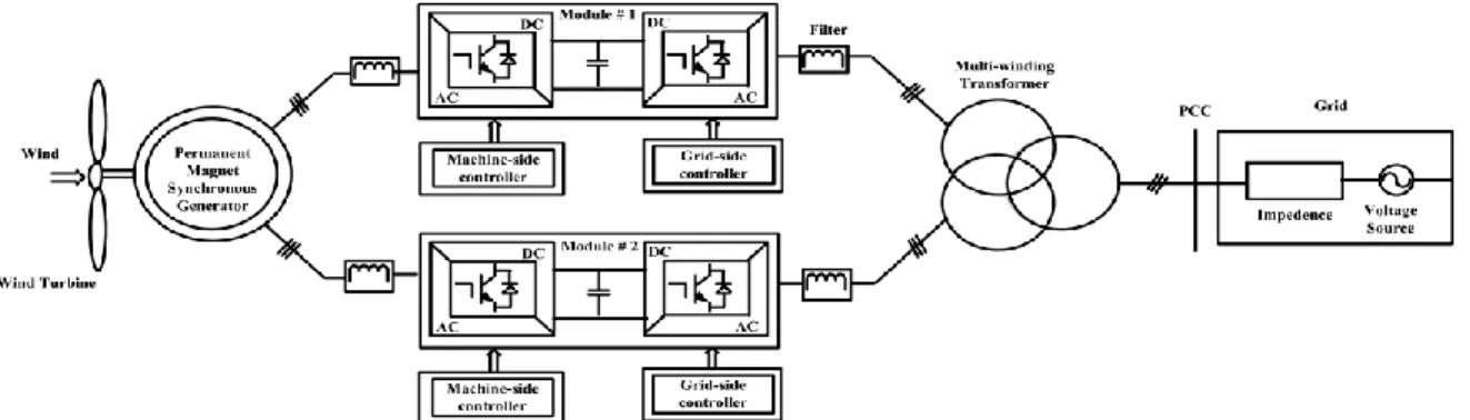
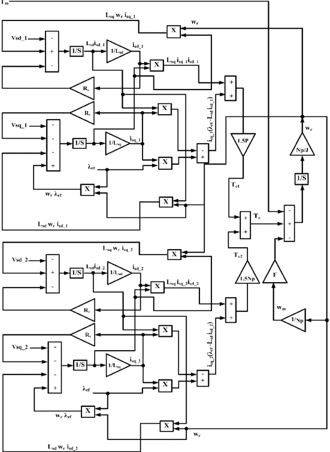
- Development of Simulink model for multi-phase PMSG
- Types of Synchronous Generator
- Reference frames for control
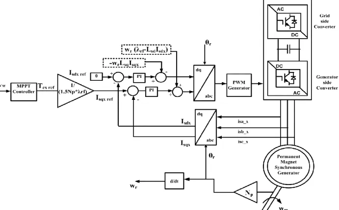
- Machine-side Controller
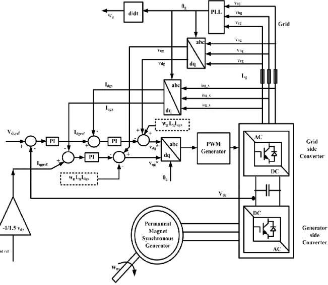
- Grid-side controller
- Simulation results
- Summary
The first part of the series is called the rotor reference frame (RRF), whose d-axis is aligned with the rotor flow. The last of the three choices is the stator flux reference frame (SFRF), which is oriented perpendicular to the SVRF [1]. These strategies are classified based on the reference framework used to implement them [30].
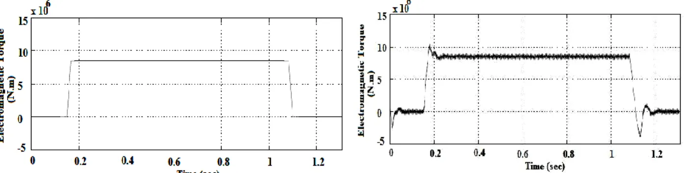
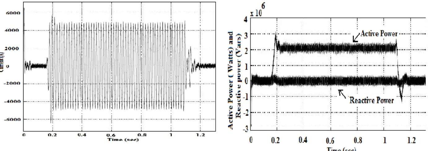
As mentioned in the generator side controller design, the q-axis stator current component is responsible for controlling the electromagnetic torque of the PMSG. The measured DC link voltage follows the reference value in each of the two channels as shown in the figure. The stator current flowing in phase A of one of the three-phase winding assemblies is shown in the figure.
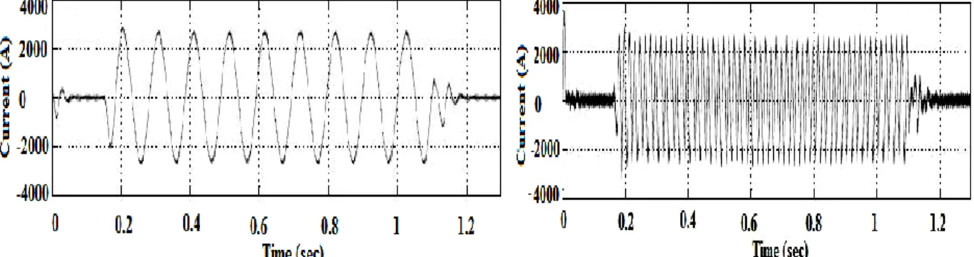
Similarly, the current flowing through phase A from one of the channels to the grid is given in Figure 2.

Development of interleaving control algorithm
- Introduction
- Main design challenges
- Different stages of algorithm development
- First stage
- Second stage
- Simulink model based on developed control algorithm
- Simulation results
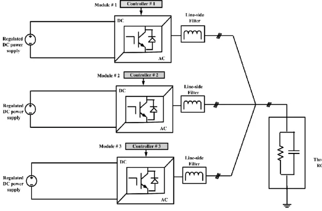
- System of parallel inverters feeding common RC load
- Results of WECS with interleaving controller
- Summary
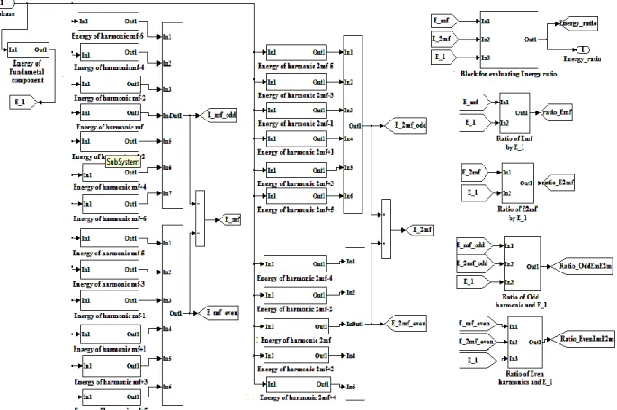
The name given to this term is Energy Ratio (EH) and its mathematical definition is given by This newly defined term will be referred to repeatedly in the upcoming section of this chapter and will serve as a criterion for estimating the best possible embedment angle for the system of parallel operating converters. A change in carrier phase shift resulting in a change in Energy Ratio (EH) of the measured load side phase current will verify the authenticity of the concept and will pave the way for the development of the final interleave control algorithm. Simulation of the same system is also performed for different settings of interleaving angle.
The observations made regarding the system of three parallel inverters are very important as they verify our idea that the energy ratio (EH) is affected by the choice of the carrier phase shift between the units of the modular converter system. Based on the information obtained from the previous section, it is now possible to proceed with the development phase of the control algorithm for the interfacing of the parallel operation inverter system. The partial answer to the first challenge in controller design was given in the last section, and the controllers connected to each of the inverter modules will determine the energy ratio of the total phase current to the load side.
Record the energy ratio (EH) of the total load side phase current for each case. The flow chart of the developed crosstalk control algorithm for a three-channel system is shown in Fig. The flow chart of the algorithm section responsible for token generation is shown in Fig.
The defined energy ratio (EH) is given as input to each controller that is connected to one of the parallel inverter units. The section of the model with a centralized structure which is responsible for generating the token and the reset signal is shown in Fig. 3.13. In Fig. 3.14 is shown the internal view of the subsystem that sets the value of the best angle of intersection.
For comparison, the minimum of the three energy values is selected by the block that appears in the right-hand corner of Fig 3.14. This concludes discussion of the portion of the Simulink model for automatic interleaving of modular converters. In the case of the other channel, DC link voltage shoots up from its reference level when converter #2 is turned off.
In the system development phase of the algorithm of parallel inverters feeding a common RC load was used.
Experimental verification
- Introduction
- Platform used for embedded controller
- Code generation for TI microcontroller .1 Introduction to VisSim
- Stages of embedded control design
- Experimental results
- Analysis of results
- Summary
From transducer data sheets given in appendix A-5, it is found that the number of secondary turns (Nsecondry) is fixed; however, by setting the appropriate number of turns of the primary current cable (Nprimary), the measuring range of the transducer can be easily adjusted. The voltage drop across measuring resistor (Rm) is the signal fed to the analog input port of the DSP board. In light of this limitation, it is important to ensure that the output of the transducer, when fed to the analog input port of the eZdsp, is appropriately scaled.
Scaling of the sensor output signal can be done using a voltage divider and a current buffer. It is important to note that this control algorithm relies heavily on FFT analysis of the feedback signal and implementing the same using a fixed-point DSP requires very efficient source code. This will allow the PWM block to run on the eZdspF2812 while the rest of the algorithm runs on the PC.
At the end of the linking process, a *.out file is generated that can be fully run on the DSP [38]. The sine signal that appears on the screen of one of the binoculars is the voltage drop (Vsecondry) across the measuring resistor Rm. The results of the FFT analysis for each carrier phase shift are in the form of a bar graph and are pasted in column 3 of Table 4.2.
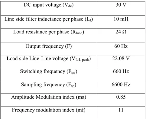
The maximum value of the fundamental harmonic component and the recorded % THD value are expressed at the top of each of the bar graphs. It is important to mention that the THD (discrete) block starts giving non-zero output only after completing one cycle of the input signal which translates to 1/60 sec. The simulations are performed for three different crossing angles 0º, 72º and 180º and the FFT analysis of the simulated waveform for the three cases is shown in column 2 of this table.
By comparing the three results, we find that even in this case, value of %THD calculated for load side phase current is the lowest, when the carriers of the two inverter modules are displaced by an angle of 180º. Consequently, unwanted harmonic components especially low-order harmonics appear in output causing an overall distortion of the VSI's voltage waveform [39].
Conclusions
- Conclusions
- Major contributions
- Future work
Appendix A-1
Appendix A-2
These blocks are highly optimized as they contain handwritten assembly routines developed specifically for Texas Instruments DSP. For this reason, the execution speed of these blocks when running on F2812 is much faster than an equivalent user created composite block [37].
Appendix A-3
Activ_Access_Board: During the testing of the developed control algorithm, it is necessary to switch ON or OFF the parallel operating inverter units. There is a row and column number associated with each of the push buttons and once pressed, information of its respective location is stored in a 16-bit register called RX_DATA (address: 203A). Comparing the contents of variable _FA1 to either of the two hex numbers quoted above will determine if either converter is disabled.
PWM_for_inverters: The composite block named PWM_for_inverters and its internal view are shown in the figure. Since TMSF2812 can generate six pairs of PWM output signals, it is therefore possible to use PWM1 to PWM6 for one of the inverters and PWM7 to PWM12 for the other inverter module. The main segments of the composite block shown in Figure A.3.6 are two F281X_Full Compare PWM blocks and each of these units has four inputs.
Three of these inputs control the duty cycle of PWM waveforms scaled to the 1IQ16 format. The fourth pin is an enable pin which, if at logic zero, would cause the PWM block to be deactivated. The presence of IGBTs in the inverter legs requires the use of a small time delay between the on/off times of the two switches sharing the same inverter leg.
This composite block consists of many important units which are also composite in nature. The input of these two blocks is the output of the block named FFT, details of the same will follow shortly. As its name suggests, the Modulating_ signal block is responsible for producing 60 Hz modulating sine waves for each of the three phases.
By comparing the outputs of the Modulating_ signal block with the output of Carrier_1, three signals (A1, A2, and A3) are generated that carry duty cycle information for the six switches of the full-bridge inverter module. The difference between the assignment values stored in variables A1 and Da_inv1 is the format of the variables, where A1 is in integer format while Da_inv1 is in scaled integer format 1IQ16.

Appendix A-4
Appendix A-5
12] Miller, S.K.T.; Beechner, T.; Jian Sun; , "Comprehensive Study of Harmonic Failure Effects in Interleaved Three-Phase VSCs," Power Electronics Professionals Conference, 2007 PESC 2007. Ooi, "Forced-commutated HVDC and SVC based on phase-shifted multiconverter modules," Power Delivery, IEEE Transactions on Power Delivery, IEEE Transactions on, vol.8, p. Rowan, “Current regulator instabilities on parallel voltage source converters,” IEEE Transactions on Industry Applications, vol.
21] Casablanca, C.; Jian Sun;, "Interleaving and Harmonic Cancellation Effects in Modular Three-Phase Voltage-Sourced Converters", Computers in Power Electronics, 2006. D., "Analysis of Electric Machinery and Drive Systems", 2nd Edition, IEEE Press, John Wiley and Sons, 2002. Haskew and Ling Xu, “Conventional and Novel Control Designs for Direct Drive PMSG Wind Turbines,” Electric Power Systems Research 80 (March pp.
Hartkopf, "Control strategy for a variable speed wind turbine with multipole permanent magnet synchronous generator", in: 2007 European Wind Energy Conference and Exhibition, Milan (IT), 7-10. May, 2007. 31] Keyuan Huang; Shoudao Huang; Feng she; Baimin Luo; Luoqiang Cai; "A Control Strategy for Direct-Drive Permanent-Magnet Wind Power Generator Using Back-to-Back PWM Converter," Electrical Machines and Systems, 2008.