The practical problems of aerodynamic shape design must balance the goal of optimizing performance over a range of design operating conditions with the need to meet design constraints under various off-design operating conditions. Such design problems can be presented as multipoint optimization problems where the on-design and off-design operating conditions are represented as design points with corresponding objective or constraint functions.
Overview of Aerodynamic Shape Optimization
An objective function is formulated to evaluate the performance of the mold with respect to the design objectives. As with multi-objective optimization, a composite objective function is formed as a weighted sum of the objective functions at each design point.
Review of Multipoint Optimization Applications
Multi-objective optimization has the benefit of allowing competing design objectives to be prioritized through weight assignments. Regarding multi-objective optimization problems, a designer may be interested in the trade-offs in performance associated with each of the design objectives.
Practical Aerodynamic Design Problems
Performance under on-design operating conditions is compromised by the need to satisfy off-design constraints. However, a practical aerodynamic design problem may include off-design points that will have their constraints satisfied regardless of the weight applied to them, called redundant points.
Objectives
The anomalous design weights mentioned above refer to the weights applied to the respective anomalous objective functions in the composite objective function. The off-design points in this method are not included in the composite objective function (which contains only on-design objectives).
Grid Perturbation
The optimization algorithm changes the vertical coordinates, Yic, of the B-spline control points to make local changes to the airfoil geometry.
Flow Solver
A coordinate transformation is used to map the curvilinear grid surrounding the airfoil in the physical domain to a grid in the computational domain with uniform spacing equal to one. The spatial derivatives of the Navier–Stokes equations are discretized using second-order centered differences, and the temporal derivative is neglected for steady flows, resulting in the nonlinear system of equations commonly referred to as the residual, given by .
Objective Functions
The linear system resulting from each Newton iteration is inexactly solved using the generalized minimum residual Krylov subspace (GMRES) method to obtain ∆Qb(n). In order to ensure the global convergence of Newton's method, an implicit Euler time scheme using the ARC2D approximate factorization approach in diagonal form [17] is used as an initial algorithm to obtain a good initial solution, Qb(0), for Equation 2.14.
Gradient Evaluation
Substituting ΨT into Equation 2.25 and rearranging it reveals the gradient of the objective function with respect to the design variables. Newton iterations are performed until a solution x∗ is found that satisfies equation 3.3, within a user-defined tolerance.
BFGS Algorithm for Unconstrained
Quadratic penalty method for geometric constraints
For the cases in this thesis where the BFGS algorithm is used within Optima2D, the thickness constraints are added as quadratic penalty terms to the objective function. The penalty conditions, Tj, are given by. 3.18) where h(xj) is the thickness of the airfoil at locationxj in the chord direction, and h∗(xj) is the target thickness.
SNOPT Algorithm for Constrained
The quadratic model of the Lagrangian at each QP subproblem uses an approximation of the Lagrangian's Hessian. SNOPT minor iterations are the steps required to minimize the quadratic model of the Lagrangian at each QP subproblem.
Design Problem Definition
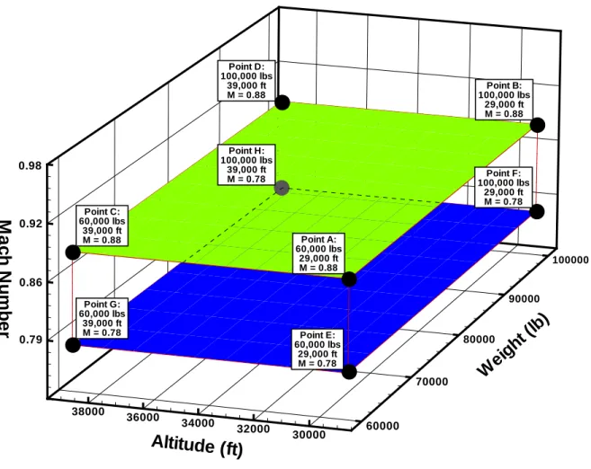
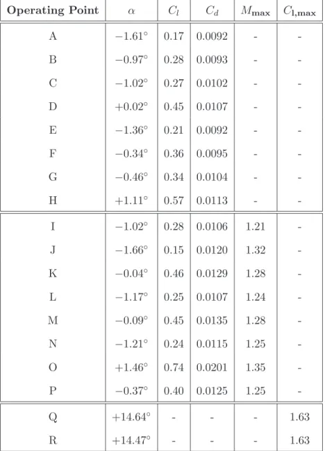
Cruise and long-range cruise conditions represented by design points A-H are considered design operating conditions. A complete problem specification may include a careful prioritization by the designer of these operating conditions based on knowledge of the aircraft's mission requirements. The next eight operating conditions (I-P) are accompanied by a safety requirement for maneuvering in submerged conditions.
For operating condition Q, the altitude is sea level, the weight is 60,000 lbs, and the effective Mach number is 0.16.

A Strategy For Obtaining Ideal Weights For Off-Design Points (Method 1) 27
Weight update formula
For non-design points with a maximum local Mach number constraint, Mmax≤Mmax∗, the values of ψn and ψ∗ to be used in the weight update formula are defined in Equations 4.7 and 4.8, respectively. The first application of the weight update formula to obtain initial off-design weights ω1 requires special treatment because there are no previous weights to use in the formula. The off-design constraint values ψ0 are evaluated using the original airfoil geometry (or the first airfoil geometry in the design in some cases).
The weight update formula is then used at regular intervals (after each weight update cycle) throughout the main optimization process to update the weights of the off-design points.
Angle of attack sweep to obtain C l,max
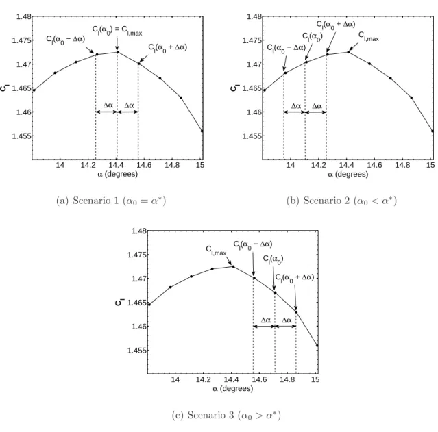
Solving Practical Aerodynamic Design Problems 32 An arbitrary value of unity is assigned to ω0 for all points outside the design. It is important to clarify that the ω0 weights are not used at any point during the optimization procedure; they only facilitate the calculation of ω1. In this case, a0 gives a good estimate of Cl,max; therefore set Cl,max = Cl(α0) and return to the calculation of the high lift limitation ψn.
In this case α0 is successively reduced by ∆α until Cl,max is bracketed as in scenario 1; then go back to the high lift limit calculation.
Weight update cycles
An Alternative Strategy Using Constrained Optimization (Method 2)
- On-design-first optimization with SNOPT
- KS function used for evaluation of maximum Mach number con-
- Evaluation of high-lift constraints
- Off-design constraint function gradients
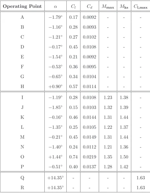
A maximum Mach number limitation function is used at off-design points I-P, and a high-light limitation function is used at off-design points Q and R. Off-design points I-P representing dive conditions are subject to the constraint that the maximum Mach number in the flow field does not exceed 1.35. Down design points Q-R representing design requirements for high lift at low speeds are subject to the constraint that Cl,max must be at least 1.60.
To take advantage of the existing adjoint gradient evaluation capabilities of Optima2D, described in Section 2.5, new definitions for the partial derivatives ∂J∂Qb and ∂J∂X have been created for the off-design constraint functions Mks and Cl.
Parallel Computing Implementation
Off-design weight update setup for Cases 1 - 3
For the design points Q and R, the design objective is to meet the minimum requirements for Cl,max at low speeds. Off-design objective functions at design points I - R are used to satisfy corresponding off-design constraints as described in Section 4.2. The objective functions at all design points are normalized by their respective objective function values obtained using the original airfoil geometry.
The weights for the off-design points I to R are periodically adjusted during the optimization procedure according to the strategy described in section 4.2.
Determination of parameter values for KS constraint function
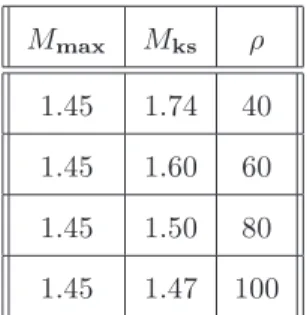
The weights for design points A - H remain fixed at unity throughout the duration of the optimization procedure. A trial and error approach was used to find the appropriate combination of Mks∗ and ρ to produce Mmax= 1.35 at all off-design points where the Mmax constraint is active in the final optimized solution. As ρ decreases, the difference between Mks and Mmax becomes larger, so the effect of decreasing the value of ρ to a constant value of Mks∗ results in a lower value of Mmax.
Conversely, for a fixed value of ρ, the difference between Mks and Mmax remains approximately constant, so the eMmax value moves in step with Mks∗.
Constrained optimization setup for Case 4
The target value Mks∗ is used by SNOPT as the upper bound on the constraint function. It appears that for this case there are lower limits onMks∗ andρbelow below which SNOPT cannot obtain a converged solution. These results show that the combination of Mks∗ = 1.50 and ρ= 31 is suitable to obtain Mmax= 1.35 at point O.
It should be noted that the adaptive KS approach proposed by Poon and Martins [16] can provide an alternative strategy to the trial-and-error method presented in this section, which removes the guesswork involved in the eliminate determination of Mks∗ and ρ.
Case 1 - Baseline 18 Point Optimization
Off-design points
Figures 5.4 and 5.5 show the evolution of the constraint values for unplanned I-P and Q-R points, respectively, throughout the entire optimization process. From Figure 5.6, it can be seen that the off-design constraint at point O is the most difficult to satisfy, as evidenced by its large weight compared to the other active points Q and R. The weight update strategy recognizes this feature of redundant off-design points and reduces their weights accordingly to zero as shown in Figure 5.6.
Throughout the optimization procedure, the off-design constraint value at point Q,Cl,max is slightly higher than the Cl,max constraint value at point R, as shown in Figure 5.5.
On-design points
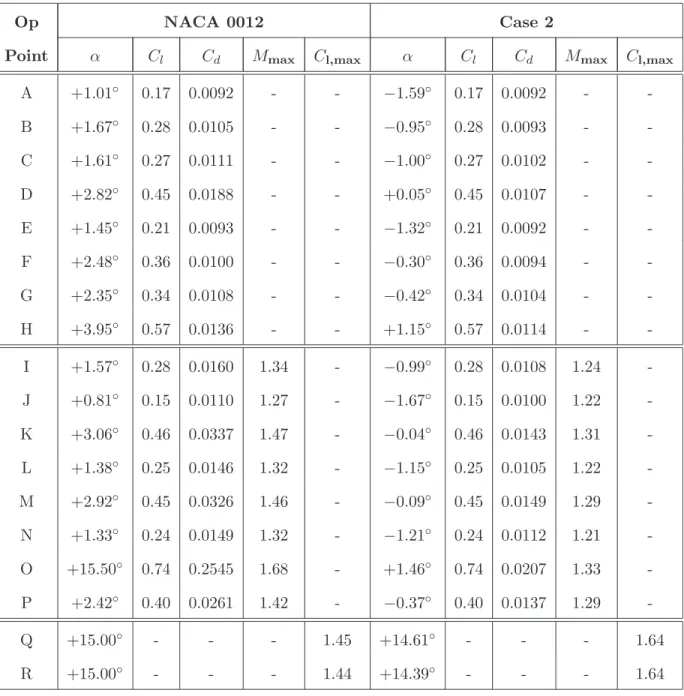
Case 2 - Alternate Initial Airfoil
The weight for the non-design point O is significantly different in both cases, while the weights on the points Q-R are similar. If there are enough weight update cycles, the anomalous weight for point O for case 2 can be closer to the value obtained in case 1, although for both cases some difference in the final point O weight should be expected due to the fixed leading edges. The significant improvement in the performance of the final optimized airfoil compared to the baseline performance of the NACA 0012 airfoil indicates that the NACA 0012 airfoil is poorly suited to this specific design problem.
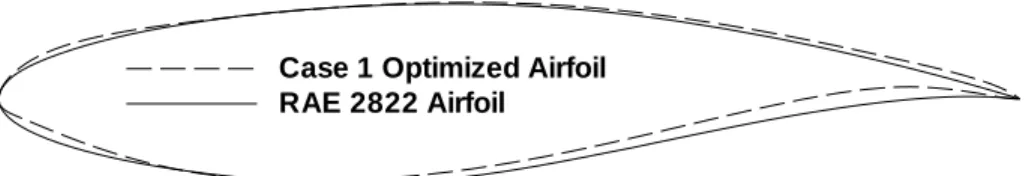
In contrast, the RAE 2822 airfoil used in Case 1 is a more appropriate first guess as a solution to this design problem in terms of initial design performance and off-design constraint violation.

Case 3 - Reduced Set of Off-Design Points
These results show that the final wing geometry and performance values for case 3 are very similar to the results obtained for case 2. Both cases required a similar number of design iterations and weight update cycles, but only 10 flow solutions and additional calculations were performed per design iteration. required for this case compared to 18 for case 2. A logical extension of this work would be to investigate methods to predict redundancy of anomalous design points, although an experienced designer may be able to do this successfully.
Case 4 - Full Set of Off-Design Points Using SNOPT
Furthermore, this technique is able to prevent over-satisfaction of off-design constraints in order to minimize their negative impact on design performance. The main features of the off-design weight update method summarized above are described in detail in Case 1. An additional optimization run using the weight update procedure with a reduced set of off-design points confirms that the same pavement can be obtained optimized. with sig-.
The second method using the constrained optimization algorithm SNOPT is able to produce the same results as the undesigned weight update method, but with significantly less computational effort as shown in Case 4.
Future Work
- Representative sampling of flow field Mach numbers to reduce KS
- Adaptive KS approach
- Design under uncertainty
- Linearize pressure switch used in artificial dissipation calculation . 65
- Effect of the number of design variables on optimization
- Effect of mesh density on optimization
- Pareto front generation
- Extension of methods to three-dimensional optimization problems 68
A disadvantage of the SNOPT method is the trial and error process required to obtain the appropriate values of the parameters ρ and Mks associated with the KS function necessary to achieve compliance with the Mmax constraints. Solving a practical aerodynamic design problem using the SNOPT method may require 3 or 4 trials using different combinations of ρ and Mks to achieve satisfaction of the Mmax constraints. The source of this inaccuracy can be attributed to the pressure switch used in the calculation of the second-order artificial dissipation term.
Given that the computational cost of aerodynamic profile optimization increases with the increase in the number of design variables, it would be reasonable to investigate the effect of the number of design variables on the optimization results.
Case 2
Case 3
Case 4