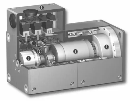
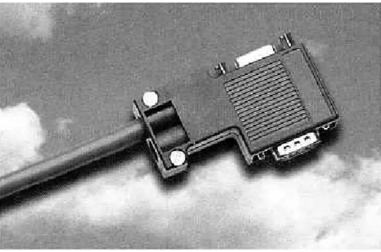
The control and power electronics are fully integrated on the connection block inside the modules. I would like to thank him for his invaluable supervision, full support and critical review of the manuscript.
Literature Survey
The remote control unit has some specific buttons according to certain built-in functions of the robot. A lot of research has been done on Internet-based remote control, which establishes a connection between the robot and the user via the Internet.
Subject of Study
It greatly reduces network traffic and makes real-time monitoring, web browsing, and remote management much faster and more stable without disconnection, latency, and downtime. Although this task works on a single robotic arm, this arm contains all the necessary functions.
The Organization of the Thesis
Among them, D-H representation is an important milestone in robot kinematics. the i-link, where link 0 is the base and link n is the end effector. The absolute value of b is the distance between X and X. The angle between Z and Z is defined as α and is measured about the positive direction of X.
General Design of the SRMR System
The Objective of SRMR System
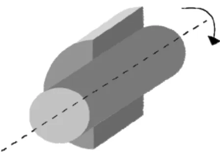
A revolute joint (also called a pin joint or hinge joint) is a one-degree-of-freedom kinematic couple used in mechanisms. In this thesis, the serial four-degree-of-freedom manipulator is constructed from all rotating joints.
Requirements Analysis
- Requirements at Server Side
- Requirements at Client Side
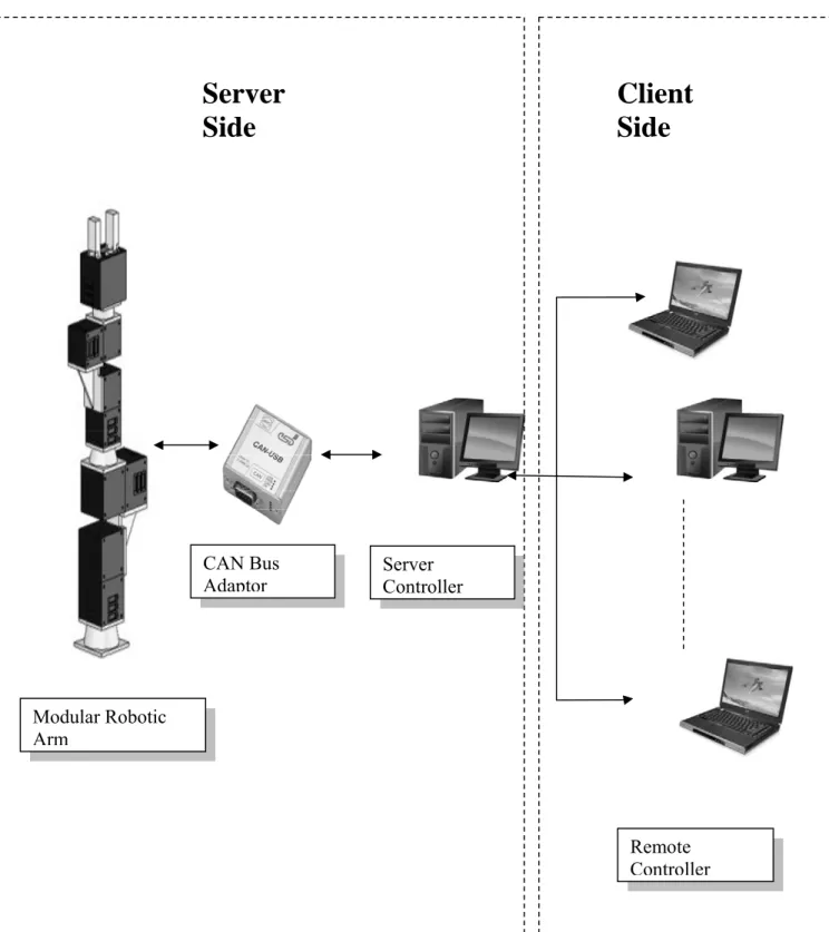
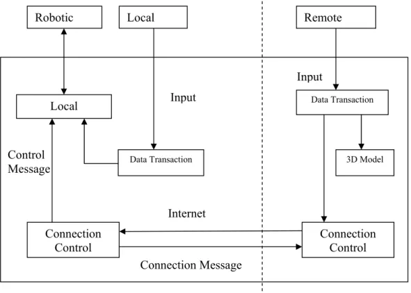
The server controller will be able to connect to the modular robot arm via CAN bus. The client side should be able to simulate the motion for robot arm independently, without connecting to the server.
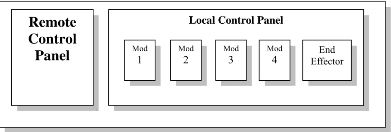
Proposed SRMR System Design
In addition to the robot arms, this system also includes power supply system, CAN bus, terminal block and computer controller. The other computers can act as clients and remotely control the robotic arms through a socket.
Summary
27] Jianhe Lei, “Application of Neural Network to Nonlinear Static Decoupling of Robot Wrist Force Sensor”, The 6th World Congress on Intelligent Control and Automation, 2006. 28] Jorge Angeles, “Fundamentals of Robotic Mechanical Systems Xiangrong Xu, Xiaogang Wang and Feng Qin , “Trajectory Planning of Robot Manipulators by Using Spline Function Approach”, The Third World Congress on Intelligent Control and Automation, 2000.
Hardware Architecture of SRMR System
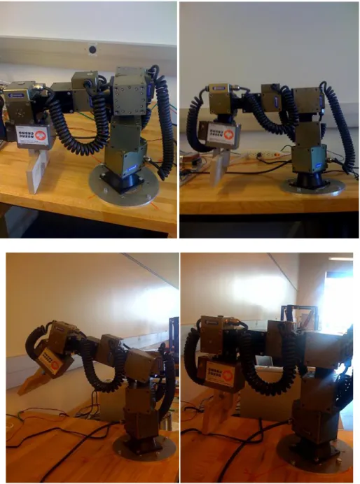
Modular Robotic Arm Assembling
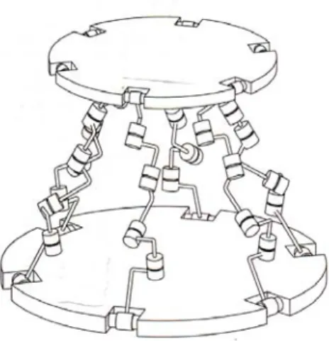
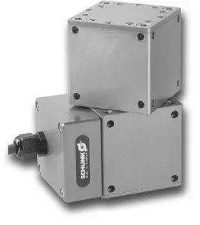
There are six different modules in PowerCube series: PG for servo-electric 2-finger Parallel Gripper, PR for servo-electric Rotary Actuators, PW for servo-electric Rotary Pan Tilt Actuators, PSM for servo motors with. Each PowerCube module is connected using the connection block (Fig. 3.4), which is located above the control electronics.
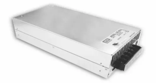
Power System Design
Standard features include: built-in remote sensor function, built-in DC fan, output voltage adjustment, short-circuit protection, overload protection, over-temperature protection and over-voltage protection.
Control Area Network Bus and Protocol
- Types of Field Bus
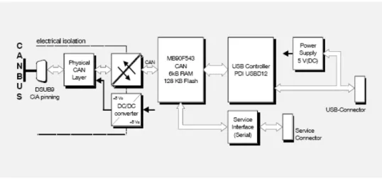
- Hardware of CAN Bus Module
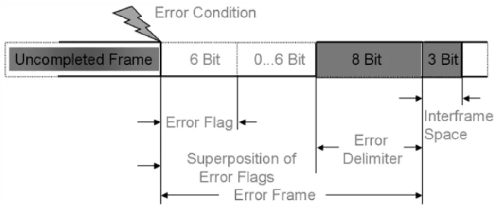
- CAN Data Transmit and Frame Protocol
The CAN USB Mini Module is an intelligent CAN interface with an MB90F543 microcontroller for local CAN data management. This allows it to evaluate the data from the CAN controller, which can be retrieved from the connected sensor system and actuators.
Debugging the Hardware of SRMR System
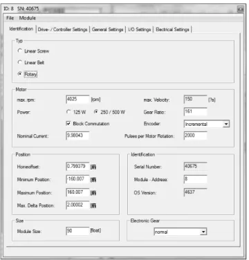
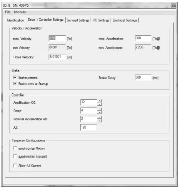
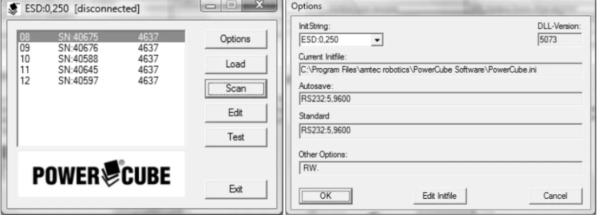
In the module dialog there are five property sheets to configure and customize the modules. According to the initial setting, CAN bus is set with baud rate 250 for the module. Zero Moves after HOK can automatically move the module to its zero position after homing.
On page “Electrical settings” (Fig. 3.22), the user can configure the electrical parameter of the module. After all the module robot configurations are set up, users can test them with specified movements. All state data of the module can be accessed from the "Module Test" page (Fig. 3.23) and the PowerCube modules can be moved in position, velocity, current and loop mode.
Summary
Private Sub Button11_Click(ByVal sender As System.Object, ByVal e As System.EventArgs) Handles Button11.Click. Private Sub Button12_Click(ByVal sender As System.Object, ByVal e As System.EventArgs) Handles Button12.Click. Private Sub Button14_Click(ByVal sender As System.Object, ByVal e As System.EventArgs) Handles Button14.Click.
Private Sub Button15_Click(ByVal sender As System.Object, ByVal e As System.EventArgs) Obravnava Button15.Click. Private Sub Button18_Click(ByVal sender As System.Object, ByVal e As System.EventArgs) Obravnava Button18.Click. Private Sub Button19_Click(ByVal sender As System.Object, ByVal e As System.EventArgs) Obravnava Button19.Click.
Software of SRMR System Design
Development of Server Control Platform
- Server Programming Language
- Server Control Panel GUI Design
The structure of the Basic programming language is very simple, especially regarding the executable code. VB.net is not only a language, but also an integrated, interactive development environment ("IDE"). The graphical user interface of VB.net-IDE provides intuitively attractive views for managing the program structure in the large and different types of entities (classes, modules, procedures, forms...).
VB.net is a component integration language that conforms to Microsoft's Component Object Model ("COM"). It issues a quick stop of the module specified by the device ID and module ID to avoid a dangerous situation. By calling a read operation (canRead() or canTake()) one or more CAN messages are copied from the FIFO handle into the application's address space.
Development of Client Control Platform
- Client Programming Language
- Java3D Model
- Client Control Panel GUI Design
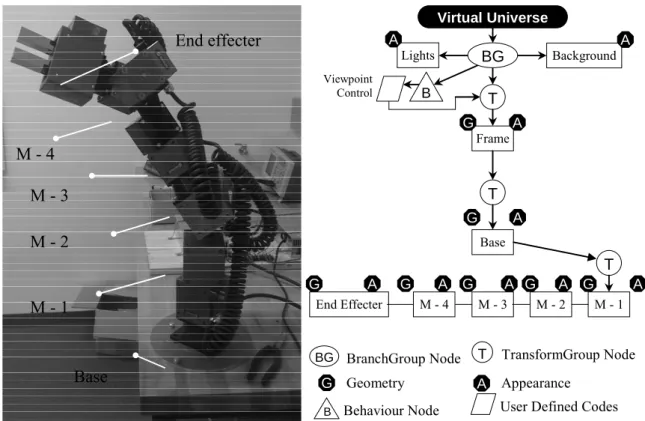
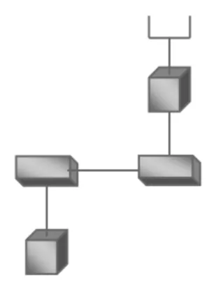
Programs written in Java 3D can be run on various types of computers and over the Internet. With calculated position and scale, the 3D model of the robot arm can be created as shown in Figure 2. In the motion class, the first x, y and z coordinates are determined in a global system and used to set the location of each module set.
In the constructor, the rotation directions, speed, angles and loop times can be specified for each module. The second module can also rotate around the Y axis with the first module and meanwhile the second module can also rotate around its own X axis as shown in figure. In the meantime, the results are sent to the server side to control the real robot arm.
Development of Communication via Internet
- Communication at Server
- Communication at Client
A socket address combines an IP address (the location of the computer) and a port (the type of a communication service) into a single identity. The following server-side code opens the server's address and selects a port for the client to connect to. However, the data is not immediately usable as all data is sent in string type, so the following code is created to convert data types.
As soon as the server gets data from the client, it will convert the data to the double type required for this program. The following code creates a stream socket and connects it to the specified port number on the specified IP address. Optionally, a PrintStream can be created so that it is flushed automatically; this means that the flush method is automatically called after a byte array is written, one of the println methods is called, or a newline character or byte ('\n') is written.
Summary
Private Sub Button1_Click (ByVal sender As System.Object, ByVal e As System.EventArgs) Handles Button1.Click. Private Sub Button5_Click (ByVal sender As System.Object, ByVal e As System.EventArgs) Handles Button5.Click. Private Sub Button9_Click (ByVal sender As System.Object, ByVal e As System.EventArgs) Handles Button9.Click.
Private Sub Button22_Click(ByVal sender As System.Object, ByVal e As System.EventArgs) Obravnava Button22.Click. Private Sub Button23_Click(ByVal sender As System.Object, ByVal e As System.EventArgs) Obravnava Button23.Click. Private Sub Button26_Click(ByVal sender As System.Object, ByVal e As System.EventArgs) Obravnava Button26.Click.
Case Study
Modular Robot Kinematics
- Geometric Structure
- Forward Kinematics Analysis
- Inverse Kinematics Analysis base on VA Method
- Inverse Kinematics Analysis base on ANN Method
According to the configuration of the actual robot arm, the geometric structure in Fig. In its frame, Z is the axis of the i-pair and represents the direction of the joint axis. To find the DH table, the geometric model of robot arm can be analyzed as Fig.
The position vector P of the operating point of the end effector can be calculated as follows:. cosθ sinθ cosθ cosθ sinθ sinθ L cosθ sinθ sinθ sinθ cosθ cosθ sinθ L cosθ L cosθ L L sinθ cosθ cosθ L cosθ sinθ L. 5.1.3 Inverse kinematic analysis based on the VA method. Therefore, the vector algebraic method [25] is used in the diploma thesis, which is without the disadvantages of the matrix method. We choose different combinations of joint angles and substitute them into the forward kinematics to obtain the coordinates of the end effector.
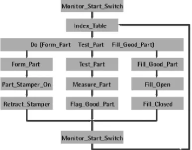
Motion Trajectory Planning
Once the coefficients of each polynomial are determined, the motion of all nodes can be marked. Based on the above path trajectory method, a pick and place test is done, shown in Fig.
Summary
Private Sub Button3_Click(ByVal sender As System.Object, ByVal e As System.EventArgs) Hanteer Button3.Click. Private Sub Button4_Click(ByVal sender As System.Object, ByVal e As System.EventArgs) Hanteer Button4.Click. Private Sub Button8_Click(ByVal sender As System.Object, ByVal e As System.EventArgs) Hanteer Button8.Click.
Private Sub Button16_Click(Dërguesi ByVal As System.Object, ByVal e As System.EventArgs) Handles Button16.Click. Private Sub Button25_Click(Dërguesi ByVal As System.Object, ByVal e As System.EventArgs) Handles Button25.Click. Private Sub Button28_Click(Dërguesi ByVal As System.Object, ByVal e As System.EventArgs) Handles Button28.Click.
Conclusion and Future Work
Contributions of the Thesis
Private Sub Button2_Click(ByVal sender As System.Object, ByVal e As System.EventArgs) Handles Button2.Click. Private Sub Button6_Click(ByVal sender As System.Object, ByVal e As System.EventArgs) Handles Button6.Click. Private Sub Button7_Click(ByVal sender As System.Object, ByVal e As System.EventArgs) Handles Button7.Click.
Private Sub Button10_Click(Dërguesi ByVal As System.Object, ByVal e As System.EventArgs) Handles Button10.Click. Private Sub Button13_Click(Dërguesi ByVal As System.Object, ByVal e As System.EventArgs) Handles Button13.Click. Private Sub Button17_Click(Dërguesi ByVal As System.Object, ByVal e As System.EventArgs) Handles Button17.Click.
Private Sub Button20_Click (ByVal sender As System.Object, ByVal e As System.EventArgs) Handles Button20.Click. Private Sub Button21_Click (ByVal sender As System.Object, ByVal e As System.EventArgs) Handles Button21.Click.
Conclusion
Future Work