38
fixed-bed reactor and the concomitant difficulty in handling fine particles. The use of carbon powders processed into pellets (cylindrically-shaped pieces) [17] or monoliths [18], on the other hand, it can reduce the ratio of catalyst mass to reactor volume, as well as the pressure drop in the bed. In addition, formation of hotspots could be prevented. Thence, a pelletized or monolith-based catalytic system would greatly facilitate scaling-up the reactions. However, although monolithic structured AC-based catalysts or adsorbents have been widely used for abatement of pollutant emissions [19-21], there are no reports in the literature on the use of AC-based pelletized catalyst. The pelletizing process consists of mixing activated carbon with a binder (which helps to keep the carbon particles in a compressed state), followed by the addition of an adequate amount of water to form a paste that is subsequently shaped by compression-molding; the final step is the pyrolysis treatment to favor graphitization and removal of excess binder in the resulting material [22].
1. Introduction
As a result of their very-large surface area and strong adsorption capacity, Activated Carbons, AC, are widely used in air and water purification, energy storage, carbon dioxide fixation, and as supports for the preparation of powdered catalysts [1]. In particular, Table 1 [2-16] lists some of the reactions that have been studied with catalysts supported on AC. However, these processes were performed with powdered catalysts. Therefore, despite their good performance scaling-up of these processes is not yet feasible because of the large amount of catalyst that would be required, as well as the significant pressure drop in a
Pelletization of catalysts supported on activated
carbon. A Case Study: clean synthesis of
dimethyl carbonate from methanol and CO
2
ABSTRACT:
The synthesis of Cu-Ni bimetallic catalyst supported on pellets of activatedcarbon using carboxymethylcellulose (CMC) as a binder is reported. The effect of preparation conditions, such as binder concentration, AC/binder ratio, temperature, and pyrolysis heating rate on the surface area of the pellets, was evaluated. Cu and Ni metals were incorporated on the pellets by conventional incipient wetness impregnation. The support and the synthesized catalysts were characterized using N2 adsorption, H2-TPR, XRD and SEM-EDS techniques. The pelletized catalysts were evaluated for the direct synthesis of dimethyl carbonate DMC (case study). An improved catalytic activity (e.g., ca. 20% increase in conversion) in structured pelletized catalyst in comparison to the powdered catalyst was found.
RESUMEN:
Se presenta la síntesis del catalizador bimetálico de Cu-Ni soportado enpellets de carbón activado utilizando carboximetilcelulosa (CMC) como agente aglutinante. Se evaluó el efecto de las condiciones de preparación, tales como concentración de CMC, relación de CMC/Carbón activado, temperatura y velocidad de calentamiento en la pirólisis sobre el área la superficial de los pellets sintetizados. La incorporación de los metales (Cu y Ni) en los pellets se efectuó por impregnación húmeda incipiente convencional. El soporte y los catalizadores sintetizados se caracterizaron mediante adsorción de N2, H2-TPR, XRD y técnicas de SEM-EDS. Los catalizadores peletizados se evaluaron en la síntesis directa de dimetil carbonato DMC (caso de estudio), mostrando una actividad catalítica mejorada en comparación con el catalizador en polvo.
* Corresponding author: Felipe Bustamante Londoño e-mail: felipe.bustamante@udea.edu.co
ISSN 0120-6230 e-ISSN 2422-2844
ARTICLE INFO
KEYWORDS
Dimethyl carbonate, pellets, activated carbon, CO2, Cu-Ni catalysts
Dimetil carbonato, pellets, carbón activado, CO2, catalizador Cu-Ni Received May 18, 2015 Accepted October 28, 2015
Revista Facultad de Ingeniería, Universidad de Antioquia, No. 78, pp. 38-47, 2016
DOI: 10.17533/udea.redin.n78a05
Preparación de catalizadores de carbón activado estructurados. Un caso de estudio: síntesis limpia de
dimetil carbonato a partir de metanol y CO
2Andrés Felipe Orrego-Romero, Oscar Felipe Arbeláez-Pérez, Felipe Bustamante-Londoño*, Aída Luz Villa Holguín
39
Although it is expected that binder-catalyst interactions should have no significant influence on the activity, selectivity and stability of the catalyst, depending on the binder and/or preparation conditions, there may be a detrimental effect on some textural and morphologic properties of the catalyst, such as surface area, porosity or pore-size distribution. Both organic and inorganic materials have been used as binders in the pelletization of the activated carbon, but organic binders such as phenolyc resin, cellulose powder, polyvinyl alcohol [23], polyvinyl acetate [24], ethyl cellulose and carboxi methyl cellulose (CMC) [25], have attracted more attention because of their good binding properties, inertness and similar chemical nature (relative to activated carbon) which facilitates processing the pellets. In order to have strong, resistant, water- and thermally-stable pellets when CMC is used as binder, the preparation conditions, such as binder loading, temperature and heating ramp during pyrolysis, must be carefully selected in order to minimize pore blocking of the activated carbon and maintain properties such as surface area, microporosity or pore-size distribution. The purpose of this work was, therefore, to understand the effect of experimental conditions in the pelletizing process of commercial activated carbon powder with CMC as binder and obtain optimal preparation conditions to yield pellets with mechanical resistance and minimal impact on catalytic activity. In order to accomplish this, the best experimental conditions for preparing pellets were used for synthesizing Cu, Ni and Cu-Ni catalysts, which were evaluated in the clean, direct synthesis of dimethyl carbonate (DMC) from
CO2 and methanol in gas-phase (see reaction (1)).
2 CH
3OH + CO
2(CH
3O)
2CO + H
2O
(1)
DMC is an important chemical product used as a methylating agent, intermediate in the production of higher carbonates and oxygenated fuel additive, and the direct synthesis provides an environmentally-friendly alternative to established processes such as the phosgenation of methanol. Furthermore, the direct synthesis of DMC has been reported on different catalysts supported on Activated
Carbon, such as Cu/AC (CH3OH conversion 2.16%) [26],
Ni/AC (CH3OH conversion 1.43%) [26], Cu-Ni/AC (CH3OH
conversion 6.6%) [10]. Even though higher conversions were reported with other catalysts, namely Ce-Zr oxide/
graphene (CH3OH conversion 58%) [27], as CeO2 cannot be
easily pelletized [28] we chose Cu-Ni/AC for our case study. The experimental results of the pelletized catalyst were compared with the conventional powder Cu-Ni bimetallic catalyst.
2. Experimental
2.1. Preparation of activated carbon
pellets and Cu-Ni/AC pellets
Commercial activated charcoal (AC), Merck (90% particle size < 125 μm), was mixed with an ethanolic solution of carboxymethylcellulose (CMC) as binder; different concentrations of the binder were used, namely 10 wt. %, 20 wt. %, and excess of CMC. The solution was stirred and heated softly for 24 h until ethanol evaporation. The remaining solid was wetted with enough water to form a paste, which was pressed in a uniaxial hydraulic system at 1 metric ton for 15 minutes. The compacted carbon was then extruded in cylindrical shape and cut in pellets (ID 3.175 mm x 4 mm). After drying at 80 ºC for 12 h, the pellets were pyrolyzed for
1 hour at 375, 500 or 700 ºC in flowing N2 (25 mL/min) using
several heating ramps (1, 5, 10 or 20 ºC /min). The effect of CMC concentration in the ethanolic solution (wt. %), pyrolysis temperature, heating ramp, and AC/binder ratio
(g AC/(cm3 ethanolic binder solution)) on surface area of
resulting pellets was evaluated. Additionally, two resistance tests were performed for the pellets obtained with each AC/ binder ratio; the tests consisted in determining the weight loss of the pellets after treatment in an ultrasonic bath (test 1) or rotation procedure (test 2). Pellets were submerged in water in test 1, and in both ammonia solution and water in test 2; details are given below.
[image:2.612.107.516.83.236.2]Bimetallic Cu-Ni/AC catalysts were prepared by conventional wetness impregnation of pellets obtained under the optimal preparation conditions. The preparation conditions used in this work are based on previously reported work
40
[13]. Cu(NO3)2·3H2O (Carlo Erba, 99.5%) and Ni(NO3)2·6H2O
(Merck, 99%) were used as metal precursors, and the Cu:Ni molar ratio was fixed at 2:1 with a nominal metal oxide (CuO + NiO) loading of 15 wt. %. The Cu:Ni molar ratio and metal loading were selected to yield a Cu-Ni alloy phase according [13, 26]; furthermore, this molar ratio translates into a significant synergistic effect with respect to the monometallic catalysts [10, 26]. After addition of the precursor solution to AC pellets the resulting mixture was rotavapored at 25 rpm and 180 mmHg of vacuum for 3 h, and then the impregnated pellets were dried at 90 ºC for
12 h and pyrolyzed by heating in flowing N2 (25 mL/min) at
0.5 ºC/min up to 500 ºC; this temperature was held for 2 h.
Finally, the solid was heated in flowing 5% H2/Ar at a rate of
0.5 ºC /min to 600 º C, and held at this temperature for 3 h. The catalyst was labeled as Cu-Ni (2:1)/AC. Monometallic samples of Cu and Ni supported also on carbon pellets, labeled as Cu/AC and Ni/AC, respectively, were prepared for comparison purposes. All pellet and catalyst samples were stored in desiccators under inert atmosphere before using them.
2.2. Catalyst characterization
Specific surface areas of powder and pellets of carbon were
determined by N2 adsorption at 77 K in a Micromeritics
Autochem II 2920 equipped with a TCD detector, using the single-point method. Samples were pretreated in flowing
30% N2/He (25 mL/min) at 250 ºC for 30 minutes (using a
heating ramp of 10 ºC/min). Nitrogen adsorption/desorption isotherms (77 K) of the final catalysts were determined using a Micromeritics 2375 BET instrument equipped with a Vacprep 061 degasser. Prior to measurements, samples were degassed for 2 h at 250°C and 0.15 mbar to ensure a clean and dry surface. The Brunauer-Emmett-Teller (BET) and the Barrett-Joyner-Halenda (BHJ) approaches were used to determine the surface area and pore-size
distribution, respectively. H2-TPR experiments of oxidized
catalyst samples were performed in a Micromeritics AutoChem II 2920 apparatus. In order to ensure a free oxygen atmosphere, 50 mg of samples were pretreated at 5°C/min to 250 °C for 1 h in flowing helium (70 mL/min), and then cooled down to 40 °C. Thereafter, samples were
heated to 800 °C using 5% H2/Ar (70 mL/min) at 8°C/min.
Signals of H2 consumption were continuously monitored by
a thermal conductivity detector (TCD). The crystallinity of synthesized materials was determined by X-ray diffraction (XRD) on a Phillips PW 1740 diffractometer using Cu Kα radiation and Ni filter operated at 40 kV and 20 mA at room temperature. The scanning range was 5° ≤ 2θ ≤ 70° at 2°/min. The diffractograms were compared to JCPDS (Joint Committee of Powder Diffraction Standards) data. The crystallite size of mono and bimetallic particles was calculated from the broadening of X-ray diffraction pattern using the Scherrer’s Eq. (2)
B hkl
K
D
cos
2
(2)
Where Dhkl is the average crystallite size (nm), β2θ is the
broadening of the full width at half maximum (FWHM) of
the main peak (radians), θB is the Bragg’s angle (degrees),
K is the Scherrer’s constant (a value of K=0.94 for spherical crystals with cubic symmetry [29] was assumed in this work), and λ is the radiation wavelength (nm). This formula is applicable to crystal structures with particle size smaller than 100 nm [30].
SEM images were taken with a JEOL JSM-6490 microscope using an accelerating voltage of 20kV. Elemental analysis was performed by an energy dispersive X-ray spectroscopy (EDS) instrument coupled to the SEM equipment.
Chemical composition (i.e., Cu and Ni content) of the monometallic and bimetallic samples were determined by atomic absorption spectroscopy (AAS) on a Philips PU9200, using Rhodium radiation at 40 kV. Prior to the analysis the sample (0.05 g) was digested in a 3:1 hydrochloric acid - nitric acid solution.
2.3. Catalytic tests
Catalytic tests were performed in a continuous stainless steel (SS) tubular fixed-bed reactor (ID 7 mm) packed with 1.7 g of catalyst. After catalyst loading, the reactor was sealed and purged using Ar. Methanol vapor was
introduced into the reactor by a stream of CO2 flowing
through a SS bubbler containing the liquid alcohol at room temperature. Reaction temperature was controlled by a hot-box system that included an electric forced-convection heater to keep both the reactor and the bypass at the same temperature, avoiding possible condensation in the process lines. The proportional pressure control used a pressure sensor with an accuracy of ±0.1 bar. All experiments were
carried out at PCO2 of 10 bar, GHSV of 988 h-1 and varying
temperature between 70 and 130ºC; in particular, GHSV was selected according to values reported in the literature for the gas-phase reaction with powdered catalysts [31, 32]. Reactants and products were analyzed online by a mass spectrometer QMS Thermostar 200 (Pfeiffer) and the by-products were determined by gas chromatography (GC– Varian Star 3400, equipped with FID detector and a capillary column DB-WAX (length 60 m ID 0.25 mm)).
Catalytic activity of the pellets was determined by methanol conversion and DMC selectivity, Eqs. (3) and (4), respectively.
100 ]
OH CH [
] OH CH [ ] OH CH [ (%) Conversion Methanol
3 3
3
in out in
(3)
100
]
products
by
[
]
DMC
[
]
DMC
[
(%)
y
Selectivit
DMC
(4)
3. Results and discussion
3.1. Effect of preparation conditions
on pellet
’
s surface area
41
applications as adsorbent, namely the change in surface area of the pellets with respect to the powder, was used in this work as criterion to determine the best preparation conditions. Figure 1 compares the surface area of activated carbon with several binder loadings (prior to pyrolysis) with that of commercial carbon powder without binder. A drastic decrease in the surface area of commercial carbon by adding 10% CMC binder is observed. Besides, surface area decreased by almost the same proportion when the binder loading increased from 10 to 20%. A further increase in CMC concentration, on the other hand, appears to have a much lower impact on surface area.
AC powder 10%CMC 20%CMC Excess CMC 0
200 400 600 800 1000 1200 1400
S
A
(m
2 /g
[image:4.612.73.291.203.377.2])
Figure 1
Effect of binder loading on the surface
area (SA) of carbon samples before pyrolysis
The net effect of the CMC concentration on the carbon surface area may be further evidenced once the samples are pyrolyzed. Figure 2 shows the surface area of samples in pellets and powder (particle size lower that 125 μm); commercial carbon without binder and pyrolyzed at the same temperature is also shown as comparison.
375 500 700 375 500 700
200 400 600 800 1000 1200
Temperature (375 500 700C)
Powders <125 m
S
A
(m
2 /g
)
Pyrolysis Temperature (C)
Commercial AC 10% CMC 20% CMC Excess CMC
Pellets 600
700 800 900 1000
SA
(
m
2 /g
) Pellets Powders <125 m 10%CMC Results
0 2 4 6 8 10
Figure 2
Effect of pyrolysis temperature on the
surface area (SA) of carbon pellets and powders
(<125 μm) treated with different CMC loadings.
The insert compares the effect on SA for both
pellets and powders treated with 10% CMC
A decrease in surface area with respect to the commercial carbon without binder was observed for carbon powder with different CMC loadings. At each pyrolysis temperature a reduction in surface area occurs with increasing of CMC loading. The effect of decreasing area occurs for the three pyrolysis temperatures tested where a strong trend of surface area reduction with increasing CMC loading is evidenced. A similar effect is observed with carbon pellets but the surface area values are lower than for powders. On the other hand, TGA-DTG studies [33] revealed that thermal degradation of the CMC occurs between 325 and 350°C. As our pyrolysis temperatures are higher, it is expected a complete decomposition of CMC. Failure to fully recover the initial surface area of the activated carbon, however, may indicate presence of binder residues after pyrolysis treatment, which may block the pores of the carbon, decreasing the surface area even at high pyrolysis temperature. The decrease on surface area is less significant when a binder concentration of 10% in both powder and pellets is used. This is more clearly shown by the insert in Figure 2, which compares the surface area of powders and pellets prepared with 10% CMC loading; whereas the surface area remains almost constant with carbon powders, surface area of the pellets increases with temperature and becomes comparable to powders at 700°C. According to these results, a pyrolysis temperature of 700 °C is considered as an appropriate temperature for treating carbon pellets. Finally, the increase in surface area with pyrolysis temperature observed in some cases may be the result of changes in pore size and pore distribution that would occur at higher temperature of pyrolysis, which, in turn, can affect the surface area of carbon.
The effect of heating rate on the surface area of the pellets
was evaluated with a ratio of 15 g AC/200 cm3 ethanolic
solution (10 wt.% CMC) and at a pyrolysis temperature of 700 °C, Figure 3. Surface area of all pyrolyzed samples was larger than the surface area of the non-pyrolyzed pellet. In fact, in the non-pyrolyzed pellets the binder would be deposited inside the pores of the carbon, resulting in lower surface area, and, upon pyrolysis the binder is decomposed favoring graphitization and removal of binder from the pores [22]. The percent of deviation from the non-pyrolyzed surface area for the sample heated at 20°C/min was similar to that of the sample heated at 5°C/min. While the pyrolysis temperature is a key factor in the preparation of pellets, the heating rate also plays an important role. In fact, the heat of desorption of the gases produced from the
decomposition of CMC (mainly H2, CO2, CO, CH4, C2H6, C2H4
[33]) should be considered [34, 35], because this complex process involves different types of interactions with the
activated carbon (e.g., between -CH2COO- groups and the
surface of carbon layers). Consequently, it can be expected that the higher heating ramp (20°C/min) may favor the decomposition process and, as a result, translate into an increased surface area compared to the ramp of 5°C/min. Therefore, in order to reduce the time of exposure of the carbon to high temperatures, a ramp of 20°C/min was fixed for the pyrolysis treatment.
Once the heating ramp was set, the effect of the amount of binder added to the carbon powders on surface area was evaluated. Specifically, surface areas of pyrolyzed pellets obtained with mixing ratios of 15/200, 25/200 and 50/200
[image:4.612.68.290.499.667.2]42
in surface area is more significant as the ratio AC/CMC(sln)
increases. In fact, surface area increases from 453 m2 /g to
900 m2 /g when the AC/CMC(sln) ratio changes from 15/200
to 50/200. On the other hand, an increase in surface area with respect to non-pyrolyzed pellets was higher with the sample prepared with a ratio of 15/200, whereas the other two samples showed a similar increase with respect to their non-pyrolyzed counterparts.
1 5 10
20-300 350 400 450 500 550
Heating Rate (°C/min)
+27%
+14% +25%
S
A
(m
2 /g
)
+43%
357 m2/g
[image:5.612.76.298.163.336.2]NON PYROLYZED
Figure 3
Effect of heating rate of pyrolysis at 700
°C on the surface area of the pellets. Percent
on bars indicates the difference on surface area
with respect to pellet non-pyrolyzed (357 m
2/g)
15/200 25/200 50/200
300 400 500 600 700 800 900 1000
+6.5%
+6.6%
S
A
(m
2 /g
)
g AC/ mL CMC(sln) Non pyrolyzed
Pyrolyzed at 700°C
+27%
Figure 4
Effect of carbon/binder ratio on the
surface area of the pellets. Percent on bars
indicates the difference on surface area with
respect to non-pyrolyzed pellet
Regarding the surface area of the final material, Figure
4 suggests using the highest AC/CMC(sln) ratio. However,
a loss in consistency was observed when handling such sample; thus, resistance tests on pyrolyzed pellets were performed in order to assess the degree of compaction achieved for each mixture ratio used. These tests consist in determining the weight loss of the pellets after being subjected to vibration in an ultrasonic bath for 90 minutes (test 1) and rotation at 100 rpm and 60 °C for 3 hours in a rotavapor (test 2), Table 2. While a 50/200 mixing ratio favors the surface area of carbon pellets (Figure 4), the results of test 1 show that the consistency of these samples is severely affected, as indicated by the weight loss of 42.3 %, compared to weight losses of 22.5% and 11.8% for the 25/200 and 15/200 ratios, respectively. Results of test 2 show that weight loss with water for 25/200 and 15/200 ratios in the rotation test are almost equal, whilst weight loss with the 50/200 is larger (7.8%). From these results,
an AC/CMC(sln) ratio of 25/200 appears to be an adequate
mixing ratio for preparing pellets as suggested by the good degree of compaction and improved mechanical resistance after both vibration and rotation tests. Moreover, the
treatment of pellets in H2O results in a lower weight loss
than that observed when the treatment was conducted in an ammonium hydroxide solution.
The comparison between solvents is important since the impregnation of metals over carbon has been conventionally conducted with aqueous ammonia solutions of the salt precursors [36]; our results, on the other hand, indicate the convenience of using water instead of ammonium hydroxide as the dispersion medium of the salt precursors, since it translates into carbon pellets with higher surface area. The AC/binder ratio and the heating rate for the pyrolysis treatment that ensure carbon cylinders that retain its shape without being damaged by handling were established and used to prepare pellets impregnated with Cu and Ni metals.
In summary, the preferred conditions to prepare pellets from activated carbon powders with high surface area using CMC as a binder are: solution of 10% CMC in, carbon-binder
ratio of 25 g AC/200 mL CMC(sln), and pyrolysis at 700 °C with
a heating ramp of 20°C/min.
3.2. Catalyst characterization
[image:5.612.100.514.654.730.2]Catalyst characterization for the bimetallic Cu-Ni (2:1)/AC sample was compared against the monometallic samples. Table 3 summarizes surface areas and metal composition
Table 2
Weight loss of pyrolyzed pellets after vibration in an ultrasonic bath for 90 min (test 1) and
43
of fresh catalyst samples. It is observed that metal loading affects the surface area of carbon (surface area is
764 m2 /g prior to impregnation). The AC surface area was
[image:6.612.74.300.195.249.2]reduced between 10 and 19% after impregnation, pyrolysis and activation with hydrogen. The decrease in surface area may be associated with remnants of binder in the catalyst and/or sintering due to the high temperatures of pyrolysis and reduction steps at 500°C and 600°C, respectively.
Table 3
BET surface area and metal loadings of
[image:6.612.314.548.272.345.2]fresh catalyst samples
Figure 5 shows X-ray diffraction patterns of mono and bimetallic copper-nickel catalysts. XRD for AC support (not shown) exhibited a broad and low intensity peak at 2θ = 23°, associated with activated carbon [11].
30 35 40 45 50 55 60 65 70
Cu-Ni(2:1)/AC
Ni/AC
Int
e
ns
it
y (
a
.u.
)
2degree
Cu/AC Cu0, JCPDS 4-0836
[image:6.612.69.293.351.515.2]Ni0, JCPDS 4-0850 Cu-Ni alloy, JCPDS 47-1406
Figure 5
XRD of mono and bimetallic catalyst
samples
Monometallic samples Cu/AC and Ni/AC display peaks
corresponding to Cu0 (2θ = 43.3˚, 50.4˚, JCPDS file No.
4-0836 [37]) and Ni0 (2θ = 44.5˚, 51.8˚, JCPDS file No. 4-0850
[38]), respectively, indicating the formation of crystalline metal particles. Characteristic and well-defined diffraction peaks related to cubic phase Cu-Ni solid solution (2θ = 43.7˚, 50.9˚, JCPDS file No-47-1406) [39] for Cu:Ni molar ratio of 2:1 were observed in the bimetallic catalyst, indicating that Ni and Cu atoms were well mixed at atomic level [40], i.e., alloyed. Finally, the XDR patterns indicate the presence of metallic Cu, Ni and a cubic phase Cu-Ni alloy that were probably formed during reduction treatment. The crystallite sizes of copper, nickel and Cu-Ni alloy particles present in mono and bimetallic samples calculated with the Scherrer’s equation are shown in Table 4. The estimated values for
FWHM and θB were obtained from fitting the diffraction
pattern at (111) plane with a Lorentzian function [30]. It is
observed that the crystallite size of bimetallic sample (23.9 nm) is closer to the size of Cu (23.5 nm) than to Ni (17.3 nm). On the other hand, particle size distribution was obtained from TEM of the powdered catalysts (not shown). Although the results may be different from the observed in the pellets, the comparison with crystallite size obtained by XRD of the pellets may be illustrative. In fact, although the average crystallite size of the bimetallic catalyst observed by TEM of the powdered catalysts (14.3 nm) is smaller than the value obtained from XRD of the pellets (23.9 nm), both techniques indicate that the crystallite size of the bimetallic catalysts is larger than the crystallite size of the Ni catalysts (10.8 and 17.3 nm from TEM and XRD, respectively). Therefore, the Cu would act as a “host” for Ni in the Cu-Ni solid solution.
Indeed, a moderate antisegregation (i.e., Ni tends to stay in the bulk) has been reported for Cu-Ni alloys [41].
Table 4
Crystallite size of selected samples Cu,
Ni and Cu-Ni/AC
Nitrogen adsorption/desorption isotherms for monometallic and Cu-Ni (2:1) catalysts, Figure 6, showed no significant changes with respect to AC support, indicating that catalysts retain the characteristic morphology of the support. Besides, the bimetallic catalyst displays a better adsorption capacity in agreement with its higher surface area compared to monometallic catalysts. All samples exhibited type IV isotherms with hysteresis loop type H4 according to IUPAC classification. These isotherms are usually found on mesoporous solids consisting of aggregated particles or agglomerates forming slit-shaped pores, with non-uniform size and shape [42]. The BHJ pore diameter distribution shows that all samples had narrow pore size distribution between 3 and 3.6 nm.
0.0 0.2 0.4 0.6 0.8 1.0
100 150 200 250 300 350 400 450
1 10
0.00 0.03 0.06 0.09 0.12
Ni Cu Cu-Ni
AC
Cu-Ni (2:1)/AC
Ni/AC AC
V
ol
. A
d
sor
b
e
d
(
c
m
³/
g S
T
P)
P/P
0
Cu/AC
d
V/
d
D
(cm
3 /g
-n
m
)
[image:6.612.320.544.519.723.2]Pore Diameter, (nm)
Figure 6
N
2adsorption/desorption isotherms
44
TPR profile of fresh Cu monometallic catalyst, Figure
7, displays a main reduction peak at 251°C and a weak shoulder at 290°C attributed to a two-step reduction of CuO
to Cu2O and Cu0 [43], respectively. TPR of Ni monometallic
catalyst sample shows a main reduction peak at 281°C, and a smaller one at 380°C, both ascribed to reduction of NiO to
Ni0 [44]. The shoulder at 242°C is attributed to the reduction
of well–dispersed NiO particles on AC support [17]. An additional peak at 306°C, not found for the monometallic samples, was observed for the Cu-Ni(2:1)/AC sample. This points to the formation of Cu-Ni alloy species [45]. The broad peak observed after 500 °C, with a maximum at 600 °C, is associated with the partial gasification of carbon
support due to CH4 formation from the reaction of C and H2
[46]; in fact, this peak is also present in the AC, indicating that the metals do not affect the high-temperature behavior of the support.
0 100 200 300 400 500 600 700 800 900
AC
Cu/AC Ni/AC
TC
D s
igna
l (
a.
u)
Temperature (C
Cu-Ni/AC (2:1)
Figure 7
TPR profiles for activated carbon pellets
AC, monometallic Cu/AC and Ni/AC and bimetallic
Cu-Ni/AC 2:1 samples
Table 5 presents the consumption of H2 in the TPR; the
theoretical consumption was calculated from the actual
metal loading (see Table 3) assuming a ratio of 1 mol H2 per
mol of metal oxide (i.e., CuO or NiO). Interestingly, despite its much lower amount in the catalysts (2.7 wt.% of Ni and 8.7 wt.% of Cu, see Table 3) the presence of Ni translates into an improved reducibility of the bimetallic catalyst.
Some typical SEM images are shown in Figure 8. From Figure 8(a) and Figure 8(b), it was possible to confirm the effective diameter of the pellets, 3.07 and 3.21 mm, respectively, values that are very close to the nominal size (3.175 mm). Figure 8(c) and Figure 8(d) confirm the presence of metal particles after the impregnation of activated carbon pellets. Specifically, energy dispersive X-ray analysis (not shown) suggests that white circular dots observed in Figure 8(d) correspond to clusters of metal particles of Cu and Ni with a surface chemical composition of 12.14% and 4.29%, respectively.
3.3. Catalytic activity
Effect of reaction temperature
Figure 9 shows the effect of reaction temperature on methanol conversion for pellets and powders under
constant pressure (10 bar) and GHSV (988 h-1); DMC
selectivity of the pellets is also shown. An increase in the conversion of methanol is evidenced when catalyst is used in form of pellets instead of powder. This increase could be associated with the reduction in pressure drop in the reactor, which is close to 20% when powders are used in the bed.
(a) (b)
[image:7.612.314.547.208.622.2]
(c) (d)
Figure 8
SEM images of (a) Ni/AC pellet; (b)
Cu-Ni/AC 2:1 pellet; (c) AC x5000; (d) Cu-Ni/AC
2:1x5000
70 80 90 100 110 120 130 0
2 4 6 8 10 12
Temperature (°C)
M
et
ha
nol
C
onve
rs
ion (
%
)
40 45 50 55 60 65 70 75 80
P
elle
ts
S
ele
ctiv
ity
(
%
)
Figure 9
Effect of reaction temperature on
methanol conversion (solid symbols) and DMC
selectivity (open symbols) for pellets and
powders. Catalyst weight: 1.7 g; P
CO2= 10 bar;
GHSV 988 h
-1 [image:7.612.69.293.263.437.2]45
to 130°C; this trend would suggest a decrease of CO2
adsorbed on the catalyst at high temperature. These trends are in agreement with those reported by [26], who showed an optimum temperature at 105°C using powdered bimetallic Cu-Ni/AC catalyst. Furthermore, previous studies of the gas-phase reaction over several materials [47-50] have been performed at temperatures from 40°C to 280°C, with optimum temperatures between 80°C and
130 °C. The simultaneous activation of methanol and CO2
in this range of temperature would favor the formation of dimethyl carbonate over other products that would result from individual activation of the reactants. At lower temperatures, methanol conversions remain low, and at 110°C the selectivity towards DMC is drastically affected due of the tendency for methanol to form other reaction products such as HCHO, CO, methyl formiate, dimethyl ether, dimethoxy methane, as well as the decomposition of DMC which increases over acidic catalysts [51].
Stability test
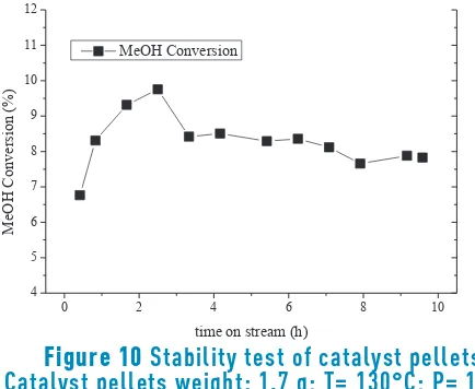
The catalytic performance was evaluated in terms of methanol conversion during 10 hours of reaction. The test
was carried out at 130°C, 10 bar and a GHSV of 988 h-1;
the results are shown in Figure 10. Methanol conversion increases up to 2.5 h of reaction, and then slowly declines to a steady-state value at around 8%. The results obtained in this work are similar to powdered catalysts evaluated at 130°C and 10 bar which exhibited stable activity during 10 hours of reaction [26]; these conditions were selected to avoid partial condensation during the (long) test, according to a vapor-liquid equilibrium study previously reported [52]. Therefore, the pelletized catalyst is a promising material for DMC industrialization or application for new scale-up methodologies.
0 2 4 6 8 10
4 5 6 7 8 9 10 11 12
M
eO
H
C
onve
rs
ion (
%
)
[image:8.612.76.537.82.151.2]time on stream (h) MeOH Conversion
Figure 10
Stability test of catalyst pellets.
Catalyst pellets weight: 1.7 g; T= 130°C; P= 10
bar, GHSV 988 h
-14. Conclusions
In this work, the effect of the addition of binder to activated carbon powders to form pellets that could be used as structured catalyst supports was analyzed. It was found that mixing activated carbon powders with CMC binder in 10% ethanol solution, using a carbon-binder ratio of 25 g
AC/200 mL CMC(sln) and treating the mixture by pyrolysis at
700 °C with a heating ramp of 20 °C/min, results in a low loss of surface area of obtained pellets; moreover, the loss of surface area is almost comparable to pyrolyzed powders indicating that during pyrolysis stage the CMC content is removed from the surface and pores of the carbon. Pellets obtained under these preparation conditions also showed good consistency, being more resistant to weight loss when they are subjected to vibration and rotation tests. Successful wet impregnation of Cu and Ni metals on pellets was developed using water as solvent for metal precursors. Catalysts characterization showed that formed pellets of Cu-Ni(2:1)/AC had higher surface area than monometallic samples (Cu/AC and Ni/AC), as well as the co-existence of Cu-Ni alloy species and metallic sites of Cu and Ni. In addition, the metal particles were well dispersed on the surface of carbon. Furthermore, bimetallic Cu-Ni catalyst supported on AC retains its activity when pelletized under favorable conditions which yield higher surface of samples. Moreover, pellets shown stability for 10 hours of reaction. All previous studies in the Cu-Ni bimetallic catalysts have been conducted in powder form; therefore, as a breakthrough in the application of the direct synthesis at a larger scale, the catalyst was successfully pelletized.
5. Acknowledgments
The financial support from Universidad de Antioquia through CODI Project Grant E01557 is gratefully acknowledged
6. References
1. N. Díez et al., “A novel approach for the production of chemically activated carbon fibers”, Chem. Eng. J., vol. 260, pp. 463-468, 2015.
2. E. Gallegos, A. Guerrero, I. Rodriguez and A. Arcoya, “Comparative study of the hydrogenolysis of glycerol over Ru-based catalysts supported on activated carbon, graphite, carbon nanotubes and KL-zeolite”, Chem. Eng. J., vol. 262, pp. 326-333, 2015.
3. L. Pastor, R. Buitrago and A. Sepúlveda, “CeO2
[image:8.612.76.293.543.721.2]-promoted Ni/activated carbon catalysts for the water– gas shift (WGS) reaction”, Int. J. Hydrogen Energy, vol.
46
39, no. 31, pp. 17589-17599, 2014.
4. J. Zhao et al., “Enhancement of Au/AC acetylene hydrochlorination catalyst activity and stability via nitrogen-modified activated carbon support”, Chem. Eng. J., vol. 262, pp. 1152-1160, 2015.
5. D. Gudarzi, W. Ratchananusorn, I. Turunen, M. Heinonen and T. Salmi, “Promotional effects of Au in Pd–Au bimetallic catalysts supported on activated
carbon cloth (ACC) for direct synthesis of H2O2 from H2
and O2”, Catal. Today., vol. 248, pp. 1-11, 2014.
6. G. Zhang, A. Su, Y. Du, J. Qu and Y. Xu, “Catalytic performance of activated carbon supported cobalt
catalyst for CO2 reforming of CH4”, J. Colloid Interface
Sci., vol. 433, pp. 149-155, 2014.
7. L. Xu et al., “Catalytic CH4 reforming with CO2 over
activated carbon based catalysts”, Appl. Catal. A Gen., vol. 469, pp. 387-397, 2014.
8. T. Bao et al., “Supported CcoO4-CceO2 catalysts on
modified activated carbon for CO preferential oxidation
in H2-rich gases”, Appl. Catal. B Environ., vol. 119, pp.
62-73, 2012.
9. J. Bian et al., “Direct synthesis of dimethyl carbonate over activated carbon supported Cu-based catalysts”, Chem. Eng. J., vol. 165, pp. 686-692, 2010.
10. J. Bian et al., “Highly effective synthesis of dimethyl carbonate from methanol and carbon dioxide using a novel copper–nickel/graphite bimetallic nanocomposite catalyst”, Chem. Eng. J., vol. 147, no. 2-3, pp. 287-296, 2009.
11. J. Bian, M. Xiao, S. Wang, Y. Lu and Y. Meng, “Direct
synthesis of DMC from CH3OH and CO2 over V-doped
Cu–Ni/AC catalysts”, Catal. Commun., vol. 10, pp. 1142-1145, 2009.
12. H. Xie, et al.,“Investigating the performance of CoxOy/ activated carbon catalysts for ethyl acetate catalytic combustion”, Appl. Surf. Sci., vol. 326, pp. 119-123, 2015. 13. O. Arbeláez, A. Orrego, F. Bustamante and A. Villa,
“Direct Synthesis of Diethyl Carbonate from CO2 and
CH3CH2OH Over Cu–Ni/AC Catalyst”, Top. Catal., vol. 55,
no. 7, pp. 668-672, 2012.
14. P. Lazaridis et al., “D-Glucose hydrogenation/ hydrogenolysis reactions on noble metal (Ru, Pt)/ activated carbon supported catalysts”, Catal. Today, vol. 257, pp. 281-290, 2015.
15. A. Al-Hassani, H. Abbas and W. Wan Daud, “Hydrogen production via decomposition of methane over activated carbons as catalysts: Full factorial design”, Int. J. Hydrogen Energy, vol. 39, no. 13, pp. 7004-7014, 2014.
16. E. Liakakou, E. Heracleous, K. Triantafyllidis and A. Lemonidou, “K-promoted NiMo catalysts supported on activated carbon for the hydrogenation reaction of CO to higher alcohols: Effect of support and active metal”, Appl. Catal. B Environ., vol. 165, pp. 296-305, 2015. 17. E. Mostafavi, N. Mahinpey and V. Manovic, “A novel
development of mixed catalyst–sorbent pellets for
steam gasification of coal chars with in situ CO2
capture”, Catal. Today, vol. 237, pp. 111-117, 2014. 18. A. Podgornik, A. Savnik, J. Jančar and N. Krajnc,
“Design of monoliths through their mechanical properties”, J. Chromatogr. A., vol. 1333, pp. 9-17, 2014. 19. Y. Matatov and M. Sheintuch, “Catalytic fibers and
cloths”, Appl. Catal. A Gen., vol. 231, no. 1-2, pp. 1-16, 2002.
20. C. Moreno and A. Pérez, “Carbon-Based Honeycomb Monoliths for Environmental Gas-Phase Applications”, Materials, vol. 3, pp. 1203-1227, 2010.
21. F. Rezaei and P. Webley, “Structured adsorbents in gas separation processes”, Sep. Purif. Technol., vol. 70, no. 3, pp. 243-256, 2010.
22. D Lozano, D Cazorla, A Linares and D. Quinn, “Activated carbon monoliths for methane storage: influence of binder”, Carbon, vol. 40, pp. 2817-2825, 2002.
23. K. Smith, G. Fowler, S. Pullket and N. Graham, “The production of attrition resistant, sewage–sludge derived, granular activated carbon”, Sep. Purif. Technol., vol. 98, pp. 240-248, 2012.
24. A. Dashevsky, K. Kolter and R. Bodmeier, “Compression of pellets coated with various aqueous polymer dispersions”, Int. J. Pharm., vol. 279, pp. 19-26, 2004. 25. F. Yu, L. Luo and G. Grevillot, “Adsorption Isotherms of
VOCs onto an Activated Carbon Monolith: Experimental Measurement and Correlation with Different Models”, J. Chem. Eng. Data, vol. 47, no. 3, pp. 467-473, 2002. 26. J. Bian, M. Xiao, S. Wang, Y. Lu and Y. Meng, “Highly
effective direct synthesis of DMC from CH3OH and CO2
using novel Cu–Ni/C bimetallic composite catalysts”, Chinese Chem. Lett., vol. 20, pp. 352-355, 2009. 27. R. Saada, S. Kellici, T. Heil, D. Morgan and B. Saha,
“Greener Synthesis of Dimethyl Carbonate using a Novel Ceria-Zirconia Oxide/Graphene Nanocomposite
Catalyst”, Appl. Catal. B Environ., vol. 168, pp.
353-362, 2014.
28. J. Wang, W. Zhu, S. Yang, W. Wang and Y. Zhou, “Catalytic wet air oxidation of phenol with pelletized ruthenium catalysts”, Appl. Catal. B Environ., vol. 78, pp. 30-37, 2008.
29. G. Leofanti et al., “Catalyst characterization: characterization techniques”, Catal. Today, vol. 34, pp. 307-327, 1997.
30. A. Mikrajuddin and K. Khairurrijal, “Derivation of Scherrer Relation Using an Approach in Basic Physics Course”, J. Nanosains, vol. 1, pp. 28-32, 2008.
31. C. Li and S. Zhong, “Study on application of membrane
reactor in direct synthesis DMC from CO2 and CH3OH
over Cu–KF/MgSiO catalyst”, Cat. Today, vol. 82, pp. 83-90, 2003.
32. K. Almusaitee, “Synthesis of dimethyl carbonate (DMC)
from methanol and CO2 over Rh-supported catalysts”,
Catal. Comm., vol. 10, pp. 1127-1131, 2009.
33. D. de Britto and O. Assis, “Thermal degradation of carboxymethylcellulose in different salty forms”, Thermochimica Acta, vol. 494, pp. 115-122, 2009.
34. P. Webb and C. Orr, Analytical methods in fine particle
technology, 1st ed. Norcross, USA: Micromeritics
Instrument Corporation, 1997.
35. F. Delannay, Characterization of Heterogeneous
Catalysts, 1st ed. New York, USA: Marcel Dekker,
Inc., 1984.
36. J. Bian, M. Xiao, S. Wang, Y. Lu and Y. Meng, “Highly
effective direct synthesis of DMC from CH3OH and CO2
using novel Cu–Ni/C bimetallic nanocomposite catalysts”, Chin. Chem. Lett., vol. 20, no. 3, pp. 352-355, 2009.
47
deactivation under start–stop operating conditions”, J. Catal., vol. 247, pp. 112-118, 2007.
46. X. Zhang, Y. Zhang, Q. Liu and W. Zhou, “Surface properties of activated carbon from different raw materials”, Int. J. Min. Sci. Technol., vol. 22, pp. 483-486, 2012.
47. J. Bian, M. Xiao, S. Wang, Y. Lu and Y. Meng, “Carbon nanotubes supported Cu–Ni bimetallic catalysts and their properties for the direct synthesis of dimethyl carbonate from methanol and carbon dioxide”, Appl. Surf. Sci., vol. 255, no. 16, pp. 7188-7196, 2009.
48. X. Wu, M. Xiao, Y. Meng and Y. Lu, “Direct synthesis of
dimethyl carbonate on H3PO4 modified V2O5”, J. Mol.
Catal. A Chem., vol. 238, pp. 158-162, 2005.
49. A. Aouissi, A. Apblett, Z. AL-Othman and A. Al-Amro, “Direct synthesis of dimethyl carbonate from methanol and carbon dioxide using heteropolyoxometalates: the effects of cation and addenda atoms”, Transit. Met. Chem., vol. 35, pp. 927-931, 2010.
50. X. Wu, Y. Meng, M. Xiao and Y. Lu, “Direct synthesis of dimethyl carbonate (DMC) using Cu-Ni/VSO as
catalyst”, J. Mol. Catal. A Chem., vol. 249, pp.
93-97, 2006.
51. J. Zawadzki, B. Azambre, O. Heintz, A. Krztoń and J. Weber, “IR study of the adsorption and decomposition of methanol on carbon surfaces and carbon-supported catalysts”, Carbon, vol. 38, no. 4, pp. 509-515, 2000. 52. F. Bustamante, A. Orrego, S. Villegas and A. Villa,
“Modeling of Chemical Equilibrium and Gas Phase Behavior for the Direct Synthesis of Dimethyl Carbonate
from CO2 and Methanol”, Industrial & Engineering
Chemistry Research, vol. 51, pp. 8945-8956, 2012. copper particles by electrolytic synthesis and
characterizations”, Int. J. Physical Sci., vol. 6, pp. 3662-3671, 2011.
38. J. Ashok and S. Kawi, “Steam reforming of toluene as a
biomass tar model compound over CeO2 promoted Ni/
CaO–Al2O3 catalytic systems”, Int. J. Hydrogen Energy,
vol. 38, no. 32, pp. 13938-13949, 2013.
39. I. Baskaran, T. Sankara and A. Stephen, “Pulsed electrodeposition of nanocrystalline Cu–Ni alloy films and evaluation of their characteristic properties”, Mater. Lett., vol. 60, no. 16, pp. 1990-1995, 2006.
40. C. Jung, H. Lee, C. Kim and S. Bhaduri, “Synthesis of Cu – Ni alloy powder directly from metal salts solution”, J. Nanopart. Res., vol. 5, pp. 383-388, 2003.
41. B. Hammer and J. Nørskov, “Theoretical Surface Science and Catalysis—Calculations and Concepts”, Advances in Catalysis, vol. 45, pp. 71-129, 2000.
42. G. Leofanti, M. Padovan, G. Tozzola and B. Venturelli, “Surface area and pore texture of catalysts”, Catal. Today, vol. 41, pp. 207-219, 1998.
43. C. Chen, J. Lin, T. Lai and B. Li, “Active sites on Cu/SiO2
prepared using the atomic layer epitaxy technique for a low-temperature water–gas shift reaction”, J. Catal., vol. 263, pp. 155-166, 2009.
44. M. Cangiano, M. Ojeda, A. Carreras, J. González and M. Ruiz, “A study of the composition and microstructure of nanodispersed Cu–Ni alloys obtained by different routes from copper and nickel oxides”, Mater. Charact., vol. 61, pp. 1135-1146, 2010.
45. O. Ilinich, W. Ruettinger, X. Liu and R. Farrauto, “Cu–
Al2O3–CuAl2O4 water–gas shift catalyst for hydrogen