Visual SLAM algorithms for aerial robots
124
0
0
Texto completo
(2)
(3) ESCUELA POLITÉCNICA SUPERIOR. MASTER UNIVERSITARIO EN INGENIERÍA DE TELECOMUNICACIÓN TRABAJO DE FIN DE MÁSTER. VISUAL SLAM ALGORITHMS FOR AERIAL ROBOTS. Sergio García Gonzalo 2016.
(4)
(5) UNIVERSIDAD DE ALCALÁ Escuela Politécnica Superior MÁSTER EN INGENIERÍA DE TELECOMUNICACIÓN. Trabajo Fin de Máster. VISUAL SLAM ALGORITHMS FOR AERIAL ROBOTS Autor: Sergio García Gonzalo Tutora: María Elena López Guillén TRIBUNAL: Presidente: Manuel Rosa Zurera Vocal 1º: Miguel Ángel García Garrido Vocal 2º: María Elena López Guillén. FECHA: Junio 2016.
(6)
(7) Agradecimientos. “All we have to decide is what to do with the time that is given us.” ― J.R.R. Tolkien.. Ante todo quiero agradecer a mi familia su incondicional apoyo y paciencia, las cuales me han permitido llegar a ser lo que soy y poder estar escribiendo estas líneas. Gracias a mi padre, a mi madre y a mi hermano por todo. Quisiera expresar mi agradecimiento a todo aquel que me haya ayudado a llegar hasta aquí. Considero que sin la guía, experiencia y afán de mi tutora, la Dra. Elena López Guillén, no hubiese descubierto el afán por la investigación ni el campo con el que tanto he disfrutado llevando a cabo este trabajo. Quiero agradecer también a todo aquel profesor que haya buscado transmitirme sus conocimientos, ya que muchos de ellos me han ayudado no solo formándome, sino también ofreciendo su consejo. Aprovecho para saludar a toda la gente que he conocido a lo largo de mi estancia en la universidad, tanto en España como durante mi estancia Erasmus en Suecia. Agradezco todos los buenos momentos, pero sobre todo quiero dar las gracias a aquellos que después de años siguen prestándome su ayuda. También quiero saludar y agradecer a todos mis amigos los momentos los cuales me han permitido librarme del stress. Por último, pero no por ello menos importante, voy a agradecer todo el esfuerzo realizado por Arantxa. Todo lo que pueda decir sobre su entrega y paciencia es poco, ayudándome entre otras cosas a redactar textos que tratan temas de los cuales conoce poco o nada y aguantándome en mis días menos amables..
(8)
(9) RESUMEN En este Trabajo de Fin de Máster se estudian técnicas de Monocular Visual SLAM (VSLAM a partir de ahora) implementadas sobre robots aéreos. Estas técnicas se caracterizan por el uso de una sola cámara para estimar la posición y la profundidad para así poder crear un mapa del entorno del robot. Tras un estudio del estado del arte de algoritmos de monocular VSLAM se ha decidido implementar las técnicas LSDSLAM (Large-Scale Direct Monocular SLAM), y ORB-SLAM (Oriented FAST and Rotated BRIEF SLAM). También se realiza un estudio de PTAM, una técnica desarrollada previamente a las anteriormente mentadas pero que sirve para entenderlas mejor de forma que se pueda establecer una comparativa. Los algoritmos mencionados en el anterior párrafo se implementan sobre el contexto de rescate y/o navegación de reconocimiento con micro vehículos aéreos (Micro Aerial Vehicles - MAV). En este tipo de aplicaciones, el MAV debe utilizar sus propios sensores incorporados para navegar de forma autónoma en entornos interiores desconocidos, hostiles y sin cobertura de GPS –como ruinas o edificios semiderruidos–. Para su aplicación en la estimación de la posición de un robot aéreo, la información obtenida mediante VSLAM se fusiona con la obtenida de la Unidad de Medición Inercial (Inertial Measurement Unit - IMU) –presente en todos los vehículos aéreos–y otros sensores abordo, utilizando un Filtro de Kalman Extendido (Extended Kalman Filter - EKF). Además, se utiliza la información de los sensores a bordo del robot para resolver el problema de la ambigüedad de escala propia de los algoritmos de VSLAM monocular. Por último, y utilizando la estimación de posición obtenida anteriormente, se desarrolla la capacidad de controlar el robot aéreo en tres dimensiones mediante el uso de la cámara frontal y la IMU, actuando sobre los motores del robot en función de órdenes enviadas en tiempo real o programadas previamente. La implementación se ha realizado sobre un robot aéreo comercial de bajo coste, el cual no es posible programar de forma sencilla. Por esta razón el control se realiza desde un Ground System siendo éste un PC remoto. Este PC tendrá instalado ROS (Robot Operating System) como entorno de desarrollo.. Palabras Clave: Micro vehículos aéreos; Monocular VSLAM; navegación en interiores; fusión sensorial; mapeado y localización simultáneas; Robot Operating System..
(10) ABSTRACT In this thesis Monocular Visual SLAM (VSLAM in the following) techniques implemented on Micro Aerial Vehicles (MAV in the following) are studied. These techniques use only one camera to estimate the position and depth in order to create a map of robot’s environment. After a study of the state-of-art monocular VSLAM algorithms, we decided to implement two of these algorithms in our system: LSDSLAM (Large-Scale Direct Monocular SLAM) and ORB-SLAM (Oriented FAST and Rotated BRIEF SLAM), although there will be a study of PTAM too. PTAM is a VSLAM technique developed years before ORB and LSD but helps to understand both so we can establish a comparative. These algorithms are implemented in the context of rescue and/or recognition navigation tasks in indoor environments. In this kind of applications, the MAV must rely on its own onboard sensors to autonomously navigate in unknown, hostile and GPS denied environments –such as ruined or semi-demolished buildings–. For the estimation of MAV’s position, the obtained information from VSLAM is fused with the one obtained from the Inertial Measurement Unit (IMU in the following) –present in all MAVs– and other onboard sensors, using an Extended Kalman Filter (EKF in the following). Furthermore, the information from the onboard sensors is used to solve the problem of scale ambiguity common in most of monocular VSLAM algorithms. Finally, and from the previous position estimation, the frontal camera and the IMU are used to develop the ability of control the MAV in 3D. This control works in MAV’s thrusters depending on the real-time or previously programmed sent commands. The system has been implemented over a commercial low-cost aerial robot. This robot is not easily programmed, so the control has been managed from a Ground System. This system is a remote PC with ROS (Robot Operating System) installed as an Integrated Development Environment.. Keywords: Micro aerial vehicles; Monocular VSLAM; indoor navigation; sensor fusion; simultaneous localization and mapping; Robot Operating System.
(11) CONTENTS INDEX 1. INTRODUCTION ............................................................................................................. 1 1.1. RISE OF MAVS ................................................................................................... 1 1.2. KEY CHALLENGES .............................................................................................. 2 1.3. THE ISLAMAV PROJECT ................................................................................... 4 1.4. PROBLEM STATEMENT AND INITIAL OBJECTIVE ................................................. 6 1.5. OUTLINE ............................................................................................................. 6 2. STATE OF THE ART ....................................................................................................... 7 2.1. AUTONOMOUS NAVIGATION OF MAVS ............................................................... 7 2.2. RELATED PROJECTS ............................................................................................ 8 2.3. VISUAL SLAM TECHNIQUES ............................................................................. 13 3. HYPOTHESIS AND METHODOLOGY ............................................................................ 15 3.1. HYPOTHESIS FORMULATION.............................................................................. 15 3.2. METHOD FOR TESTING THE HYPOTHESIS, SPECIFIC GOALS ................................ 15 4. SYSTEM OVERVIEW ................................................................................................... 17 4.1. HARDWARE ARCHITECTURE ............................................................................. 17 4.2. SOFTWARE ARCHITECTURE .............................................................................. 19 5. MONOCULAR VISUAL SLAM .................................................................................... 23 5.1. INTRODUCTION ................................................................................................. 23 5.2. SCALE AMBIGUITY OF MONOCULAR SYSTEMS ................................................... 24 5.3. MONOCULAR VSLAM METHODS..................................................................... 26 5.3.1. PTAM ................................................................................................... 28 5.3.2. ORB-SLAM .......................................................................................... 31 5.3.3. LSD-SLAM .......................................................................................... 34 5.3.4. COMPARISON ......................................................................................... 37 6. DATA FUSION WITH EKF ........................................................................................... 39 6.1. THE STATE SPACE ............................................................................................ 39 6.2. THE PREDICTION MODEL .................................................................................. 40 6.2.1. CALIBRATION OF MODEL PARAMETERS .................................................. 41 6.3. THE OBSERVATION MODEL .............................................................................. 43 6.3.1. NAVDATA OBSERVATION MODEL ...................................................... 43 6.3.2. VSLAM OBSERVATION MODEL ............................................................ 44 6.4. DELAY COMPENSATION .................................................................................... 44 6.5. IMPLEMENTATION ............................................................................................. 46 7. PID CONTROLLER...................................................................................................... 47 7.1. PROPORTIONAL TERM ....................................................................................... 47 7.2. INTEGRAL TERM ................................................................................................ 48 7.3. DERIVATIVE TERM ............................................................................................ 48 7.4. IMPLEMENTED CONTROLLER ............................................................................ 49.
(12) 8. RESULTS ..................................................................................................................... 51 8.1. GROUND TRUTH SYSTEM.................................................................................. 51 8.1.1. TRACKING ALGORITHM ......................................................................... 52 8.1.2. CAMERA CALIBRATION ......................................................................... 55 8.2. EXPERIMENTAL RESULTS .................................................................................. 60 8.2.1. TEST CONDITIONS AND BENCHMARK .................................................... 60 8.2.2. PERFORMANCE OF THE WHOLE SYSTEM ................................................. 60 8.3. SENSOR FUSION IMPROVEMENTS ....................................................................... 67 9. CONCLUSIONS AND FUTURE WORK ............................................................................ 71 9.1. CONCLUSIONS ................................................................................................... 71 9.2. FUTURE WORK .................................................................................................. 72 10. DIAGRAMS. ............................................................................................................... 73 11. SPECIFICATIONS ....................................................................................................... 77 12. BUDGET .................................................................................................................... 79 12.1. EQUIPMENT COST ............................................................................................ 79 12.2. PROFESSIONAL FEES ....................................................................................... 80 12.3. TOTAL COST.................................................................................................... 80 13. USER GUIDE ............................................................................................................. 81 13.1. DOWNLOAD THE NECESSARY TOOLS ............................................................... 81 13.2. INSTALL THE NODES ........................................................................................ 81 13.3. LAUNCHING THE NODES .................................................................................. 81 13.3.1. ESTABLISHING THE COMMUNICATION .................................................. 82 13.3.2. LAUNCHING THE VSLAM ALGORITHM ............................................... 82 13.3.3. LAUNCHING THE EKF NODE ................................................................ 85 13.3.4. TAKING-OFF THE DRONE ...................................................................... 86 13.3.5. LAUNCHING THE PID CONTROLLER ..................................................... 87 BIBLIOGRAPHY ............................................................................................................... 89 APPENDIX: ADDITIONAL ACTIVITIES ............................................................................ 93.
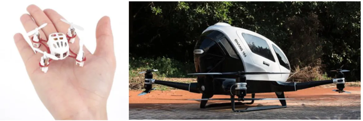
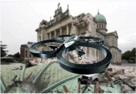
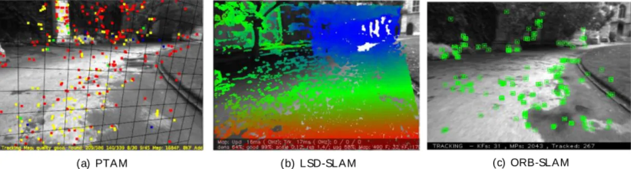
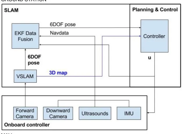
(13) FIGURES INDEX Fig. 1. Different sizes of drones. .................................................................................................... 1 Fig. 2. MAV put to use in a mission inside a ruined building. ............................................ 4 Fig. 3. Software architecture of the ISLAMAV Project: red modules correspond with out of the scope work; the blue modules are the ones implemented in this thesis. .............................................................................................................................................. 5 Fig. 4. Hummningbird drone carrying a Hokuyo laser sensor (Galton et al., 2009). 8 Fig. 5. Schematic of the sensing, control and planning architecture (Galton et al., 2009). .............................................................................................................................................. 9 Fig. 6. High-cost MAV with a RGB-D camera mounted on its base (Bachrach et al., 2012). .............................................................................................................................................. 9 Fig. 7. System overview of the work in. (Achteleik et al., 2011). ................................... 10 Fig. 8. Architecture of the system proposed in (Engel, 2011). ....................................... 11 Fig. 9. Bebop drone (a) vs AR.Drone 2.0 (b) of Parrot. ..................................................... 12 Fig. 10. VSLAM algorithms put to use for this work. Images from (Mur-Artal and Tardós et al., 2015). ................................................................................................................ 14 Fig. 11. Bebop Drone from Parrot ................................................................................................ 17 Fig. 12. Hardware and communications architecture.............................................................. 18 Fig. 13. Software architecture ..................................................................................................... 19 Fig. 14. Software architecture overview. ................................................................................ 20 Fig. 15. Rviz performance. ............................................................................................................ 21 Fig. 16. Kinect camera by Microsoft, a RGB-D camera model........................................... 23 Fig. 17. Stereo pair ............................................................................................................................ 24 Fig. 18. Scale ambiguity problem ................................................................................................. 25 Fig. 19. Principles of stereo vision............................................................................................. 25 Fig. 20. Types of monocular VSLAM ........................................................................................ 27 Fig. 21. Initilization of PTAM ....................................................................................................... 29 Fig. 22. PTAM performance .......................................................................................................... 29 Fig. 23. Map built by PTAM .......................................................................................................... 30 Fig. 24. Overview of the PTAM algorithm ................................................................................ 30 Fig. 25. ORB-SLAM map built indoors ..................................................................................... 32 Fig. 26. ORB-SLAM map built outdoors ................................................................................... 32 Fig. 27. Overview of the ORB-SLAM algorithm .................................................................... 33 Fig. 28. World-camera frame transformation ............................................................................ 34 Fig. 29. Video stream and inverse depth map of LSD-SLAM. .......................................... 34 Fig. 30. Results of LSD-SLAM. The first picture represents the translation of MAV's camera around a room. The second one represents the results of the translation around the same room and along two corridors. .............................................................. 35 Fig. 31. Overview of the LSD-SLAM algorithm. .................................................................... 36 Fig. 32. Displayed results of a test flight. ................................................................................ 42 Fig. 33. Closer view of the previous figure. Some lines were added to the picture to mark the values of the speed and time. .......................................................................... 42 Fig. 34. Delay correction ............................................................................................................... 45.
(14) Fig. 35. Implementation of the EKF. The a) diagram represents the system when the video stream is being received, so all models are being used along with the scale calculator. If the system detects that the video stream is frozen, the EKF will only implement the prediction and NAVDATA correction model, as in b). ........................................................................................................................................................ 46 Fig. 36. Schematics of a PID control. ......................................................................................... 47 Fig. 37. At the left, a P control performance. At the right, the same but adding a derivative term. ........................................................................................................................ 49 Fig. 38. At the left, a PD controller performance. At the right, the same but adding a integral term. ............................................................................................................................ 49 Fig. 39. PID controller blocks diagram. ................................................................................... 49 Fig. 40. Information given by the PID controller main script. ........................................ 50 Fig. 41. Ground truth system.......................................................................................................... 51 Fig. 42. Bebop drone with both coloured circles incorporated as markers for the ground truth system. ................................................................................................................................ 52 Fig. 43. Measurements from the ceilling camera ..................................................................... 52 Fig. 44. Tracking of the flight of the drone. Blue crosses represent the locations of the blue circle and the green crosses the locations of the green one. The purple crosses represent the calculated center of the MAV.................................................. 54 Fig. 45. Flight of the drone tracked with homogenous transforms printed. ............. 54 Fig. 46. Set of pictures taken to calibrate the camera. ............................................................ 55 Fig. 47. Selecting the four corners of the chessboard. ............................................................ 56 Fig. 48. All squares recognized. .................................................................................................... 56 Fig. 49. Reprojection error without corner recalculation ....................................................... 57 Fig. 50. Reprojection error with corner recalculation. ............................................................ 57 Fig. 51. Display of intrinsics and extrinsics. .......................................................................... 59 Fig. 52. Difference between original image and its undistorted version. .......................... 59 Fig. 53. Performance of the system using each of the VSLAM methods. Several tests were accomplished, each of them represented as a coloured line. The red dots shape represents the ground-truth tracking. ............................................................... 61 Fig. 54. Results obtained with an initialization stage. The blue line represents the estimated tracking of the drone, while the red dots shape represents the ground truth tracking. ........................................................................................................... 63 Fig. 55. Comparison between the estimated yaw orientation and the tracked by the ground truth. ............................................................................................................................. 64 Fig. 56. Closer look to the results presented in the previous figure. ........................... 65 Fig. 57. Followed vs. desired tracks in red and blue respectively................................. 66 Fig. 58. Comparative of the results achieved when using just the predictor model with the results achieved using the predictor and NAVDATA correction models –blue and green line respectively–. .................................................................. 68 Fig. 59. Comparative of the results achieved when using just the VSLAM correction model with LSD-SLAM and ORB-SLAM algorithms –blue and green line respectively–. ............................................................................................................................ 69 Fig. 60. Comparative of the results achieved when using just the VSLAM correction model with LSD-SLAM and ORB-SLAM algorithms –blue and green line respectively–; the predictor and NAVDATA correction models –in cyan– and all the models together –in black–. ................................................................................... 70 Fig. 61. Flowchart of the EKF node. .......................................................................................... 73 Fig. 62. Flowchart of the PID controller node. ...................................................................... 74.
(15) Fig. Fig. Fig. Fig. Fig.. 63. System using LSD-SLAM nodes tree ......................................................................... 75 64. System using ORB-SLAM nodes tree ........................................................................ 75 65. Dynamic configuration. .................................................................................................. 83 66. Comparison of both stages of ORB-SLAM. .............................................................. 85 67. Free Flight 3 android application interface. .......................................................... 86.
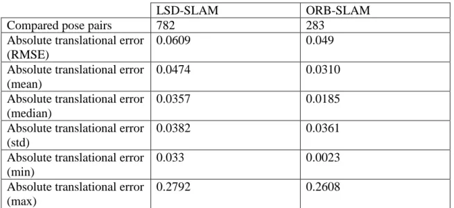
(16) TABLES INDEX Table 1. Comparison between both monocular VSLAM algorithms. The results are given in meters. .......................................................................................................................... 37 Table 2. Results without initialization stage. Error results are given in centimeters. ........................................................................................................................................................ 62 Table 3. Results with an initialization stage. Error results are given in centimeters. ........................................................................................................................................................ 64 Table 4. Errors in the yaw measurements. The results are expressed in degrees. . 66 Table 5. Error between the desired track and the followed by the drone, given in centimeters. ............................................................................................................................... 67 Table 6. Comparison between the performance of the system using only the predictor model and the fusion of the predictor and the NAVDATA correction model............................................................................................................................................ 68 Table 7. Comparison between the performance of the system using only the VSLAM correction model putting to use each of the VSLAM algorithms studied in this work.............................................................................................................................................. 69 Table 8. Validation of data fusion. Errors given in centimetres. .................................... 70 Table 9. Equipment budget (VAT included), presented in euros. .................................. 79 Table 10. Professional fees (gross salary), expressed in euros. ..................................... 80 Table 11. Total cost, expressed in euros. ................................................................................. 80.
(17) Introduction. CHAPTER 1: INTRODUCTION 1.1. Rise of MAVs Drones are fast, agile and versatile robots that can be implemented in a wide spectrum of projects. Due to it and the tendency of the technology to the miniaturization, these robots are living a golden age of development. It is possible to find drones from the ones that can be held in one hand to others that can carry a person as payload. Specifically, MAVs have become an important tool not only in the military domain, but also in civilian environments. Particularly quadcopters are becoming more popular, especially for observational and exploration purposes in indoor and outdoor environments, but also for data collection, object manipulation or simply as high-tech toys.. Fig. 1. Different sizes of drones.. There are numerous examples where MAVs are successfully used in practice, for example for exploratory tasks such as inspecting the damaged nuclear reactors in Fukushima in March 2011, and for aerial based observation and monitoring of potentially dangerous situations, such as protests or large scale sport events. There are however many more potential applications: a swarm of small, light and cheap quadcopters could be deployed to find survivors in collapsed buildings without risking human lives. Equipped with high-resolution cameras, MAVs could also be used as flying photographers, providing aerial based videos of sport events or simply taking holiday photos from a whole new perspective. The main advantage of these robots is that they are unmanned, so they perform missions that are too “dull, dirty or dangerous”. Furthermore, having a flying behaviour similar to a traditional helicopter, a quadrocopter is able to land and start vertically, stay perfectly still in the air and move in any given direction at any time without having to turn first. This enables quadrocopters –contrary to traditional airplanes– to manoeuvre in extremely constrained indoor spaces such as corridors or offices, and makes them ideally suited for stationary observation or exploration in obstacle-dense or indoor environments.. 1.
(18) Visual SLAM Algorithms for Aerial Robots The growing research on MAVs and the consequent improvement of technologies like microcomputers and onboard sensor devices has increased the performance requirements of such kind of systems. Enabled by GPS and MEMS inertial sensors, MAVs that can fly in outdoor environments without human intervention have been developed. Unfortunately, most indoor environments remain without access to external positioning systems, and autonomous MAVs are very limited in their ability to operate in these areas.. 1.2. Key Challenges In the ground robotics domain, combining wheel odometry with sensors such as laser range-finders, sonars, or cameras in a probabilistic SLAM (Simultaneous Localization and Mapping) framework has proven very successful. Many algorithms exist that accurately localize ground robots in large-scale environments; however, experiments with these algorithms are usually performed with stable, slow moving robots, which cannot handle even moderately rough terrain. Unfortunately, mounting equivalent sensors onto a MAV and using an existing SLAM algorithm does not result in the same success. MAVs face a number of unique challenges that make developing algorithms for them far more difficult than their indoor ground robot counterparts. The requirements and assumptions that can be made with flying robots are sufficiently different that they must be explicitly reasoned about and managed differently. These are the main key challenges when developing autonomous navigation systems for MAVs: Limited Sensing Payload. MAVs have a maximum amount of vertical thrust that they can generate to remain airborne, which severely limits the amount of payload available for sensing and computation compared to similar sized ground vehicles. This weight limitation eliminates popular sensors such as SICK laser scanners, largeaperture cameras, high-fidelity IMUs, RGB-D cameras or even the management of a stereo system. Instead, indoor air robots must rely on lightweight Hokuyo laser scanners, micro cameras and lower-quality MEMS-based IMUs, which generally have limited ranges, fields-of-view and are noisier compared to their ground equivalents. Limited Onboard Computation. Despite the advances within the community, SLAM algorithms continue to be computationally demanding even for powerful desktop computers and are therefore not usable on today’s small embedded computer systems that might be mounted onboard MAVs. The computation can be offloaded to a powerful ground-station by transmitting the sensor data wirelessly; however, communication bandwidth then becomes a bottleneck that constrains sensor options. For example, camera data must be compressed with lossy algorithms before it can be transmitted over wireless links, which adds noise and delay to the measurements. The delay is in addition to the time taken to transmit the data over the wireless link. The noise from the lossy compression artefacts can be particularly damaging for feature detectors that look for high frequency information such as corners in an image. Additionally, while the delay can often be ignored for slow moving, passively stable ground robots, MAVs have fast and unstable dynamics, making control under large sensor delay conditions impossible. 2.
(19) Introduction Indirect Relative Position Estimates. Air vehicles do not maintain physical contact with their surroundings and are therefore unable to measure odometry directly, which most SLAM algorithms require to initialize the estimates of the vehicle’s motion between time steps. Although one can compute the relative motion by doubleintegrating accelerations, lightweight MEMs IMUs are often subject to unsteady biases that result in large drift rates. We must then recover the vehicle’s relative motion indirectly using exteroceptive sensors –sensors that determine the measurements of objects relative to the robot's frame of reference–, and computing the vehicle’s motion relative to reference points in the environment. Fast Dynamics. MAVs have fast dynamics, which results in a host of sensing, estimation, control and planning implications for the vehicle. When confronted with noisy sensor measurements, filtering techniques such as Kalman Filters are often used to obtain better estimates of the true vehicle state. However, the averaging process implicit in these filters mean that multiple measurements must be observed before the estimate of the underlying state will change. Smoothing the data generates a cleaner signal, but adds delay to the state estimates. While delays may have insignificant effects on vehicles with slow dynamics, the effects are amplified by the MAV’s fast dynamics. Additionally, the named “Ground effect” may occur when flying close to the ground, ceiling or walls. Need to Estimate Velocity. The underdamped nature of the dynamics model implies that simple proportional control techniques are insufficient to stabilize the vehicle, since any delay in the system will result in unstable oscillations. For this reason, we must add damping to the system through the feedback controller, which emphasizes the importance of obtaining accurate and timely state estimates for both position and velocity. Traditionally, most SLAM algorithms for ground robots completely ignore the velocity states. MAVs do not incorporate sensors that can measure the current speed, so it has to be estimated by other means. For instance, the Bebop Drone (used in this work) puts to use a vertical camera placed in its bottom to estimate the horizontal velocity. In order to enable the drone to keep its position in spite of wind, an optical-flow based motion estimation algorithm utilizing the full 60 fps from the floor camera is performed onboard, estimating the drone’s horizontal speed. The exact way these values are determined however is not documented. Constant Motion. Unlike ground vehicles, a MAV cannot simply stop and perform more sensing when its state estimates have large uncertainties. Instead, the vehicle is likely to be unable to estimate its velocity accurately, and as a result, it may pick up speed or oscillate, degrading the sensor measurements further. Thus, planning algorithms for air vehicles must not only be biased towards paths with smooth motions, but must also explicitly reason about uncertainty in path planning. 3D Motion. Finally, MAVs operate in a truly 3D environment since they can hover at different heights. While it is reasonable for a ground robot to focus on estimating a 2D map of the environment, for air vehicles, the 2D cross section of a 3D environment can change drastically with height and attitude, as obstacles suddenly appear or disappear.. 3.
(20) Visual SLAM Algorithms for Aerial Robots. 1.3. The ISLAMAV Project This work is part of the ISLAMAV Project –developed by the RobeSafe Group of the Electronics Department of the University of Alcalá– whose final goal is the development of a MAV-based inspection system that will recognize indoor ruined or semi-ruined buildings in the context of rescue missions. This kind of environments will be unknown and GPS-denied, so the MAV will have to trust in its own onboard sensors. In order to achieve this goal several measurements from different sensors are fused to improve the pose estimation for MAVs in indoor environments. As a strategy of the fusion algorithm, each of the sensors must be able to provide its own pose estimation to endow the system with some redundancy that allows it to work in different environmental conditions.. Fig. 2. MAV put to use in a mission inside a ruined building.. The software architecture of the whole navigation system proposed in the ISLAMAV Project is shown in Fig. 3. As it can be seen, the SLAM system fuses the information of three sensorial systems: a scan-matcher module based on laser measurements, a VSLAM system based on a monocular camera, and the rest of onboard sensors (IMU, ultrasounds, etc.). The usage of monocular VSLAM is justified because due to their low weight and cost, monocular cameras are included in most of the commercial MAVs. However, its usage is constrained to environments with specific features and lighting conditions, and so a laser sensor will improve the performance of the SLAM system in indoor environments due to its high working rate and its direct and accurate range detection. One of the requirements of the ISLAMAV Project is that the sensorial system has to be modular and configurable. So, this thesis focuses on the development of the monocular VLSAM module and the fusion with the onboard sensor measurements using an Extended Kalman Filter.. 4.
(21) Introduction. Fig. 3. Software architecture of the ISLAMAV Project: red modules correspond with out of the scope work; the blue modules are the ones implemented in this thesis.. To face the computational requirements, the system is composed of a flight and a ground unit, so that code can be distributed in different nodes using ROS (Robot Operating System). The ground unit will be implemented as a laptop with ROS installed on it. We had to divide the system in these two parts due to some problems related with the use of MAVs explained before: limited onboard computation and limited sensing payload. The VSLAM algorithms that were chosen in order to calculate the pose estimation (along with the measurements from the other onboard sensors) and the map of the environment are: LSD-SLAM and ORB-SLAM. Both of them are put to use so a comparison between the two methods can be performed. The differences between them, as well as the strengths and weaknesses will be explained in Chapter 5. One of the main problems of monocular camera VSLAM algorithms is the fact that it cannot calculate the scale of the data of tracking and mapping. It leads to a system that is not working with real-scale data, what could affect the integrity of an aerial robot. To solve this problem, our system uses the data from other onboard sensors to calculate the dynamic scale of the SLAM to return the real-time pose of the MAV without scale ambiguity. In this work, up-to-date VLSAM algorithms are fused with measurements from other onboard sensors (IMU, sonar, vertical camera, etc.) to solve the SLAM problem in complex indoor environments and robustly estimate the 6DOF (six-degrees-of freedom) pose of the MAV, using a distributed system with a flight unit and a ground station. In order to fuse measurements from the VSLAM algorithms and other onboard sensors, an EKF is implemented. Moreover, the system is able to calculate the dynamic scale of the measurements, what makes it a scale-aware system. Due to it, the EKF and the control stage work with real scaled data, in contrast to other monocular VSLAM systems. 5.
(22) Visual SLAM Algorithms for Aerial Robots The problem of autonomous indoor MAV localization was addressed as a software challenge, focusing on high-level algorithms integration rather than specific hardware. For this reason, we use a low-cost commercial platform with minor modifications and an open-source development platform (ROS), so drivers of sensors and some algorithms can be used without development.. 1.4. Problem Statement and Initial Objective The initial objective of this work is to study different monocular VSLAM techniques and its ability to be implemented in aerial robots in order to estimate their 6DOF position, taking into account the special constraints of this kind of platforms. The obtained pose estimation will be scaled using other onboard measurements, and finally will be fused with these measurements to improve the estimation. Besides, a position controller will be designed in order to guide the MAV to commanded target positions. Finally, another important objective is to implement the system in a real robotic platform to obtain experimental results that can be used to validate the study.. 1.5. Outline The remaining sections of this document are organized as follows: In Chapter 2, a study of the state of the art is performed in order to explain some related work and to place this work in the field of study. Chapter 3 presents the formulated hypothesis for this work. The necessary steps followed in order to validate this hypothesis are mentioned. In Chapter 4, an overview of the system and the two sides of the architecture – both hardware and software– are explained. Chapter 5 talks about the VSLAM algorithms and specifies which ones will be used for this work and why. A comparison performed by means of a benchmark is presented. In Chapter 6, the data fusion and how it is achieved in this work is explained. All the models implemented in our EKF are described in detail. Chapter 7 describes the PID controller developed in this thesis. Chapter 8 explains the results obtained in real experiments, comparing estimation and tracking from a ground truth. How this ground truth system was elaborated is explained too. In Chapter 9, the main conclusions and future work lines are summarized. The last sections correspond to the diagrams, specifications, budget, user guide and bibliography of this work. The thesis also includes an appendix where the achieved additional activities are listed and explained.. 6.
(23) State of the Art. CHAPTER 2: STATE OF THE ART In this chapter a brief review of the main techniques used to develop autonomous navigation systems for aerial robots is presented. This study justifies the use of monocular cameras as the main sensor for navigation over other proposals for low-cost MAVs. It also includes a description of the closest related projects in order to contextualize the developed work.. 2.1. Autonomous navigation of MAVs Since the rise of use and research in the field of MAVs, there have been numerous efforts to fly quadrocopters autonomously. Most of these efforts have been made for outdoor situations. In this kind of environments the obstacles density is lower and the GPS signal will be enabled in almost all situations. For instance, in (Mellinger et al., 2011) an algorithm for addressing the controller design and the trajectory generation for a quadrotor manoeuvring in three dimensions is explained. Other authors use GPS-based methods in order to localize the drone in outdoor environments (Vago et al., 2015). Other applications are developed thinking in animal-based algorithms as in (Senanayake et al., 2016) (Lindsey et al., 2011) (Kushleyev et al., 2012) that performed a system based on a collaborative swarm of aerial robots. However, in this work the system will have to accomplish a simultaneous localization and mapping of indoor, unknown, and GPS-denied environments. The autonomous navigation of MAVs in this kind of environments is even today an open area of research. It is not possible to use the classic odometry systems –based on encoders– of ground robots for MAVs. Due to it, this kind of systems must be replaced by inertial systems so new sensor-based strategies for the localization have been developed. Besides, the absence of a previous map of the environment makes mandatory the implementation of simultaneous localization and mapping (SLAM) solutions, as well as robust state estimation and control methods. For these solutions, the use of different sensors has been proposed in the literature as: range laser scanners (Grzonka et al., 2009); monocular cameras (Achtelik et al., 2012); stereo cameras (Fraundorfer et al., 2012) or RGB-D sensors (Huang et al., 2011) (Bylow et al., 2013). As it has been explained before, one of the main problems when using this kind of sensors in MAVs is the limited sensing payload. The drone put to use must be able to fly steady carrying the chosen sensor. This is not possible to most of the commercial low-cost drones and a specific and more expensive MAV may be used for this situation. In addition, such drone able to carry a heavy payload is usually too big to be managed in indoor environments. The drone’s size may be a problem due to several reasons: it could be dangerous if flying near humans, and the strength of the thrusters could be enough to not allow the MAV to fly steady near walls or the floor due to the “ground effect”. So, the need to use small MAVs in indoor environments requires selecting the most appropriate sensors. Monocular cameras are light, small and cheap and indeed they are usually included in most low-cost commercial drones. Their inherent scale. 7.
(24) Visual SLAM Algorithms for Aerial Robots ambiguity problem can be solved by taking advantage of other typical onboard sensors such as IMU or ultrasound sensors. That is the reason why this proposal will be explored in this thesis in order to solve the SLAM problem in MAVs.. 2.2. Related Projects In this section, some works whose framework is close to the one treated on this thesis will be explained. They correspond to the main successful indoor navigation systems for MAVs developed in the last years. Some of them use heavy sensors that cannot be used in small low-cost MAVs, but propose software architectures that have inspired this work. Others propose monocular camera-based navigation systems and will be contextualized with respect to this thesis. One of the main works that served as a reference for the ISLAMAV project approach –within this thesis fits– is the one developed by Galton (Galton et al., 2009) in the Massachusetts Institute of Technology. This work presents a solution for enabling a quadrotor helicopter, equipped with a laser rangefinder sensor, to autonomously explore and map unstructured and unknown indoor environments. An overview of their solution to the key problems, including a multilevel sensing and control hierarchy, a high-speed laser scan-matching algorithm, an EKF for data fusion, a high-level SLAM implementation, and an exploration planner are provided. Finally, they show experimental results demonstrating the helicopter's ability to navigate accurately and autonomously in unknown environments. In this work, the authors fuse measurements from a Hokuyo range laser scanner with the ones from the IMU. Thanks to it, they achieve a robust SLAM system that can face adverse situations as bad illuminated environments. For this implementation, they have to use a drone that is able to carry a heavy payload –Hummingbird from Ascending Technologies, as seen in Fig. 4–, a much more expensive hardware architecture than the proposed for this thesis.. Fig. 4. Hummningbird drone carrying a Hokuyo laser sensor (Galton et al., 2009).. On the other hand, although their hardware platform target is not the same as ours, they have developed an autonomous system able to fly and avoid obstacles thanks to an estimation of the drone’s relative position within its environment and a controller. The software architecture of the navigation system is shown in Fig. 5, and it has served as reference for the autonomous navigation side of this thesis.. 8.
(25) State of the Art. 2. Bachrach et. al.. 1 I ntroduction Unmanned air vehicles (UAVs) rely on accurate knowledge of their position for decision-making and control. As a result, considerable investment has been made towards improving the availability of global positioning infrastructure, including Fig. 5. Schematic of the sensing, control and planning architecture (Galton et al., 2009). utilizing satellite-based GPS systems and developing algorithms to use existing RF signals such as later, WiFi.another However, indoor in environments Few years workmost is proposed (Bachrach et and al., many 2012), parts a newof the system for visual odometry and mapping using an RGB-D camera and its application to the urban canyon remain without access to external positioning systems, limiting autonomous flight. By leveraging UAVs resultstofrom recent state-of-the-art ability of current autonomous fly through these areas. algorithms and hardware, their system enables 3D flight in cluttered environments using only onboard Localization using sonar ranging (Leonard and Durrant-Whyte, 1991), laser sensor data. All computation and sensing required for local position control are ranging (Thrun 2000)reducing or camera (Se on et al., 2002) wireless has been used experformed onboardettheal., vehicle, the sensing dependence unreliable links. tremely even successfully on a number of ground robots and is now a comHowever, with accurate 3D sensing and position estimation, someessentially parts of the modity technology. we have developed algorithms MAV that flight in environment have more Previously, perceptual structure than others, leading to state for estimates vary in accuracy across the environment. If the vehicle plans a path without regard cluttered environments using laser range finders (Bachrach et al., 2009a) andtostereo how well it (Achtelik can localizeetitself path,range it runsfinders the risk that of becoming lost or available worse. cameras al., along 2009).that Laser are currently in The authors show how the Belief Roadmap (BRM) algorithm (Prentice et al., 2008) –a form factors appropriate for use on a MAV are very high precision, but only provide belief space extension of the Probabilistic Roadmap algorithm– can be used to plan range trajectories measurements a plane sensor. Since thesecamera. sensorsThey can only vehicle that along incorporate the around sensing the model of the RGB-D detect objects that intersect thesystem sensing they are most useful in environments evaluate the effectiveness of their forplane, controlling a quadrotor, demonstrate its characterized by vertical so in more complexand scenes. use for constructing detailedstructures, 3D maps and of less an indoor environment discuss its limitations.. 6. High-cost withair a RGB-D camera mounted on its base (Bachrach et al., 2012). Fig. 1Fig. Our quadrotorMAV micro vehicle (MAV). The RGB-D camera is mounted at the base of the vehicle, tilted slightly down.. Although the system is a SLAM solution for indoor environments for MAVs, there is a huge difference between this work and the one proposed in this thesis: the hardware architecture. dronecameras put to use lift a upon RGB-D camera, which weighs Structured light The RGB-D arecanbased stereo techniques, and thus typically more than a kilogram. Furthermore, although the position control and the. share many properties with stereo cameras. The primary differences lie in the range and spatial density of depth data. Since RGB-D cameras illuminate a scene with a structured light pattern, they can estimate depth in areas with poor visual texture 9 but are range-limited by their projectors. This paper presents our approach to providing an autonomous micro air vehicle with fast and reliable state estimates and.
(26) Visual SLAM Algorithms for Aerial Robots relative localization estimation is made offboard –that means, performed by a ground station– the SLAM is computed inside the drone, that is, performed by the onboard processor. Both features make the MAV a high-cost platform, which is the opposite of the idea suggested in this thesis. On the other hand, the fusion of a visual sensor with measurements from the IMU makes this work a close relative and a source of ideas for the system developed in this thesis.. Fig. 7. System overview of the work in. (Achteleik et al., 2011).. The research presented in (Achteleik et al., 2011) is closer to the research made for this thesis than the previous ones. The SLAM system fuses information from the monocular camera with measurements from the IMU. The authors give a solution to overcome the issue of having a low frequency onboard visual pose update versus the high agility of an MAV. This is solved by filtering visual information with inputs from inertial sensors, as can be seen in Fig. 7. Then, as their system is based on monocular vision, they present a solution to estimate the metric visual scale aid of an air pressure sensor. All computation is running onboard and is tightly integrated on the MAV to avoid jitter and latencies. This framework enables stable flights indoors and outdoors even under windy conditions.. 10.
(27) State of the Art There are two main differences between both works that must be highlighted. As seen in the two previous reviewed works, the authors put to use expensive MAVs in order to reach their goals. In (Galton et al., 2009) and (Bachrach et al., 2012), they were used to lift a heavy load, while for the work described in this section this kind of drone is implemented due to its onboard computer. In (Achteleik et al., 2011) the authors use a Pelican quadrocopter from Ascending Technologies. The other remarkable difference is –as just said– that they perform all the system onboard, while in our case all the computing has to be done by an external ground system due to the limitations of the platform. Therefore, they need a powerful computer on the drone. Another difference is the visual SLAM technique put to use for this system. The authors chose PTAM (Klein et al., 2007) as the algorithm used for the visual localization and mapping, which is an old and not very reliable technique. In this thesis newer, more efficient and more robust algorithms have been chosen. Furthermore, the method applied in this work in order to calculate the absolute scale for the monocular VSLAM estimations employs an onboard pressure sensor. The measurements from this sensor are very noisy and prone to drift due to changing weather conditions –the usage of this sensor was considerate for our work but was declined after several tests due to these problems–. Therefore, the authors had to design an EKF in order to fuse all data from different sensors and incorporate the scale and pressure sensor drift in the states. Thanks to it, they could achieve good results despite the noisy sensors. Finally, in (Engel, 2011) the authors developed a system that enables a quadrocopter to localize and navigate autonomously in previously unknown and GPSdenied environments. This approach uses a monocular camera onboard the quadrocopter and does not require artificial markers or external sensors. Their approach consists of three main components, as it can be seen in Fig. 8. Firstly, the authors used a monocular, keyframe-based simultaneous localization and mapping (SLAM) system for pose estimation. Secondly, they implemented an extended Kalman filter, which includes a full model of the drone’s flight and control dynamics to fuse and synchronize all available data and to compensate for delays arising from the communication process and the computations required. Finally, they used a PID controller to control the position and orientation of the drone.. Fig. 8. Architecture of the system proposed in (Engel, 2011).. Furthermore, the authors proposed a method to estimate the absolute scale of the generated visual map from inertial and altitude measurements, which is based on a statistical formulation of the problem. Following a maximum likelihood (ML) approach, they derive a closed-form solution for the ML estimator of the scale.. 11.
(28) Visual SLAM Algorithms for Aerial Robots The authors implemented their approach on a real robot and extensively tested and evaluated it in different real-world environments. As hardware platform they used the Parrot AR.Drone; demonstrating what can be achieved with modern, low-cost and commercially available hardware platforms as tool for robotics research. In their approach, all computations are performed on a ground station, which is connected to the drone via wireless LAN. This work is the main reference for the work developed in this thesis. It makes this research the closest one in the investigation concerning. Due to its implementation in low-cost MAVs, they were not able to carry heavy sensors as RGB-D cameras and/or range laser scanners. It forced them to use the available sensors in most of commercial drones –monocular cameras and the IMU–. Although there are several similarities between this work and this thesis, there are some differences too. The most important contributions of this thesis are: . Platform: While the platform used in (Engel, 2011) is the AR.Drone1 the one chosen for this thesis is the Bebop drone2. The main improvements of the Bebop are its higher stability and lower dimensions. The flight of the Bebop drone is steadier than the one of the AR.Drone, something crucial when working with visual SLAM. Furthermore, a stable flight can avoid crashes when working with these aerial robots that have such fast dynamics. Other important improvement is the performance of the camera. Not only the field of view (FOV) has been increased but the resolution of the video. It allows the VSLAM algorithm to estimate the drone’s position in a better way without pre-processing the image – with the delay that it implies–.. a). b). Fig. 9. Bebop drone (a) vs. AR.Drone 2.0 (b) of Parrot.. . 1 2. Visual SLAM technique: The VSLAM algorithm chosen in (Engel, 2011) is PTAM (Klein et al., 2007). This is an out-dated algorithm that causes drifts and errors when applied to fast platforms such as aerial robots. One of the initial objectives of this thesis was to study the ability of different up-to-date visual SLAM methods to be applied in aerial robots, and so this is one of the items in which an effort has been done.. http://www.parrot.com/es/productos/ardrone-2/ http://www.parrot.com/products/bebop-drone/ 12.
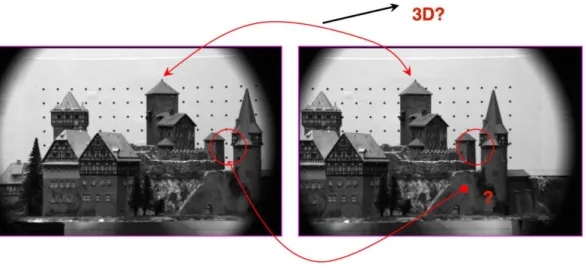
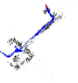
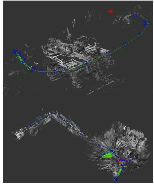
(29) State of the Art The next section briefly reviews recent visual SLAM techniques in order to choose the ones to be studied and applied in the SLAM system proposed in this thesis.. 2.3. Visual SLAM techniques There are different sensors that can be implemented in a Visual SLAM system. While some of them are typically implemented in ground robots due to its weight, there are others that can be used in MAVs. As seen before, there are some research or professional-oriented MAVs that can also carry a heavy load and therefore the kind of sensors usually included in ground-robot systems, but this is not the scope of this project. These drones are able to lift such sensors as RGB-D or stereo cameras systems that are able to return not only a video stream but also a depth map of the environment. It simplifies the implementation of a VSLAM system and making it autonomous. However, in light and low-cost MAVs the best solution is to use the included monocular camera. In order to perform the simultaneous localization and mapping of the environment by means of visual information, the process of visual odometry (VO) must be accomplished. Visual odometry is the process of determining the position and orientation of a robot by analysing the associated camera images, thus, to estimate the 6DOF position of the MAV. The VO approaches can be classified into two main categories based on the number of cameras adopted: monocular and stereo VO methods. A stereo pair is applied as minimum number configuration of cameras for solving scale ambiguity problem –as will be explained in Chapter 5- in order to carry on the stereo visual odometry (Brand et al., 2014). However, stereo camera systems are not the focus of this work but the monocular ones. In the literature, (Klein et al., 2007) has proposed the most representative monocular keyframe-based tracking and mapping system, PTAM (Parallel Tracking And Mapping), for real time pose estimation applications (Fig. 10.a). In (Forster et al., 2014) a semi-direct monocular visual odometry algorithm is also presented, i.e. SVO (Semi-direct Visual Odometry). This algorithm can be implemented on an onboard embedded computer –in the case of the paper, in an Odroid U2– which runs at 55 FPS and outputs a sparse 3D reconstructed environment model. In (Newcombe et al., 2011), the work DTAM (Dense Tracking And Mapping), a real-time probabilistic monocular pose estimation method for 3D dense environment reconstruction is proposed. In (Engel et al., 2014 a) the authors describe a direct monocular simultaneous localization and mapping algorithm for building consistent, semi-dense reconstructions of the environments, the LSD-SLAM method (Fig. 10.b). Finally, in (Mur-Artal et al., 2015) a keyframe-based monocular SLAM system with ORB features that can estimate the 6DOF pose and reconstruct a sparse environment model is presented (ORB-SLAM – Fig. 10.c).. 13.
(30) Visual SLAM Algorithms for Aerial Robots. 2.2. Visual Odomet ry (a) PTAM. (a) PTAM. (b) LSD-SLAM. (b) LSD-SLAM. (c) ORB-SLAM. Figure 2.5: T he well-known monocular VO syst ems. Images from (Mur-Art al Tardós, 2015). Fig. 10. VSLAM algorithms put to use for this work. and Images from (Mur-Artal and Tardós et al., 2015).. Especailly, (St rasdat et al., 2011) has implement at ed a double window optimizat ion framework for const ant -t ime visual stereo SLAM, i.e. ScaViSLAM 2. As int roduced in chapter 1, a typical UAV has limit ed size, payload, The two last algorithms –LSD-SLAM and ORB-SLAM– are two of the best comput at ion capability, power supply and expanded mounting space for VSLAM methods due to their robustness other and sensors. performance. However, thesearerecent Alt hough many st ereo cameras available to be sold on t he marketA s current ly, e.g. description Skybot ix VI-sensor methods have not been applied to aerial commercial robots yet. detailed and3, Point Grey Bumblebee24 and VisLab 3DV-E5, as shown in Fig. 2.8. However, t he high cost comparison of the three methods shown in (e.g. Fig.Skybotix 10 –PTAM, LSD-SLAM and ORBVI-sensor and VisLab 3DV-E), big weight (e.g. Point Grey (c) ORB-SLAM SLAM– is shown in Chapter 5. Also, its application to aerial navigation is explored in Bumblebee2 and VisLab 3DV-E) or incompat ible communicat ion interface Figure 2.5: T he well-known monocular VO syst ems. Images from (Mur-Art al (e.g. Point Grey Bumblebee2) reduce a number of potential university or this thesis. and Tardós, 2015).. 2. ht t ps:/ / git hub.com/ st rasdat / ScaViSLAM/. Especailly, (St rasdat et al., 2011) has implement at ed a double window op3 ht t p:/ / www.skybot ix.com/ 4 timizat ion framework for const ant -t ime visual stereo SLAM, i.e. ScaViSht t p:/ / www.pt grey.com/ 5 LAM 2. As int roduced in chapter 1, a typical UAV has limit ed payload, ht tsize, p:/ / vislab.it / product s/ comput at ion capability, power supply and expanded mounting space for other sensors. Alt hough many st ereo cameras are available to be sold on t he commercial market s current ly, e.g. Skybot ix VI-sensor 3, Point Grey Bumblebee24 and VisLab 3DV-E5, as shown in Fig. 2.8. However, t he high cost (e.g. Skybotix VI-sensor and VisLab 3DV-E), big weight (e.g. Point Grey Bumblebee2 and VisLab 3DV-E) or incompat ible communicat ion interface (e.g. Point Grey Bumblebee2) reduce a number of potential university or 2. ht t ps:/ / git hub.com/ st rasdat / ScaViSLAM/ ht t p:/ / www.skybot ix.com/ 4 ht t p:/ / www.pt grey.com/ 5 ht t p:/ / vislab.it / product s/. 3. 18. 14. 18.
(31) Hypothesis and Methodology. CHAPTER 3: HYPOTHESIS AND METHODOLOGY After showing the problem statement of this work and performing a background research about related projects, we are in the position to formulate the hypothesis that will be developed in this thesis, and to set a series of specific objectives from the initial statement and the methodology to reach them.. 3.1. Hypothesis formulation After the study of the state of the art in MAVs autonomous navigation, it has been found that one of the main problems when developing reliable SLAM systems is the payload limitation, which restricts the kind and number of sensors to be used. For indoor applications, where the size of the drone has to be small and GPS signal is not available, this problem is particularly hard. In these situations it is required to use only light onboard sensors such as monocular cameras or inertial measurement units, but developing robust SLAM systems with this constraints is still a research challenge. The hypothesis of this work is that the application of recent monocular VSLAM techniques to aerial robots is possible by fusing the results with other onboard sensors in order to solve the scale ambiguity problem and to improve the results of the position and map estimation. It is intended to demonstrate this hypothesis on commercial lowcost drones, whose computational onbard power is very limited. For this reason the SLAM system will be executed in a ground control unit, taking into account the delays of the wireless link in the control loop.. 3.2. Method for testing the hypothesis: specific goals In order to achieve a conclusion and to validate the hypothesis some objectives are needed to overcome. These objectives and the methodology to achieve them are the following: . 3. Choose a robot development environment that facilitates the integration of the necessary codes. Robot Operating System (ROS) 3 is a very popular platform today, and one of the most widespread in the research field, why it has been chosen for this work. It allows to create distributed network systems and provides the services expected from an operating system, including hardware abstraction, low-level device control, implementation of commonly-used functionality, message-passing between processes and package management.. http://www.ros.org/ 15.
(32) Visual SLAM Algorithms for Aerial Robots . Perform a research in the area of hardware platforms for drones and its available drivers for ROS. Due to their small size, light weight, low cost and to the possibility of controlling them from a remote station using ROS drivers, two platforms of Parrot will be studied: the AR.Drone and the Bebop drone.. . Perform a research of the available monocular VSLAM algorithms for ROS and select the best ones. As it has been seen in the state of the art, PTAM is a classical monocular VSLAM method that has already been applied to drones. It is available as a ROS package. The two recent methods LSD-SLAM and ORBSLAM are both available as ROS packages too, but they have not been applied neither compared in aerial robots. The three methods will be tested and adjusted using the cameras of the AR.Drone and Bebop drones.. . Study the scale ambiguity problem of the last algorithms and provide a solution that, using other onboard sensors (such as IMU or sonar), will get the real scale of the obtained map.. . Develop an Extended Kalman Filter (EKF) to fuse the VSLAM and onboard sensors measurements in order to improve the estimation of the 6DOF pose of the drone and the local map. To do this, movement and observation models will have to be studied for the drone and its sensors.. . Develop a PID controller that, using the estimated pose of the global SLAM system (output of the EKF), allows the drone to reach position goals.. . Develop a ground-truth system that allows us to validate the estimated pose. A typical ground-truth system for aerial robots, due to their fast dynamics, is a motion capture system. However, as this is not available, a simplification will be designed based on a camera on the ceiling, which will permit to measure some of the variables of the system using an external reference.. . Perform experiments in order to collect enough data to analyse and validate our proposal, calculating the errors and adjusting variables –as the coefficients of the PID controller, the working period of the system, the added Gaussian noise, etc.– to obtain an optimal response of the SLAM system. . Present reviewed results and a conclusion about the hypothesis.. 16.
(33) System Overview. CHAPTER 4: SYSTEM OVERVIEW In this thesis, the problem of autonomous indoor MAV localization is addressed as a software challenge, focusing on high-level algorithms integration rather than specific hardware. For this reason, a low-cost commercial platform with minor modifications and an open-source development platform (ROS) are used, so that drivers of sensors and some algorithms can be used without development. Through this chapter an overview of the whole system is presented, starting with the hardware architecture and the reasons of why the platform put to use was chosen. Some hardware specifications are shown too. Next to it, the software architecture is explained. As said before, the objective is to develop a software system that could perform a SLAM addressing the MAV as a black box. Thus, in this project the most important side of the architecture is the software.. 4.1. Hardware Architecture The quadrotor MAV used for this work –shown in Fig. 11– is the Bebop from Parrot, a lighter (400 gr) and smaller (33x38x3.6cm) drone than the earlier AR.Drone 2.0. The last was also put to use for the performance, but due to its lower flight stability its usage was declined. Bebop MAV can carry up to 200g of payload for about 5 minutes and it is equipped with a frontal “Fisheye” camera. It has another vertical camera, which is used for stabilization and horizontal velocity estimation. Besides, it has an ultrasonic altimeter, a 3-axis accelerometer, 2 gyroscopes and a barometer. It incorporates an onboard controller 8 times more powerful than the one from the AR.Drone 2.0 (dual-core processor Parrot P7), a quad-core graphic processor, flash memory of 8Gb and a Linux distribution. It is controlled via Wi-Fi –it provides its own network– and a SDK is available for application development.. Fig. 11. Bebop Drone from Parrot. 17.
(34) Visual SLAM Algorithms for Aerial Robots This model of drone was chosen between all the low-cost commercial models of MAVs because of its steadiness, something crucial when flying these robots in indoor environments with a big amount of obstacles. Furthermore, a driver for ROS was already developed, as it will be explained in the next section. Although the Bebop comes with some software for basic functionality, it is neither open-source nor easy to modify, and so it is treated as a black box, using only the available W-LAN communication channels to access and control it from a remote station, in this case a laptop, as it is shown in Fig. 12.. Navigation channel Video channel Command channel Flying unit: Bebop drone Ground Station Fig. 12. Hardware and communications architecture. Specifically, these are the inputs/outputs used by the SLAM system that will be executed in the ground station: . Video channel, to receive the video stream of the forwards facing camera, with maximal supported resolution of 640x368 and frame rate of 30fps.. . Navigation channel, to read onboard sensor measurements every 5ms. The data used by the system are: ̅, Ψ ̅, Θ ̅ ). 1. Drone orientation as roll, pitch and yaw angles (Φ ̅̅̅̅̅, ̅̅̅̅̅ 2. Horizontal velocity in drone’s coordinate system (vdx vdy ), calculated onboard by an optical-flow based motion estimation algorithm. 3. Drone height h̅ , obtained from the ultrasound altimeter measurements.. . Command channel, to send the drone control packages, with the desired velocities of x and y axis (in world coordinates); vertical speed and yaw rotational velocity: ̂̇ ) u = (vx ̂, vy ̂, vz ̂, Ψ 18. (1).
(35) System Overview. 4.2. Software Architecture For the development of the software architecture, ROS meta-operating system was put to use –the whole project has been developed for ROS Indigo on Ubuntu 14.04–. ROS implements packages in order to perform different applications for robotics. These packages contain nodes, which could be programmed in C++ or Python. The nodes achieve specific tasks for the whole package. The nodes are communicated by means of topics and messages. In this work topics are mostly used, and represent a channel of information where different nodes could read and/or write. The SLAM system explained in this work consists of three major components: (a) a monocular VSLAM system that obtains a 6DOF pose estimation (and a 3D map of the environment); (b) an Extended Kalman Filter that fuses the last estimation with the navigation data provided by the onboard sensors of the MAV to obtain a robust 6DOF estimation of the position of the robot in the generated map; and (c) a PID controller that allows the MAV to reach goal poses using the estimated position. All of these components will be deeply explained in their corresponding chapters. In the following the implementation in ROS is explained.. Fig. 13. Software architecture. As seen in the previous figure, all the computing is performed in the ground station. In Fig. 14 we show the ROS-based implementation of the system. The drone’s ROS driver (bebop_autonomy) reads the information obtained by the onboard sensors in order to compute the estimation and motion control. The forward camera brings the video stream needed for executing the VSLAM. The downward facing camera allows us to read the horizontal velocities –using an onboard implemented algorithm (Bristeau et 19.
(36) Visual SLAM Algorithms for Aerial Robots al., 2011) –; the ultrasound sensors inform about the distance between the floor and the drone and the IMU brings us direct measurements from gyroscopes and accelerometers. These three last sensors –grouped in the channel hNAVDATA– allow the system to perform the data fusion by means of the EKF. Then, knowing the current estimation of the position and a goal, the PID controller calculates the command u and sends it to the drone through the drone’s driver.. Fig. 14. Software architecture overview.. In Fig. 14, blue blocks represent the packages developed for this thesis, while the red ones are previously programmed packages available for ROS. Thus, the drivers for both of the drones put to use were previously developed –something kept in mind when the drone’s models were chosen– so were the compared monocular VSLAM algorithms. Regarding to this, the work accomplished for this thesis was to learn how to use these packages and to implement them in our system. The tool Rviz –a 3D visualizer developed for ROS– is also implemented in ROS and is used to visualize results and debugging the code. Fig. 15 shows a screenshot of Rviz during an execution of the SLAM system, where the trajectory followed by the drone and the obtained map are shown in red and black respectively. It is possible to display also a video stream, the position estimated by a laser or a topic of type Odometry. This last kind of marker is employed to display the estimation of the system by means of the node odom_publisher –also included in the package of the EKF–. Furthermore, the node robot_tf_publisher replaces the estimated position of the drone from the location of the forwards facing camera to the drone’s centre –which is around 105mm behind in the X axis–. It allows 20.
Figure
+7


Documento similar