Monterrey, Nuevo León a 3 de Junio de 200 3
Lic. Arturo Azuara Flores:
Director de Asesoría Legal del Sistema
Por medio de la presente hago constar que soy autor y titular de la obra
titulada:" A computer-aided framework for manufactura bility
analysis of robot-made assemblies
", en los sucesivo LA OBRA, en virtud de lo cual autorizo a el
Instituto Tecnológico y de Estudios Superiores de Monterrey (EL INSTITUTO)
para que efectúe la divulgación, publicación, comunicación pública, distribución y
reproducción, así como la digitalización de la misma, con fines académicos o
propios al objeto de EL INSTITUTO.
El Instituto se compromete a respetar en todo momento mi autoría y a
otorgarme el crédito correspondiente en todas las actividades mencionadas
anteriormente de la obra.
A computer-aided framework for manufacturability analysis of
robot-made assemblies-Edición Única
Title
A computer-aided framework for manufacturability
analysis of robot-made assemblies-Edición Única
Authors
Olivia Maricela Barrón Cano
Affiliation
ITESM
Issue Date
2003-05-01
Item type
Tesis
Rights
Open Access
Downloaded
19-Jan-2017 05:50:09
Olivia Mariela Barron Cano
Ph.D. Thesis
Instituto Tenologio y de Estudios
Superiores de Monterrey
Campus Monterrey
Graduate Programs of Eletronis, Computer Siene,
Informatis and Communiations
TheommitteemembersherebyreommendthethesispresentedbyOliviaMariela
Barron Cano to be aepted as a partialrequiremente to be admitted tothe Degree
of Dotor of Philosophy in Artiial Intelligene.
Commitee Members
Dr. Jose LuisGordillo Mososo Dr. LuisEnrique SuarSuar
Advisor
Dr. Arturo Molina Gutierrez Dr. JoseManuel Sanhez Gara
Dr. DavidGarza Salazar
Diretor of Graduate Programs of Eletronis,
Computer Siene, Informatis and Communiations
my own researh.
OliviaMariela BarronCano
Monterrey
Ithasbeenproventhatmanufaturingenterprisesouldobtainsigniantsavings,both
intime andmoney,by makinghangesduringtheearlyphases ofdesignof their
prod-uts[Whitney 90℄. Thisfathasleadtothedevelopmentofanumberofmethodologies
and software systemstailoredtogivedesigners toolstoanalyzemanufaturability
dur-ing the design stage [Priest 01℄.
Two dierent approahes ould be taken for analyzing the manufaturability of a
given design. One is to use metris based on dierent fators, like number of
oper-ations, omplexity of the involved operations, et. The other one is to simulate the
manufaturing proess to see if it is feasible tobuild the design without having to do
a physialmok-up. In the ase ofroboti assembly of eletro-mehanialdevies, the
seond approah ismoreuseful beausedetailedassemblyplansare generatedinorder
to dothe analysis [Choi00℄.
In order to test if a given design ould be manufatured by a spei roboti ell,
designers must answer a number of questions about sequening, stability, xturing,
grasping, motion planning and tool aessibility. Although several tools have been
developed for omputing some of the answers required by designers, they have been
developed inanisolatedfashionmakinghardthe integrationoftheirresults. Eahtool
uses its own objet models, sets of onstraints, sale fators, and base units leading
to inompatibility problems when designers have to use the output from one tool as
the input foranother one. Unfortunately,these problems makedesigners would rather
answertheirquestionsempirially,one byone, and thusa systemthatintegratesthese
toolsisneed. Suhasystemwillrelievedesignersfromtheintegrationburden allowing
them to fous onthe reative aspets of their jobs.
This thesis desribes a omputer-aided framework that enables the integration of
software tools for manufaturability analysis. Based on a given desription of the
assembly, a feasible assembly sequene, a roboti ell model, a set of software tools
and a desription of the order in whih the tools must be alled, the framework is
apable of givingdetailed plans for the assembly (if they exist) or feedbak about the
manufaturability problems (when it is impossible to make the assembly in the given
ell). The framework is designed in suh a way the software tools do not have to be
run loally,instead they ould berun in any plae inthe world whihan be aessed
trough Internet.
Two Web-aesible omputer systems were implemented to aomplish this
re-searh;the rst one wasdeveloped as amean togure out the problems that must be
takled down tointegrateseveral software tools,and the seond one was developed to
show the feasibility of buildingthe proposed framework.
The major ontributions of this researh an beharaterized as follows:
Denition and formal speiation of a entral assembly-oriented data model
whih inludes informationabout assemblies, roboti ells and onstraints. The
data modelisbasedona omprehensivedomain ontologythat enablesthe
inter-operation of manufaturability analysis software tools by managinginformation
Denitionof amodularframeworkfor integrationof software toolsand feedbak
mehanisms. Ablakboxintegrationapproahisusedallowingthesoftwaretools
to be implemented in any omputer language as long as they use the standard
input/output system to read variables and output results. Constraint
manage-mentisused as aommuniation mehanismbetween the tools. The integration
of their solutions is made by testing eah solution generated to keep oherene
withthe requirementsofallthetools. Sokets are usedtoommuniatewith the
software tools,sothey ould beruninany omputer pluggedtothe World-Wide
Web atany loationaround the world.
A simple example was set and four tests were run in order to prove the main
harateristis of the framework. Also, a survey was designed and applied to expert
IwouldliketothankDr. PradeepKhoslaforseveralreasons. Heallowedmetoontinue
mydotoralstudiesasavisitingresearher intheEngineeringDesignResearhCenter
(EDRC) at Carnegie Mellon University for one year. As my external advisor, he
provided me with invaluable support, guidane, and insight to help me aomplish
my researh eetively. Also, due to the generosity of the EDRC, I had aess to
many vitalresoures as urrent related journals, publiations, letures, seminars, and
software whihplayed animportantrole inorder toomplete the theoretiomponent
members. I am very grateful to Dr. Gordillo for his advie, guidane, and patiene.
I am also grateful to Dr. Molina, Dr. Sanhez, and Dr. Suar, who kindly agreed to
join my ommittee and provide very valuable omments onmy thesis draft.
I would like to express my gratitude to those who were present in the dierent
phases in whih I was involved during this researh. I appreiate the supportreeived
from Dr. Franiso Cantu to start this PhD Program. I would also like to thank all
the people who enlightened my stay in the Engineering Design Researh Center, at
Carnegie Mellon University, speially Dr. Pradeep Khosla, Dr. Raju Matikalli, Dr.
Satyandra Gupta and Peter Brown. I also appreiate the support I reeived from my
friends there,speially Otavio, Sandy and Antonio.
I am grateful tothe Center for Intelligent Systems at ITESM, Campus Monterrey
for the researh failitiesand to allhismembers. Very speial thanks toSantiago and
Leonardo, my fellows inthe dotoral program.
I give my appreiation to my whole family, speially to my husband, my mother
and my motherinlawwhohad alwayssupportedme, takingare ofmykidswhenever
I had tofous on my thesis.
Finally, I appreiate the nanial support of ITESM, Campus Monterrey and
To the memory of my father, who lives in my hearth
Committee Delaration i
Delaration ii
Abstrat iv
Speial Aknowledgements v
Aknowledgements vii
Dediation ix
List of Figures xiv
1 Introdution 1
1.1 Problem Statement . . . 2
1.2 Proposed Solution. . . 4
1.3 Main Contributions . . . 6
1.4 Organization . . . 7
2 Related Work 9 2.1 Assembly DataModelling . . . 9
2.2 Assembly Planning . . . 10
2.2.1 General planners . . . 10
2.2.2 Sequeners . . . 11
2.2.3 Other approahes . . . 12
2.3 Graspingand Fixturing. . . 13
2.4 Software Integration Systems . . . 15
2.5 Blakboard systems . . . 16
2.6 Summary . . . 18
3 Framework 19 3.1 Framework overview . . . 20
3.2 InternalStrutures . . . 23
3.2.2 Roboti Cell . . . 27
3.2.3 Constraints . . . 30
3.2.4 HistoryReord . . . 31
3.2.5 DataInterfaes . . . 32
3.2.6 SolutionsTree . . . 33
3.3 Central Constraint Manager and SpeializedAnalyzers . . . 35
3.4 Summary . . . 37
4 TestBed 39 4.1 Example . . . 39
4.2 Usingthe testbed to solve the example . . . 41
4.3 Summary . . . 47
5 Computer System Desription 49 5.1 DenitionsMenu . . . 49
5.1.1 Assembly . . . 51
5.1.2 Proess . . . 53
5.2 AnalysisMenu . . . 54
5.3 Status Menu . . . 54
5.3.1 System Messages Retrieval . . . 54
5.3.2 HistoryReord Retrieval . . . 55
5.4 Example . . . 55
5.5 Evaluationby designers. . . 63
5.6 Summary . . . 65
6 Conlusions and further work 67 6.1 Contributions . . . 68
6.1.1 Central Assembly-Oriented Data model . . . 68
6.1.2 Method . . . 69
6.2 Signianeand Impliationsof the Researh. . . 70
6.3 MainLimitationsand suggestions for further work . . . 70
Referenes 72
1.1 Assembly and Robot . . . 3
1.2 Framework Arhiteture Overview . . . 6
3.1 Framework Arhiteture Overview . . . 21
3.2 Framework arhiteture exeution owfor a typialsession . . . 22
3.3 Assembly Objet Representation . . . 23
3.4 Boundary Representation. . . 24
3.5 CSG representation . . . 25
3.6 Assembly sequene representation . . . 25
3.7 Mating onditions . . . 26
3.8 Roboti Cell ObjetRepresentation . . . 28
3.9 ConstraintObjet Representation . . . 30
3.10 History Objet Representation . . . 31
3.11 Data Interfae ObjetRepresentation . . . 32
3.12 Tree Node ObjetRepresentation . . . 34
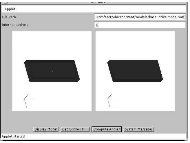
4.1 Test bed Snapshoot . . . 40
4.2 Assembly and Robot . . . 40
4.3 Assembly's parts CSG representation . . . 41
4.4 Relationships between assembly parts . . . 42
4.5 One possible assemblysequene . . . 42
4.6 Example's Constraints . . . 43
4.7 Base Part's external faes and their stabilityindexes . . . 44
4.8 Step 1: StablePositionsAnalysis . . . 45
4.9 Stayout Zones . . . 46
4.10 Two FixturingSets . . . 47
4.11 Step 2: FixturingSets Analysis . . . 48
5.1 System Snapshoot. . . 50
5.2 Loading the base part into the system. . . 56
5.3 Analyzers information . . . 57
5.4 Analyzers information . . . 58
5.5 Set of analyzers and analysis progress window fortest 1 . . . 59
5.6 Set of analyzers and analysis progress window fortest 2 . . . 59
5.8 Analysisprogress windowfor test 3 . . . 61
5.9 Analysisprogress windowfor test 4 . . . 61
5.10 System messages and History reord windows for test 3 . . . 62
Introdution
Manufaturing enterprises have always faed the hallenge of dereasing the time
in-terval between produt oneption and rst prodution. In today's world it is vital
beause nowdays enterprises had to ompete in a global market that inludes
om-panies from all around the globe [Erkes 96℄ . Moreover, almost all ompanies rely in
state-of-the-art tehnology tohandle user requests assoonas possible [Jain 01℄.
Due to historial reasons, ompanies plae design and manufaturing funtions
intodistint departments [Gupta 97℄. Therefore, the proess of bringing a produt to
market involvesseveral iterationsbetween the design andmanufaturingstas. These
iterationsare time-onsumingandthus onlyafew designalternativesan be analyzed
in order to satisfy the turn-around time onstraint, limiting the quality of the nal
produt.
It has been proved that signiant savings, both in time and money, an be
ob-tained by the abilityto make hanges during the earlyphases of design [Whitney 90℄.
This savings ould be obtained beause the ost of making design hanges when the
produt development yle has started inreases quikly with time. This fathas lead
tothedevelopmentofanumberofmethodologiesandsoftware systemstailoredtogive
designers toolsto analyze manufaturability during the design stage [Priest 01℄.
Amongallmanufaturingdomains,assemblyofeletro-mehanialdeviesisavery
important one beause a lot of the produts made world wide are eletro-mehanial
devies whih require assembly operations. Moreover, even when assembly aounts
for typially 10% to 15% of the ost of goods sold, it an aount for a great deal of
the hiddenost, around 80% inindustries like airraft [Whitney 95℄.
On the other hand, the urrent trend of onstant produt hanges makes exible
manufaturing very appealing. One way to obtain exibility is through the use of
robots, so it isvery ommontond them onmodern fatories.
Two dierent approahes ould be taken for testing the manufaturability of a
given design. One is to use metris based on dierent fators, like number of
oper-ations, omplexity of the involved operations, et. The other one is to simulate the
manufaturingproess toseeif itisfatibletobuildthedesignwithouthavingtobuild
a physialmok-up. In the ase ofroboti assembly of eletro-mehanialdevies, the
toperform the analysis [Choi 00℄.
In order to test if a given design ould be manufatured by a spei roboti ell,
designers must answer a number of questions about sequening, stability, xturing,
grasping, motion planning and tool aessibility. Typially, designers have to answer
thesequestionsbythemselveswithoutthe helpofany tool. Insome ases,the answers
an not begiven until a prototype is atually tested,with the onsequent lostof time
and money if the test isunsuessful.
Although several tools have been developed for omputing some of the answers
need by designers, they have been developed in an isolated fashion making hard the
integrationoftheirresults. Eahtoolusesitsownobjetmodels(whihhighlightsome
partiular analysis features), sets of onstraints, sale fators, and base units (inhes,
mm, et.) leadingtoinompatibilityproblems when designers havetohain them, i.e.
tousetheoutputfromonetoolastheinputforanotherone. Forinstane, ifadesigner
wants to hain Mattikalli and Khosla system [Mattikalli89℄ with Brost and Goldberg
system [Brost96℄, he/she must obtain basi geometry information from the assembly
modeldeveloped inACIS, for ommuniating both systems.
Unfortunately,these problems makedesigners would ratheranswertheir questions
empirially,one by one, and thus a system that integrates that tools is need. Suh a
systemwillrelievedesigners fromthe integrationburden allowingthemtofousonthe
reativeaspets of theirjobs.
The systems desribed in [Thomas 01℄ and [Gupta 01℄ are good examples of the
eorts made toreate automatirobot programmingenvironments and assembly
sim-ulatorsrespetively. Thereare alsoommerialsoftwaresystems forsimulatingroboti
ells, like the one depited by [Ahrens 02℄. But these systems ould not analyze all
aspets of an assembly beause they make some simpliations in order to ompute
allthesolutionswithoutuserguidane. Forinstane,the [Thomas 01℄systemassumes
the grasp positions of eah objet are pre-speied. Also, as these systems are losed
ones,itwillbehardtointegratethemwith othersowftaretoolsinordertodoabetter
analysis.
A generaltreatmentof the integration issues would lettoreatea system inwhih
assembly analysis toolsould behained together by the designer, inorderto perform
manufaturability analysis of a given assembly design for a spei roboti ell. A
system like this will help manufaturing enterprises to speed up their turn-around
times and to improve the quality of their nal produts by allowing designers analyze
several designalternativesin less time.
1.1 Problem Statement
Analysis of assembly manufaturability is not an easy task; even for the simplied
assembly and the 4 D.O.F robotshown ongure 1.1, several problems must besolved
in orderto say if the robot an assemble it:
(a) Simplied disk driveassembly
(b)SeikoRobot
Figure 1.1: Assembly and Robot
Stability: To nd aset of orientationsfor eah piee of the assembly, so they an be
positionedinthe working table withoutfallingdown.
Grasping: To nd a set of grasping points on eah piee, so they an be grasped by
the gripper withoutfallingdown.
Fixturing: To nd a set of xtures for eah piee, so they an remain on an stable
positionin the working table while the robotis making the assembly.
Motion planning: To nd free trajetories for eah assembly step, so the robot an
reah allthe piees.
Tool aesibility: Tondout ifthereisenoughroomoneahpieetoguarantee tool
aessibility.
Eah one of these problems onstitutes an ative researh area by itself, and to
automatially answer them is omputationally expensive. For instane, in order to
synthesize a grasp or axture, a set of simultaneous linear equations must be solved;
typially,there are innitesolutionsand onlysome of them must behosen.
Moreover, there are alsoseveral issuesthat must besolved in orderto integrateall
the answers. Adetailedassemblyplanisalistoftheassemblystepswithspeiations
abouthowtoplaethepiees,howtogripthemandhowtoxturethemalongwiththe
trajetories and the end-eetor hanges the robot must follow tobuild the assembly.
Togenerateafeasible detailedplan, individualanswers must beseleted insuhaway
that no one violates any of the onstraints imposed by previous solutions.
Toreateafullyautomatedassemblymanufaturabilityanalysissystemthatworks
foranykindofassemblyandanykindofrobotiellisoutofreahforatualtehnology.
Abetterideaistobuildasystemthathelpsdesignerstointegratesoftwaretools,whih
This researh desribes the design and implementation of a modular
omputer-aided framework whihenables the integration of software tools for manufaturability
analysisofrobot-madeassembliesofeletro-mehanialdeviesduringthedesignstage.
The integration of stability analysis, grasping and xturing tools was taken as a
working example;itisassumed thatafeasibleassemblysequene isgivenasinput,but
an assembly sequener ould be added as atoolif the designer wants totest dierent
sequenes.
1.2 Proposed Solution
The general problem of integrating software tools developed by dierent people had
been addressed by several works like [Yang 00, Harvey 97, Bao 96, Fromme93℄. All
of thempropose omputer frameworks that helpprofessionalprogrammersin building
new omputer systems by meansof hainingpre-existent software tools.
But designers are not professional programmers, and they do not want to build a
system; they need asystem whihletthem speifyinteratively aset of software tools
to be alled, the assembly problem to be analyzed by the tools, and the information
interhange between the tools in order to nd a set of detailed plans to build the
assembly, oratleast some advie about the probable auses of failureif noplan ould
befound. Thedesign anddevelopmentof suh asystem isthe maingoalofthis thesis.
Eah one of the speied tools will produe several alternatives, and eah one of
the alternatives must be tested to see if they are oherent with the requirements of
the other tools. Therefore, the system must beapable of integrating the information
handled byeahtool,maintainingthe ohereneoftheinformation,andautomatially
transforming the information.
Evenwhenitseemsthestatedproblemismoreatehnialproblemthanasienti
one, in orderto solve itsome importantissues were addressed:
Is there a onsistent domain ontology that ould enable the ommuniation
be-tween software toolsaimed atassembly manufaturability analysis?
How ould that ontologybe formalized?
Is thereageneralway toletdesigners speifyalls tothird-party software tools?
Isthereageneralwaytoletdesigners speifythedatainterhangebetween those
tools?
Could the toolsbeaessed via Internet?
Could the toolsbewritten inany omputer language?
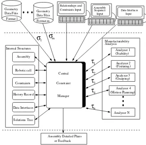
Figure1.2depitsanoverviewoftheproposedarhiteture. Asitanbeseen,itisa
modulararhiteture and onsist of three key elements: a entral onstraintmanager,
internal strutures and a set of speialized analyzers (software tools). The entral
onstraintmanagermakesrequests tothe speializedanalyzersinordertobuildatree
with all the feasible plans of assembly (solutions tree). The analyzers at as servers
apable of solving problems in grasping, stability,xturing, et. The order for alling
the analyzers and thedata ows between themand the internalstrutures isprovided
by the designer and stored in the data interfaes struture. The entral onstraint
manageralsoreordseahalltothe servers, andtheir resultsin aninternalstruture
(history reord) inorder to beapable of trae bak any oherene problem.
In a typial session the user rst feeds the system with assembly and roboti ell
desriptions. These desriptions inlude geometri data, relationships between parts,
onstraints and a feasible assembly sequene. As laimed previously, an assembly
se-quener ould be added as one of the analyzers if dierent sequenes will be tested.
Geometri dataould berestored fromles writtenin any format, as long as a
trans-formationmapping('s)between thatformatandtheinternalstruturesofthesystem
isprovided. Constraintsaredened by booleanevaluationproedures thatreturntrue
if the onstraint holds for a partiular objet orlist of objets, orfalse otherwise.
Later,theuserspeiestheorderofanalysisandthedatainterfaesbetweenthe
in-volvedproesses. Ablakboxintegrationapproahisusedallowingtheanalyzerstobe
implemented inanyomputer languageaslongasthey usethe standard input/output
system toreadvariablesandoutputresults. Sokets areusedtoommuniatewiththe
analyzers, so they ould be run in any omputer plugged to the World-Wide Web at
any loationaround the world. The entral onstraintmanager llsitsinternal
stru-tures with the information provided by the user and start to generate allthe feasible
assemblyplansthatagreewiththeseleted sequene ofassembly, usingtheonstraints
to prune the results and thusto reduethe time toompute all the feasible solutions.
Foreahstep of the sequene, the entralonstraintmanageralls the appropriate
speialized analysis proess, hek the onstraints,disardthe resultsthat violate any
onstraint, addthe validresultstothe solutions tree, andgenerate a newentry onthe
history reord to registerthe proess alled and the resultsobtained fromthat all. If
it is the ase that nofeasible planremains inthe solutions tree,the entral onstraint
manager informs the user, and allows himtosee the history reords totrae bak the
problem.
Itisworthtomention thateven whenthe proposed frameworkarhiteture
resem-bles a blakboard arhiteture [Newell 62, White 90,Nii 86, Hewett 97,Koh 00℄they
dier mainlyinthe following points:
Blakboard systems are losedsystems inthe sense thatmodyng the system to
add or replae tools requieres a programming eort. The proposed framework
is an open system beause it is designed to add or replae tools dynamially at
run-time by letting the user speify physial loation and I/O requirements of
1
σ
Format 1
Geometry
Data Files
Format m
Geometry
Data Files
σ
m
Relationships and
Constraints Input
Assembly
Sequence
Input
Data Interfaces
Input
Manufacturability
Analysis
(Stability)
Analyzer 1
(Fixturing)
Analyzer 2
(Grasping)
Analyzer 3
Analyzer 4
(Motion Planning)
Analyzer N
Assembly
Robotic cell
Constraints
Data Interfaces
Solutions Tree
Central
Constraint
Manager
τ
1
τ
2
τ
3
τ
4
τ
n
Assembly Detailed Plans
or Feedback
History Record
Internal Structures
Figure 1.2: Framework Arhiteture Overview: 's and 's represent transformation
mappings between geometry formatsand data interfaes respetively
analysis of assemblies, inludeonly high levelplanners whih an not be usedto
generate detailed assembly plans of any assembly done inany roboti ell. This
is due mainly beause to automatially handle the omputational omplexity
involved is out ofreahfor atualtehnology. The proposedframeworkdoes not
try to fully automate manufaturability analysis of assemblies, it is designed to
give designers a systemati way of searhing a verylarge solution spae, sothey
ouldtakeintoaountabiggernumberofsolutionsthanthenumberofsolutions
they atually ould handle.
1.3 Main Contributions
The majorontributions of this researh an beharaterizedas follows:
Denition and formal speiation of a entral assembly-oriented data model
wih inludes information about assemblies, roboti ells and onstraints. The
data modelis basedonaomprehensivedomainontologythat enablesthe
inter-operation of manufaturability analysis software tools by managing information
[image:21.612.145.432.97.381.2]mehanisms. Ablakboxintegrationapproahisusedallowingthesoftwaretools
to be implemented in any omputer language as long as they use the standard
input/output system to read variables and output results. Constraint
manage-mentis used asaommuniationmehanismbetween the tools. The integration
of their solutions is made by testing eah solution generated to keep oherene
with therequirementsofallthe tools. Sokets areused toommuniatewiththe
software tools,so they ouldberun inanyomputer pluggedtotheWorld-Wide
Web at any loation aroundthe world.
1.4 Organization
Chapter 2 provides bakground information, it inludes setions on Assembly Data
Modelling,AssemblyPlanning,Graspingand Fixturing,Software Integration Systems
and Blakboard Systems. Chapter 3 desribes the proposed framework. Chapter 4
presents the testbed built and aworking example. Chapter 5 provides adesriptionof
the omputer implementationof the framework anduses the previous dened working
example to test it. Finally,Chapter 6 summarizes the motivationof this researh, the
Related Work
Asstatedintheintrodution,thegoalof thisworkistobuildaomputer-aided
frame-work whih enables the integration of software tools for manufaturability analysis of
robot-made assemblies.
The software tools will answer a number of questions about sequening, stability,
xturing,grasping, motionplanningandtoolaessibility. Eahoneofthesequestions
onstitutes anativeresearharea by itself,andtoautomatiallyanswerthemis
om-putationallyexpensive. Reif showed motion planningtobe PSPACE-hard, Natarajan
and Wolterproved theassemblysequening problemwithanarbitrarynumberofparts
to be alsoPSPACE-hard, and itremainsPSPACE-hard whenthe partsare limited to
a onstant number of verties [Reif 87, Natarajan88, Wolter 88℄. For synthesizing a
grasp or a xture, a set of simultaneous linear equations must be solved. Typially,
there are innitesolutionsand onlysome of them must behosen.
The framework is designed in suh a way designers ould guide the analysis, and
eventest dierentversionsofatool. Theintegrationofstabilityanalysis,graspingand
xturing toolswas taken asa working example;it isassumed thata feasible assembly
sequene is given as input, but anassembly sequener ould be added as a tool if the
designer wants totest dierent sequenes.
Inthe followingsetions the work alreadydone inassemblydata modeling,
assem-blyplanning,graspingandxturingandsoftware integrationsystemsispresented. For
a surveyonmotionplanning, readersare referredto[Latombe93,Hwang 92℄. For
ref-erenes abouttoolaessibility,[Wilson 96℄ouldbeonsulted. Asetiononblakboard
systems isalsoinluded tomake lear the dierenes between them and the proposed
framework.
2.1 Assembly Data Modelling
Astheframeworkwillenabletheintegrationofsoftwaretoolsaimedtoassembly
manu-faturabilityanalysis,itisimportanttondoutasharedlanguage,ordomainontology,
whih lets the tools toommuniatebetween eahother.
Robotis researhers were the rst to model assemblies, and their models
[Whitney 77℄.
Later, assemblies wererepresented by aseriesofgeometri modelsforeah
individ-ualpart,andalistoftherelativepositionandorientationofeahindividualpartinthe
nalassembledonguration[Lee 85,Lin90,Minami 95℄. This approahisommonly
used by most of the works related toassemblies, and it ould be onsidered the basi
model.
In[Whitney 95℄,aomprehensivelistofaspetsthatmustbemodelforrepresenting
assemblies is given. But not an spei model is proposed beause it is laimed that
more work is needed to really understand assemblies and their models. Nevertheless,
this list isvery useful when trying to dobetter models.
Adetailedliteraturereviewabout assemblyrepresentationsispresentedbyMasle.
He onludes that the basi model remains essentially the same from one author to
another. He alsoproposes anew modelin whihthe assemblystates (or steps)are an
integral part of the produt model[Masle 99℄.
More reent works add some features tothe basi modelin order toperform
intel-ligent simulations. For instane, [Gupta 01℄ presents an assembly representation that
allows artiulation handling.
2.2 Assembly Planning
As stated in [Wolter 92℄: \An assembly planner is a program designed to generate
high-level plans for the manufature of mehanial assemblies". Assembly planners
ould be ategorized by the approah taken togenerate the plans. The most ommon
approahes are reviewed inthe next subsetions.
2.2.1 General planners
The Artiial Intelligene (AI) ommunity has always been interested inthe
develop-mentofdomain-independentplanners. The lassialAIplanningproblemisdenedin
asimpleformastheproblemofsimultaneouslyahievingatthenaltimeseveralgoals
alled \subgoals". A planner determines the order whih makes the goal ahievable.
In some ases the goal state an be ahieved if the subgoalsare ahieved in a ertain
order (linear planning problem). However, in other ases even thought the goal state
isvalidand ahievable thereis noorderingonthe onjuted subgoalsthat an ahieve
the goal state (non-linear planning problem). Theoretially, the underlying planning
method inthese systems isdedution.
STRIPS was one of the rst pratial planners wih fous in the onjutive goal
problem [Fikes 71℄. It was based on the linearity assumption and ould solve only
problems where the onjution of several subgoals ould be ahieved by ordering the
subgoal ahievement proesses. NOAH and SIPE are also representative examples of
thesedomain-independentplanners [Saerdoti 77,Wilkins 84℄. In STRIPSandNOAH
Buildisanad-hoplannerforbuildingspeiedstruturesoutofsimpletoybloks,
the planning is done in a modeled 3D-spae in whih bloks of various shapes and
sizes an be represented in any orientation and loation; it inorporates geometrial
tests for inter-objet ontat and ollision,and for stability involving fritional fores
[Fahlman 74℄.
Another AI approah is presented by Bakstrom; he uses rst order prediate
al-ulus for geometri reasoning about assembly proesses. His work is restrited to a
2D-world and no planner is presented, just an algorithm for verifying assembly steps
[Bakstrom 87℄.
Unfortunately, this kind of planners do not reason about geometri onstraints in
the way needed by anassemblyplannerbeausealmostallmakeuse ofaveryabstrat
geometri desription of the objetsand their relationsexpressed inlogial notation.
2.2.2 Sequeners
Assemblyplanningmayalsobeviewedasageneralmotionplanningproblem,butthat
makes extremly hard to handle it [Latombe 93℄. This fat has lead to a simpler
sub-problem denition known as assembly sequene planning in whih only the geometri
onstrains arisingfromtheassemblyitselfare onsideredassumingthattheparts
om-posing the assembly are free-ying objets, i.e. the manipulation system (e.g. robots)
is ignored.
Sequene editors
The early assembly sequeners were mainly sequene editors in whih geometri
rea-soning was supplied by a human who answers questions asked by the systems, whih
in turn generate the assembly sequene from the answers.
Thesystem developed by Bourjaultrepresentsthe rst step towards anautomated
assembly planner. That system asks a human expert arefully onstruted yes-no
questions, and the preedene relationships between onnetions or between logial
ombinationsofonnetionsareinferredfromtheanswers[Bourjault 84℄. DeFazioand
Withney present an improvement on the number of questions asked to the user. For
simple ases, these approahes take advantage of the expert intuitive understanding
of parts relations and feasibility of operations. Unfortunately, the orretness and
ompleteness of the algorithms used in both systems have not been proved and it
is neesary to have those proofs in order to guarantee that the resulting preedene
relations are satised by all the feasible assembly sequenes and only by the feasible
ones; besides,forlargeassemblies,itisverydiÆultforahumanexpert togiveorret
answers [De Fazio 87℄ .
Generate-and-test sequeners
questionstohektheirfeasibility,andsomegeometrireasoningmodulesforanswering
these questions.
Geometri omputations are repeated several times making relatively inneient
this approah tothe pointthat itis appliable onlyto assemblies with few parts.
Homem de Mello and Sanderson present a orret and omplete algorithmfor the
generationof mehanial assemblysequenes. They transformtheproblemof
generat-ing assembly sequenes into the problem of generating disassembly ones. Assemblies
are represented through arelational modelthat inludesparts, ontats, attahments
and a set of relationships between them [Homem de Mello88℄ . Galloand Pallottino
presents omputationallyeÆient hyper-graph algorithmsto solve the assembly
prob-lemas dened by Homemde Melloand Sanderson [Gallo 92℄.
Frommherz and Hornberger also use the disassembly tehnique, but they use only
geometrial informationabout eah part of the assembly as input. Their outputis in
the form of preedene graphs[Frommherz 88℄.
Mattikalli and Khosla developed a system apable of determining assembly
se-quenesinvolvingrotationalandtranslationalonstraints. They userelativelydetailed
3D models as input [Mattikalli89℄.
Santohi and Dini desribe FLAPS (Flexible Assembly Planning System), a
om-pletesystem forthe planningofassemblyoperations. A ompromisebetween the fully
automated and the interative approah is used; they ask the user information about
preedenerules,aessibilityonstraintsandelementsthatannotbedisassembledby
simple translation. The system ismade of four modules,only the rst one isreported
as fully implemented: sequene generation, assembly operation planning, seletion of
the best assembly sequene, and o-lineprogrammingof mahines [Santohi 92℄.
2.2.3 Other approahes
Wilson and Latombe redued the omplexity of generating assembly algortihms for
3D models to polynomial bonds through the use of non-diretional bloking graphs
(NDBG), whihdesribes the potentialinterations amongparts in polynomialspae.
Their onstrution derives from the observation that innite families of motions an
be partitioned into nite olletions of subsets suh that the interferenes among the
parts are onstant over every subset. One omputed, the NDBG an be exploited
for a variety of purposes, inludingthe polynomial generation of assembly algorithms
[Wilson 94℄.
Mostoftheaboveplanners haveproblems whendealingwith realworldassemblies,
Chakrabarty and Wolter propose a hierarhial approah to lessen the ombinatorial
problems in realisti assemblies. They view an assembly as a hierarhy of standard
strutures and merge partial plans for these strutures to derive a plan for the whole
assembly. Their system take advantage of the fatthat ertain typial ways in whih
setsofpartsareombinedreurveryoften,notonlyinagivenassemblybutindierent
assemblies aswell. Theombinatorialproblems arelessened beausetheplans for
reasoning rst about geometri properties and then, about non-geometri onstraints [Lin 93℄.
Kaufman et. al have developed another omplete system, Arhimedes 2. They
relyonuserinputinsteadofusing sophistiatedfeature-reognitionsoftware,and have
implemented a fastollision detetion algorithm. Thisalgorithmuses agraphi
work-station hardware Z buer to quikly nd ollisions between omplex faeted models.
Their system haveomputed sequenes for assemblies from both industryand
govern-ment [Kaufman96℄.
Other approahes taken to solve the assembly planning problem inlude the use
of Petri Nets [Zhang89, Astuti 94, Caselli 95℄, ase-based reasoning [Pu 92℄, state
matrix representation [Noorhosseini 95℄, otree representation [Dini95℄, and geneti
algorithms[Bonneville 95℄.
AnewversionofArhimedessystem, Arhimedes4isdesribed in[Calton99℄. The
newsystemtakesasinputaCADmodel,automatiallyomputespart-to-partontats
and ollision-free insertion motions using the NDBG approah, and the fast ollision
detetion algorithmto generate feasible sequenes that are ranked by a user-speied
quality metri(speiedintermsofostsfor standardassemblyproesssteps likepart
insertion, fastening,et.). Italsohasaninterativeuserinterfaewhihletstheuserto
systematially explore the spae of feasible sequenes. Then the user ould add more
onstraints, like requering ertain parts to be assembled rst and ask the system to
generate again the feasible sequenes. Five modules were added to handle ergonomi
and ostanalysisanddenitionoftool,graspingandxturingonstraints. Thesystem
hasbeentestedover100assembliesandtheminimumandmaximumreportedplanning
timesare4seondsand6hoursrespetively. Also,usershavereporteda75%redution
in time shedules, and 25% redution inprototyping fabriation.
2.3 Grasping and Fixturing
Grasping and xturing are losely related. Both of them pursue the same goal: tox
an objet kinematiallyby meansof asuitable set of ontats. Thus, it is logialthat
researh in one area benets the other and vie versa.
Formally, the ation of grasping an objet an be dened as the plaement of the
gripper relative to the objet, and it is haraterized by a set of ontats alled a
grasp. Grasp planningonsists in hoosing the loation,the type (pointwith frition,
soft nger, et.) and appliedfores and torques.
The planning must be done in suh a way there is a ollision free trajetory to
reah every ontat, the objets are seurely grasped and holded, the task ould be
performed,andthereisawaytodroptheobjetinaknownonguration. Dealingwith
all these onditions is intratable, so grasp planning is usually split into overlapping
subproblems.
Two importantoneptsinthe areaarethose of\formlosure"and\fore losure"
A \fore losure" grasp is a grasp where the maintenane of the body's equilibrium
requires the appliation of anexternally applied wrenh [Trinkle92℄.
An extensive survey onxturingand graspingan befound in[Pertin-Troaz 89℄.
A review of gripperdesigns, ontrolmethodsand grasp ongurations is presented by
[Boubekri 02℄.
Reuleauxwasthersttoworkthroughtheunderstandingofgraspingandxturing.
On his work he showed that four higher-pair ontats were requiered to prevent all
motion fora rigid laminarestrited towork in aplane [Reuleaux 76℄.
Somo alsowas apioneeronthis area, and he stablished that aminimumof seven
pointontatsareneessary forformlosureofanarbitrary3Drigidbody[Somo 00℄.
The rst works on human grasping are due to Napier. In those works, human
grasping is studied from anatomial and funtional points of view, and two patterns
forprehensilemovementsareproposed: the powergraspandthe preisiongrasp. Also,
one non-prehensile postureis dened: the hook grasp [Napier56, Napier 62℄.
Napier studies stimulated the further development of dextrous robot hands, like
the tri-ngered hand with adjustable rigidity one developed by Hanafusa and Asada.
They alsodeveloped anheuristiforobtainingastablegrasp fromasensoryprolefor
theirhand,and basedthatheuristionthesearhforaloalminimumofthe potential
funtion with the enter of the hand near the entroid of the prole [Hanafusa 77a,
Hanafusa 77b℄.
Lakshminarayanawasthersttodesribeanapproahtosynthesizingform-losure
grasps of 3D fritionless objets; he also showed that seven ngers are neessary to
ahieve fore-losure of a 3D objet [Lakshminarayana 78℄.
Abel,HolzmannandMCarthydetailanalgorithmtondaurveofpossiblegrasps
fromasetofequilibriumequationsparametrizedbythemagnitudoftheappliedfores;
theyalsointroduedtheoneptofinipientrigidbodyslipandshowedhowtoompute
the frition fores assoiated with a grasping[Abel 85, Holzmann 85℄.
Mason and Salisburygave onditionsforomplete restraintof anobjetby agrasp
in terms of internal fore. Their work was used for the design of hands that grasp
seurely and for generalized graspingwhen the motion of the objet to manipulate is
not ompletely onstrainedby the gripper, partiularlywhen pushing[Mason 85℄.
Cutkosky developed a proedure for analyzingthe grasp properties of stiness and
resistane to stipping and introdue the onept of innitesimal stability in order to
ompare grasps [Cutkoski 85℄.
NguyenusedReuleauxideastodevelopalgorithmstosynthesizeform-losuregrasps
of given rigid laminaand 3D objets. Theseworks alsopresentbinary tests indiating
the existene ornon existeneof form losure[Nguyen 86℄.
Ji and Roth gave onditions for equilibrium and fore losure in the three nger
ase [Ji87℄. Nguyen presented a geometri test for two-nger fore-losure grasps on
both polygonal and polyhedralobjets [Nguyen 88℄.
Markenso, Ni and Papadimitriou proved that any non exeptional fritionless
objet anbegrasped informlosurewith onlyseven ontat points[Markenso 90℄.
Lately, systems for omputer-aided planning and analysis of xture set up, and
omputer-aided xture design veriation are disussed in [Shirinzadeh 02, Kang 02℄
respetively.
Also a new tehnique for workpiee retention during mahine proessing based on
eletrorheologial uids ispresented by [Monkman01℄.
2.4 Software Integration Systems
In the eld of Software Engineering, reuse of ode has been always a goal to improve
system prodution. As early as the eighties, work had been reported for setting the
harateristisof integrable software tools[Nejmeh 89℄.
Sine then a number of software integration frameworks oer a reusable faility
for the integration of software tools; typially they provide at least a ommuniation
mehanism,adatastorageandaontrolfailitytobuildnewsystemsbasedonalready
devlopedones. Asurveyaboutthiskindofenvironmentsouldbefoundin[Harvey 93℄.
Among others, the works of [Yang 00, Harvey 97, Bao 96, Fromme 93℄ are
repre-sentativesof the urrenttrends inthearea. Allof themproposeomputer frameworks
that help professional programmers in building new omputer systems by means of
hainingpre-existent software tools.
But designers are not professional programmers, and they do not want to build a
system; they need a systemwhihletthem speify interativelyaset of software tools
to be alled, the assembly problem to be analyzed by the tools, and the information
interhange between the tools in order to nd a set of detailed plans to build the
assembly, orat least someadvie about the probable auses offailureif no plan ould
befound.
The work desribed in[Weatherill99℄allows the integration of arbitraryomputer
appliation software into an environment to provide a multi-disiplinary engineering
analysis apability within one unied omputational framework. Unfortunately, it
works only forunstrutured gridappliations and itdoesnot havethe failityto
inte-grate several answers.
Otherintegrationeortshad fousedintodevelopingsystemsthat ouldplan,
eval-uate and exeute programs for industrial robots. In order to do that, the systems
must synthesize a robot spei program from a sequene of tasks, must deide how
to grasp and xture the parts, and whih are the robotmotions needed toaomplish
the task athand. Thisresearh area isknown asTask-Level RobotProgramming.The
deisions took by these systems are interdependent and propagate aross eah other.
For instane, the hoie of a grasping onguration determines what motions of the
robotare requiredtopositionthe part. So, onstraints mustbemonitoredarefullyto
ensure that the seleted optionssatisfy all the requirements.
The rst attempt to develop suh a system was done by [Ernst 61℄. Sine then,
a number of systems and languages have been proposed: the Stanford Hand-Eye
[Lozano-Perez 85℄,theCornellRobotSystem[Campbell85℄,Handey[Lozano-Perez 89℄,
SPAR [Huthinson 90℄and IRAS [Tung 94℄ amongothers.
Most of these systems were not implemented at all, or were ustom designed and
tailored to very spei tasks in order to deal with the omputational omplexity
involved when trying tointegrateall the omputationsneedfor generatinga omplete
system. Forinstane,the CornellRobotSystem,Handey,SPARandIRAS arelimited
primarily topik-and-plae operations.
TheArhimedessystems[Kaufman96,Calton99℄gobeyondpik-and-plae
assem-bly,but they produe ode for a spei work-ell.
Carrikerworkalsogoesbeyondpik-and-plaeassemblyby theuse ofanextensible
frameworkof modular planners, modeling systems and software tools. His system an
generate ode for dierent work-ells, but his grasping and xturing algorithms are
restrited to spei xtures and grippers. Also, it is not lear from his work how to
replae one planner by a better one, or how to add new planners in order to handle
dierent kindsof tools. He also does not take into aount mehanisms for providing
feedbak tothe designers [Carriker 95℄.
Thomas system is useful for diferent roboti ells, beause it uses a arefully
de-signed library of skill primitives, but itassumes the grasp positions of eahobjet are
pre-speied [Thomas 01℄.
2.5 Blakboard systems
Blakboard systems use a group of ooperating knowledge-based systems (knowledge
soures)whihommuniatewitheahotherbysharinginformationonaommondata
struture alled a blakboard. Newell oined the term blakboard by analogy with a
physialblakboardinwhihooperatingworkers ouldaddordeleteinformationwhile
solving a problem[Newell 62℄. The blakboard must be leaned from time to time to
prevent luttering. They an be applied to various types of problems, partiularly
those where sub-problems require nospei order of solution. They are alsosuitable
for problems where multiple lines of reasoning exist[White 90℄.
The ontrol strategy used by blakboard systems is termed opportunisti beause
eah knowledge system monitors the blakboard and ativates itself based on the
so-lutionstate represented by the blakboard. Formonitoring theblakboard,knowledge
systems must see everything onthe blakboard atall times and must write their
on-lusions withoutgettingin the way of other knowledge systems [Nii86℄.
The basiexeutionyle ofany blakboardsystem has threemainphases: agenda
maintenane,sheduling,andknowledgesoureexeution. Tomaintaintheagenda
up-to-datetwolistsarekept,oneisthetriggeredagendawhihliststheknowledgesoures
alreadytriggeredbysomeevents,theotheroneistheexeutableagendawhihliststhe
knowledge soures ready for exeution. The sheduling is done by seleting the best
knowledge soure available for exeution in eah yle, based on ontrol knowledge.
onditions determinewhetherthe knowledgesoureisexeutable, obviationonditions
indiate whih knowledge soures must be removed from the agenda and be
perma-nently disarded, ontrol knowledge let the system to rank the knowledge soures in
the exeutionagenda, and selet the best one of them [Hewett 97℄.
Trigger onditions, preonditions for exeution, obviation onditions and ontrol
knowledge are appliation-spei and must be enoded by someone, usually a
sys-tem integrator with some experiene in the appliation and in knowledge modeling
[Lander 96℄.
Commerialavailable high-performane blakboardtoolkits,suh asGBBorKPM
from Knwoledge Tehnologies International, let system integrators to develop
blak-board systems whih ombine a number of analysis tools. However, the developed
systems are losed systems beause they are not designed for hanging dynamially
the set of knowledgesoures whihare involved; toadd or replaeany tool,the whole
environment must be at least reompiled. Also, any tool that was not speially
developed as part of the system must be wrapped in an enapsulation shell in order
to anhor it into the system's infraestruture [Lander96℄. In that sense, blakboard
systems are similarto generalsoftware integration systems disused earlier.
Anumberof blakboardsystems had been developedtoaidinthe areaofrobotis.
Mainly, they had been used to implement ontrol approahes for oordinating
au-tonomous robots[Lisano 95, Oello92, Harmon 86,Bzzyky 01℄ orto implement
in-telligentontrolstrategies for a single robot[Ananthanarayanan 92℄.
Additionally, asystem for exible assembly ooperative planningwas proposed by
[Lee 90℄. This system oordinate a number of intelligent agents aimed to generate
assemblyplans. Ituses asinputanobjetmodelwhihintegrates basi informationof
parts and liasons between the parts. It is similar to [Chakrabarty 94℄ beause it also
proposes ahierarhial approahtoexploit paralellism. Anassemblyost isomputed
in order toselet assemblies with minimalost.
In general terms, blakboard systems had been eetive for high level planning,
like proess planning, supply hain planning and prodution shedule [Laliberty 96,
Sadeh 99℄. Also,they work wellinevent-data proessingofexperimentalsetupswhih
are outside ofhuman ontroland whih produesdata atunknown timepointsand in
unknown numbers [Koh 00℄.
High level planning is not apable of reasoning about geometri onstraints, in
the way needed by manufaturabilityanalysis ofassemblies, beause most of the time
it uses abstrat geometri desriptions of the assembly and the roboti ell. Even
when detailed geometri desriptions are used in some points of the planning, to
au-tomatiallyhandlethe omputationalomplexity involved whentrying touse detailed
geometri desriptions all the time isout of reah for atual tehnology. On the other
hand, manufatuarbilityanalysis ofassemblies involvesfairlystraighforward sequenes
of ativities whihare appliedto aomplish spei goals, and this kind of sequenes
are diÆulttostruture appropriately with opportunisti ontrol.
Theframeworkproposed by thisthesishas threekeyelements: aentralonstraint
systems and some ontrolstrategy for oordinating those systems.
Nevertheless, the proposed framework diers from blakboard systems in the
fol-lowing points:
Blakboardsystems are losed systemsin the sensethat modyng the systemto
add or replae tools requieres a programming eort. The proposed framework
is an open system beause it is designed toadd or replae tools dynamially at
run-time by letting the user speify physial loation and I/O requirements of
eahtoolused.
Blakboard systems developed until now, in areas related to manufatuarbility
analysis of assemblies, inludeonly high levelplanners whih an not be usedto
generate detailed assembly plans of any assembly done inany roboti ell. This
is due mainly beause to automatially handle the omputational omplexity
involved is out ofreahfor atualtehnology. The proposedframeworkdoes not
try to fully automate manufaturability analysis of assemblies, it is designed to
give the designer asystemati way of searhing a very large solution spae.
2.6 Summary
This hapter has presented the state of the art in the areas related to this researh:
assembly data modeling, assembly planning, graspingand xturing and software
inte-gration systems. The review of previous work for eah area was done fousing in the
aspetsthat needtobesolvedinordertobuild theframeworkproposed bythis thesis.
From this review it follows that:
There isnoformal assembly data modelthat inludesinformationabout
assem-blies, roboti ells and onstraints. There is a lak of a shared language for
ommuniating toolsfor assembly manufaturability analysis.
Atual planningsystems were developed as losedsystems so itisno possible to
add third-party software tothem for doing better analysis.
Even when general software integration frameworks let make new systems by
mixing third-party software, they are too general to be used by designers and
they are not apableof hanginginterativelythe mixed software atrun time.
Task-levelrobotprogrammingsystemsalsohadbeendevelopedaslosedsystems.
Asetiononblakboardsystemswasalsoinludedtomakelearthedierenesbetween
them andthe proposed framework. Mainly, the framework isdierentbeause itisan
open system whih ould integrate third-party software, and does not try to fully
Framework
As statedearlier,the maingoalofthis researhis toshow thatitisfeasible todevelop
a modular omputer-aided framework whih enables the integration of software tools
for manufaturability analysis of robot-madeassemblies of eletro-mehanial devies
during the design stage.
Aseahone of thespeiedtoolswillprodueseveral alternatives, andeahone of
the alternativesmust betestedtosee ifthey are oherentwiththe requirementsofthe
othertools,thesystemmustbeapableofintegratingtheinformationhandledby eah
tool,maintainingtheohereneoftheinformation,andautomatiallytransformingthe
information.
To gure out some of the harateristis of suh an integrative system, a testbed
was developed to emulate the atual problems designers must fae when they deide
to use the analyisis toolsthey had at hand. The testbed isdesribed in next hapter.
Even whenitseemsthestatedproblemismoreatehnialproblemthanasienti
one, in order tosolveit some interesting issues were addressed:
Is there a onsistent domain ontology that ould enable the ommuniation
be-tween software toolsaimed at assembly manufaturabilityanalysis?
Howould that ontologybeformalized?
Is therea generalway toletdesigners speify alls tothird-party software tools?
Isthereageneralway toletdesignersspeifythe datainterhangebetweenthose
tools?
Could the tools be aessed via Internet?
Could the tools be writtenin any omputer language?
Is there a way to letdesigners prunethe solutionspae?
Could the geometry data be represented inany format?
Inthefollowingsetionsthedesriptionoftheframeworkproposed bythisresearh
3.1 Framework overview
Althoughthereisnouniversal denitionofthe termmanufaturability,itisaommon
plaetounderstanditasthe referenetothedesignharateristiswhihindiatehow
diÆultor easy the designis from manufaturing perspetive[Gupta 97℄.
Instead of proposing someindex of manufaturability, aonstrutiveapproahwas
used tosolvethis problem,i.efeasibleplansmust befound inordertoverifyif agiven
assembly design is manufaturable by a given roboti ell. If no plan ould be found,
some advie about the probable auses of failuremust begiven.
Figure 3.1 depits an overview of the proposed framework. As it an be seen, it
has a modular arhiteture and onsist of three key elements: a entral onstraint
manager, internal strutures and a set of speialized analyzers (software tools). The
entral onstraint manager makes requests to the speialized analyzers in order to
build a tree with allthe feasible plans of assembly (solutions tree). The analyzers at
as servers apable of solving problems in grasping, stability, xturing, et. The order
for alling the analyzersand the data ows between them and the internal strutures
is provided by the designer and stored in the data interfaes struture. The entral
onstraintmanageralsoreordseahalltothe servers, andtheirresultsinaninternal
struture (history reord) inorder tobeapable of trae bak any oherene problem.
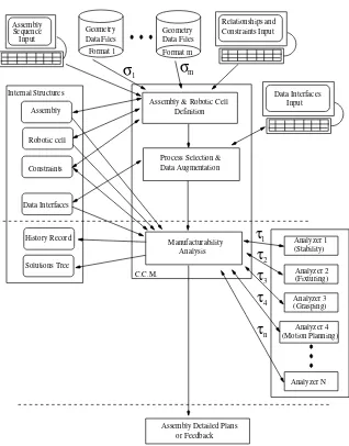
As shown in gure 3.2, in a typialsession the user rst feeds the system with
as-sembly and roboti elldesriptions. These desriptions inlude geometri data,
rela-tionshipsbetween parts,onstraintsandanassemblysequene. Aslaimedpreviously,
anassemblysequenerouldbeaddedasoneoftheanalyzersifdierentsequenes will
be tested. Geometri data ould be restored from les written in any format, as long
as a transformation mapping ( 's) between that format and the internal strutures
of the system is provided. Constraints are dened by boolean evaluation proedures
thatreturntrue ifthe onstraintholds forapartiularobjetorlistofobjets, orfalse
otherwise.
Later,theuserspeiestheorderofanalysisandthedatainterfaesbetween the
in-volvedproesses. Ablakboxintegrationapproahisusedallowingtheanalyzerstobe
implemented inany omputer languageaslong asthey use the standard input/output
systemtoreadvariablesandoutputresults. Sokets areusedtoommuniatewiththe
analyzers, so they ould be run in any omputer plugged to the World-Wide Web at
any loationaround the world. The entralonstraint managerlls itsinternal
stru-tures with the informationprovided by the user and start togenerate all the feasible
plansthat agreewiththe seleted sequene ofassembly, usingtheonstraintstoprune
the results and thus toredue the time to ompute allthe feasible solutions.
Foreah step ofthe sequene, the entralonstraint manageralls the appropriate
speialized analysis proess, heks the onstraints, disards the results that violate
any onstraint, add the valid results to the solutions tree, and generate a new entry
on the history reord to register the proess alled and the results obtained from that
all. Whenever no feasible plan remains in the solutions tree, the entral onstraint
1
σ
Format 1
Geometry
Data Files
Format m
Geometry
Data Files
σ
m
Relationships and
Constraints Input
Assembly
Sequence
Input
Data Interfaces
Input
Manufacturability
Analysis
(Stability)
Analyzer 1
(Fixturing)
Analyzer 2
(Grasping)
Analyzer 3
Analyzer 4
(Motion Planning)
Analyzer N
Assembly
Robotic cell
Constraints
Data Interfaces
Solutions Tree
Central
Constraint
Manager
τ
1
τ
2
τ
3
τ
4
τ
n
Assembly Detailed Plans
or Feedback
History Record
Internal Structures
Figure 3.1: Framework Arhiteture Overview: 'sand 's represent transformation
[image:36.612.159.476.235.555.2]Assembly & Robotic Cell
Definition
1
σ
σ
m
Assembly
Internal Structures
Solutions Tree
History Record
Data Interfaces
Robotic cell
Constraints
Process Selection &
Data Augmentation
Data Interfaces
Input
Manufacturability
Analysis
(Stability)
Analyzer 1
(Fixturing)
Analyzer 2
(Grasping)
Analyzer 3
Analyzer 4
(Motion Planning)
Analyzer N
Assembly Detailed Plans
or Feedback
1
τ
τ
2
τ
3
τ
4
τ
n
Relationships and
Constraints Input
Format 1
Geometry
Data Files
Format m
Geometry
Data Files
Assembly
Sequence
Input
C.C.M.
Figure 3.2: Framework arhiteture exeution ow for a typial session: 's and
'srepresent transformationmappings between geometry formatsand data interfaes
[image:37.612.135.453.182.588.2]Sequence
Step
Part
Id
Step
Id
Part
Mating
Part
Mating
Relation
Fixtured
Part
Id
Geometrical Descr.
Kind
Info
Volume
Gravity
Center
of
Reference Frame
Reference Frame
Assembly
Figure3.3: Assembly Objet Representation
3.2 Internal Strutures
The proposed framework must be apable of integrating the information handled by
eahtool,maintainingthe oherene ofthe information,and automatially
transform-ing the information.
Therefore,itisneessary tosetasharedlanguage,ordomainontology,
omprehen-sive enoughto handle informationfor haining proesses, storingsolutions and giving
feedbakto theuser. A omprehensiveontologyinludesallthe basionepts needed
to fully desribe the domain.
The internal strutures depited in gure 3.1 let the Central Constraint Manager
managethe domainontologyproposed by thiswork. Aentralassembly-orienteddata
modelisinludedinsidetheontology,anditisstoredin3dierentstrutures: assembly,
roboti ell, and onstraints.
The informationneeded to give feedbak tothe user isstored inthe history reord
internal struture, the information needed to use the output from one proess as the
inputfor anotherone isstoredinthedatainterfaesinternalstruture, andthe results
of the analysis are stored inthe solutions tree internalstruture.
Asstated in[Woodok 96℄, the ornerstoneof any formalsoftware development is
the onstrutionof a lear speiation. The domain ontologyis speied using the Z
notation in the following setions. Fora omplete desription of Z readers are refered
to [Woodok 96℄.
All the referene frames mentioned below are represented by 4
4-homogeneous-transform matries[Shilling 90℄.
3.2.1 Assembly
An assembly data model would ontain all the information any proess would want
to know about an assembly, but suh a database might be unmanageably large or
hard to navigate. Thus, to represent anassembly, a subset of the aspets of assembly
outlined by Whitney as neessary or useful in an assembly-oriented database were
Figure3.4: BoundaryRepresentation (BREP):asolid isdesribed asalistof verties,
edgesandfaes. Eahvertexisdenedbythreeoordinates (x,y,z), anedgeisdened
by two verties, and a fae is dened by a listof edges. Forinstane V1 is dened by
(X1,Y1,Z1), E1is dened by (V1,V6) and f1 is dened by (V1,V2,V8,V7).
sequene steps, and a referene frameto loate the assembly onthe global oordinate
system. The assembly referene frame allows the plaement of the assembly relative
tothe globaloordinate system.
Foreahpartthe usermust provideanidentier(Id),ageometridesriptionanda
refereneframe toloate the part onthe loaloordinatesystem. Eahpart referene
frameallows the plaementof parts relative tothe assembly oordinatesystem.
Thegeometridesriptionsarerestoredfromgeometrydatales. Thedatalesan
bewritteninanyformat,aslongasatransformationproedureisprovided totranslate
ittoboundaryrepresentation(BRep). BRepisarepresentation shematausedinsolid
modeling whih desribes the oriented surfae of a solid as adata struture omposed
of verties,edges, and faes [Homann 89℄, asseen ingure 3.4.
Otherwise, the geometri desriptions must be given in terms of CSG ommands
through the use of the Vantage Modeling System [Balakumar 91℄. CSG stands for
\Construtive Solid Geometry" and is another way to represent solids. Within this
approah,solidsarerepresentedasasetofBooleanexpresionsofprimitivesolidobjets,
of a simplerstruture [Homann 89℄, as seen in gure3.5.
The Central Constraint Manager asks the speialized analyzers to ompute other
geometri desriptions (for example, BRep information) and attributes (volume and
enter of gravity) asthey are required.
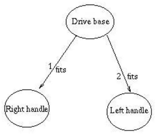
Figure3.6desribesthe sequene ofassembly asanayli direted graphinwhih
the vertexes represent the parts, andthe labeleddireted ars between vertexes dene
the order of assemblyand the relationships between parts.
The work of Anantha, Kramer and Crawford is used to desribe the relationships
between parts, i.e. all the relationships between parts are modeled through the ts,
Figure3.5: CSGrepresentation: Asolidisdesribedbybooleanexpresions ofprimitive
solid objets. The L-shaped solid is represented as a unionof the two boxes.
Figure 3.6: Assembly sequene representation, vertexes are parts, labeled ars dene
[image:40.612.175.352.121.321.2] [image:40.612.192.443.446.666.2]000000
000000
111111
111111
000000
000000
000000
111111
111111
111111
Fits
(a)Fits00000000000
00000000000
00000000000
00000000000
00000000000
00000000000
00000000000
00000000000
00000000000
11111111111
11111111111
11111111111
11111111111
11111111111
11111111111
11111111111
11111111111
11111111111
0000000000
0000000000
0000000000
0000000000
0000000000
0000000000
0000000000
0000000000
0000000000
1111111111
1111111111
1111111111
1111111111
1111111111
1111111111
1111111111
1111111111
1111111111
Parallel
(b)Parallel0000000000
0000000000
1111111111
1111111111
Against
() AgainstFigure3.7: Mating onditions
in appendix A. In the following paragraphs the most important speiations are
presented in reverse order, so readers ould go from a general speiation to a more
detailedone.
An Assembly is dened by a list of sequene steps, a list of parts and a referene
frame. The listof sequene steps must not be empty, and at least 2 parts are needed
toform anassembly.
Assembly
Sequene :iseqSequeneStep
Parts :iseqPARTID
RF :REFERENCEFRAMEID
Sequene 6=hi
#Parts 2
Asequenestepisdened byanId,abasepart, amatingpart,themating
relation-ships between the base part and the mating part, a xtured part, the xture in use,
and the end eetor in use. The xtured part ould be the base part or the mating
partand theremust beatleast onematingrelationshipbetween thebase partand the
mating part.
SequeneStep
Id :SEQUENCESTEPID
BasePart :PARTID
MatingPart :PARTID
MatingRel :iseqMatingData
FixturedPart :PARTID
FixtureInUse :FIXTUREID
EndEetorInUse :ENDEFFECTORID
FixturedPart =BasePart _MatingPart
#MatingRel 1
A Part is dened by an Id, a list of geometry desriptions, a volume, a enter of
gravity and a refereneframe. The listof geometrydesriptions must not be empty.
Part
Id :PARTID
GD :iseqGEOMETRYDESCRIPTIONID
Vol :VOLUMEID
CenterofGravity :CENTERID
RF :REFERENCEFRAMEID
GD 6=hi
A Geometry Desriptionof a 3D-objet is dened by an Id, akind and data.
GeometryDesription
Id :GEOMETRYDESCRIPTIONID
Kind :KindsOfGeometry
Info :Data
Kind =Info:Kind
Datato dene a3D-objet ouldbeBoundary Dataor PropietaryData.
Data =b BoundaryData _PropietaryData
A referene frameisdened by a 44-homogeneous-transformmatrix.
RefereneFrame
Id :REFERENCEFRAMEID
XRotation :R R R
YRotation :R R R
ZRotation :R R R
Position :R R R
Perspetive :R R R
Sale:R
3.2.2 Roboti Cell
The objet representation of the roboti ell is depited in gure 3.8. A roboti ell
desription enapsulates the information of all its omponents: a robot, xtures and
end-eetors (tools and grippers).
As for the assembly, the geometrial desription of the robot, xtures and
end-eetors an be restored from geometri data les and the referene frames will be