ADVANCES IN AUDIO SIGNAL ENHANCEMENT AND STRINGED
INSTRUMENT EMULATION USING REAL-TIME DSP
PACS Reference: 43.75.De
Gaydecki Patrick1; Woodhouse Jim2; Cross Ian3
1
DIAS, UMIST, PO Box 88, Manchester M60 1QD, UK Tel: 44 (0) 161 200 4906
Fax: 44 (0) 161 200 4911
E-mail: [email protected]
2
Department of Engineering, University of Cambridge, Cambridge, CB2 1PZ, UK Tel: 44 (0) 1223 332642
Fax: 44 (0) 1223 332662 E-mail: [email protected]
3
Faculty of Music, University of Cambridge, Cambridge, CB3 9DP, UK Tel: 44 (0) 1223 335185
Fax: 44 (0) 1223 335067 E-mail: [email protected]
ABSTRACT
A new generation of digital signal processors combined with flexible real-time software is facilitating progress in acoustic and musical technologies in several key areas, three of which are considered here: first, how musical or audio-bandwidth signals may be modified, enhanced or deliberately degraded; second, how sounds produced by musical instruments can be decomposed with extreme precision into distinct frequency and phase groupings, fostering a greater understanding of the psychoacoustic parameters that determine how we perceive factors such as musical quality; finally, how the frequency responses of stringed instruments may be exploited, by employing these fast real-time processors in the development of new "digital-acoustic" instruments with exceptional acoustic fidelity. Advances in these subjects have occurred predominantly as a result of real-time digital signal processing (DSP). A simple, linear, arbitrary frequency and phase response filter, with a real-time spectral resolution of over one part in one thousand is impossible to design using analogue components, yet forms the basis of the instrument body impulse response. Although it might be argued that real-time DSP fundamentally does not alter our understanding of the physical principles underpinning the production of sound from acoustic instruments, it is also the case that in recent times, the quantitative improvement in speed of these devices has made possible the execution of tests previously considered "thought experiments". In turn, these may yet provide new and qualitatively different insights into psychoacoustic mechanisms.
INTRODUCTION
Filters constructed using DSP technology offer many advantages over traditional analogue methods. They are inherently flexible, since changing the characteristics of the filter merely involves changing the program code or filter coefficients; with an analogue filter, physical reconstruction is required. Furthermore, they are immune to the effects of ageing and environmental conditions, since the filtering process is dependent on numerical calculations, not mechanical characteristics of the components. This makes them particularly suited for very low frequency signals. For the same reason, the performance of digital filters can be specified with extreme precision, in contrast to analogue filters where a 5% figure is considered excellent.
BASIC DSP FILTER THEORY
The (linear) process of filtering in time t is encapsulated in the convolution integral
τ
τ
τ
x
t
d
h
t
y
(
)
=
∫
∞(
)
(
−
)
∞
− (1)
where y(t) is the output (filtered) signal, x(t) is the incoming signal, τ is the time-shift operator
and h(τ) is the impulse response of the filter. In discrete space, this equation may be
implemented using either an FIR or IIR solution. In the former case, the infinite response is truncated, which yields an expression of the form:
∑
=−
=
M kk
n
x
k
h
n
y
0]
[
]
[
]
[
(2)with the z-transform of the impulse response, ie the transfer function H(z), being given by:
H z
Y z
X z
nh n z
n
( )
( )
( )
[ ]
=
=
= ∞ −∑
0 (3)In contrast, IIR filters rely on recurrence formulae, where the output signal is given by:
∑
∑
= =−
−
−
=
M k N kk
n
y
k
b
k
n
x
k
a
n
y
1 0]
[
]
[
]
[
]
[
]
[
(4)and the transfer function is given by:
∑
∑
= − = − − − − −+
=
+
+
+
+
+
+
=
N n n M m m n mz
n
b
z
m
a
z
n
b
...
z
b
z
m
a
...
z
a
a
z
H
1 0 1 1]
[
1
]
[
]
[
]
1
[
1
]
[
]
1
[
]
0
[
)
(
(5)There are important consequences and behaviours associated with these two approaches to digital filtering; one of the most important criteria in assessing the performance of a filter is its stability. As Equations (2) and (3) show, FIR filters are unconditionally stable since there is no recursion or feedback in the convolution process. In contrast, IIR filters always feed back a fraction
of the output signal (see 2nd term of Equation (4)), which necessitates careful attention to design if
stability is to be ensured. This may be viewed another way: Equation (5) shows that the transfer
function is the ratio of two polynomials in ascending negative powers of z. Thus high-order
polynomials are associated with very small denominator terms and hence the risk of an ill-conditioned division. It is for this reason that IIR filters are sensitive to the word-length of the DSP device [5]. In general, the higher the order of the filter, the greater the risk of instability, so high-order IIR filters are often designed by cascading together several low-high-order sections.
With high-performance audio system filters, linear-phase is desirable; in the processing of biomedical signals, this property is essential. Linear phase means that any time delay experienced
by one frequency component is experienced by them all in equal measure; hence the shape of the
filtered signal is preserved. Linear-phase is guaranteed if the impulse response of the filter is symmetrical, ie it obeys the relationship given by:
theoretically possible to generate arbitrary IIR filters, in practice the computational burden in calculating the filter coefficients makes this extremely difficult. IIR filters are commonly designed by calculating the poles and zeros for a particular filter, and accepting those which lie within the
unit circle of the z-plane. This can be a complicated procedure, so equations have been
established to obtain the poles and zeros of commonly used filters. From this it might appear that FIR filters are overwhelmingly superior to IIR filters. In fact, both are widely used. The principal advantage that the IIR has is computational efficiency. In order to realize a filter with a sharp cut-off, the IIR uses many fewer terms than the FIR. Hence for a processor with a given power, IIR filters are more effective and use less memory resource, and are widely employed for long-duration impulse response emulation, for example in reverberation and echo algorithms.
SYSTEM HARDWARE
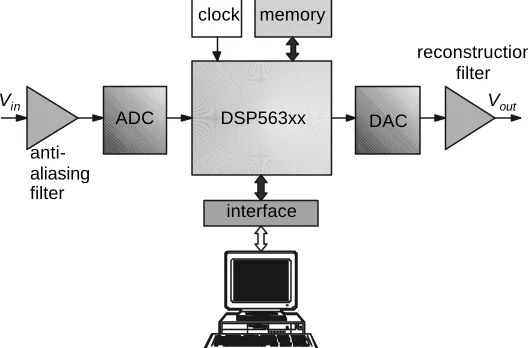
We have designed and evaluated a number of real-time systems based around the Motorola DSP56K and DSP563xx families. In general, these are all advanced 24-bit fractional-arithmetic, fixed-point processors, with 56-bit intermediate resolution, operating at speeds between 33 Million Instructions per second (MIPS) and 360 MIPS. They have highly parallel architectures, treating program memory space separately from data memory space. This is known as Harvard architecture. This concept has been extended further by sub-classifying the data space into X-data memory and Y-X-data memory. The reason this has been done is because many signal-processing algorithms utilize two distinct signal vectors. For example, FIR filters require memory to hold the incoming signal, and memory to hold the filter coefficients; FFT routines require memory to hold the real and imaginary Fourier components, and so on. Operations that traditionally require many instructions to code can be implemented here very compactly, since the details are implemented in hardware. For example, a complete FFT routine requires only 40 words, ie 120 bytes. In contrast, an FFT routine written on a conventional PC might require several thousand bytes. Many complex DSP routines can thus be held in their internal program memories with no requirement for external memory circuits. Several of the latest generation of these devices also incorporate an enhanced filter coprocessor (EFCOP), which is a programmable complex filter module, optimized for high-speed implementation of multi-channel FIR, IIR and adaptive algorithms, with minimal intervention from the core CPU. In practice, this means that the fastest of this family can execute a 8163-tap filter for an audio signal sampled at the standard CD rate of 44.1kHz. In addition to the core processor, the systems we have developed incorporate 18-bit stereo sigma-delta ADCS and DACs, timing and control circuitry for varying the sample rate, external memory and an interface unit to allow the system to communicate with a standard PC via the serial port. This is shown in Figure 1.
DSP563xx
ADC DAC
clock memory
interface
anti-aliasing filter
reconstruction filter
Vout
[image:3.596.165.429.498.672.2]Vin
Figure 1. Major components of the real-time DSP hardware
HIGH-LEVEL AND LOW-LEVEL SYSTEM SOFTWARE
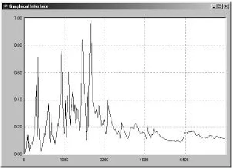
routines are currently under development. Once the filter has been designed (a process that may take no more than a few seconds), the coefficients are downloaded to the unit where the low-level firmware operating performs the convolution operation, in addition to allowing the user to make runtime gain and sampling rate changes. Figure 2 shows a screenshot of the user interface.
Figure 2. The user interface for the real-time DSP system
APPLICATIONS
Stringed instrument emulation
One of the most useful features of these systems is their ability to reproduce an arbitrary-shape frequency response. This is expressed as a text file and imported into the interface, whereupon the software converts it into an FIR coefficient vector for downloading and processing. This provides a powerful, real-time tool for exploring the psychoacoustic properties of acoustic instruments. A violin body, for example, is a linear system; the only non-linearities derive from the player, and how he or she moves the bow across the strings. The force acting on the bridge is to a close approximation a saw tooth function, whose spectral characteristics are then coloured by the frequency response of the bridge and body [6]. It is a simple matter to obtain this response and express it in a form suitable for the DSP system. Our initial work has shown that by feeding the (programmed) system with a string signal acquired from the bridge of a violin (Figure 3), it is possible to generate a convincing acoustic violin. Further studies are now underway using string-vibration signals from guitar playing, processed through graduated sets of simulated resonances, and using standard listener evaluation techniques to determine the just-noticeable difference for various parameters of resonance frequencies and damping factors.
Echo, reverberation and sound field processing
Algorithms for generating echo and reverberation are almost always based on a combination of linear IIR and FIR convolution structures; for example, the classic reverberation algorithm comprises a parallel set of IIR all-pass comb filters with an FIR feedback section [7]. Similarly, sound field processing relies heavily on the introduction of phase delays within specific audio channels and critical frequency bands. The DSP systems now under development are based on a modular, parallel processing structure, with each module performing a specific audio processing task.
Signal equalization and deconvolution
The current version of the DSP system has the ability to import a frequency response, invert it,
take its inverse Fourier transform and use the resulting impulse response as an inversefilter.
This has proven a very useful feature both for sound equalization (for instance, room acoustics), and for waveform shape recovery. Essentially, the algorithm is based around a very simple inversion equation given by
+
=
−s
H
F
t
h
)
(
1
)
(
~
1ω
(7)where H(ω) represents the frequency response of the degrading system an s is a noise term.
Signal recovery in the time domain is affected by
)
(
~
*
)
(
)
(
t
y
t
h
t
x
=
(8)in which x(t) is the recovered signal and y(t) is the input (degraded signal). Despite the simplicity
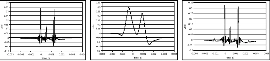
[image:5.596.84.514.448.546.2]of the algorithm, it has proven very useful for equalization and pulse-recovery purposes. Figure 4(a) for example, shows three pulses three pulses generated by a sound card (the ripples are a function of the impulse generation software and the frequency response of the sound card). Figure 4(b) shows what happens when the pulses pass through a system with a low frequency cut-off point of around 1kHz. The signal has been degraded so badly that it is impossible to distinguish the middle pulse, and the two remaining ones are spread out in time. Figure 3(c) shows the restored signal; not only has the temporal relationship between the three values been precisely restored, so too in large measure have their amplitudes.
Figure 4. Use of the DSP system in signal recovery; (a) original set of three pulses; (b) pulses after degradation; (c) restored pulse train using real-time inverse filter.
Brick-wall filtering
The system allows the operator to design a simple brick-wall filter by entering the cut-off point, the number of taps and the sample rate. Such a filter, with an upper cut-off of 3.1kHz, was used to recover a tone burst signal buried in wide-band noise, shown in Figure 5(a). The noise in this instance had a flat bandwidth extending from 3.2kHz to 20kHz. Figure 5(b) shows the recovered signal, which comprised a mix of two sinusoids at 2.85kHz and 3kHz. Although the recovery looks impressive, digital filters do this job very easily. Since the bandwidth of the noise does not encroach on the signal bandwidth, total signal restoration is possible as long as the filter is sharp enough with pure phase linearity.
-0.15 -0.1 -0.05 0 0.05 0.1 0.15 0.2 0.25 0.3 0.35 0.4
-0.003 -0.002 -0.001 0 0.001 0.002 0.003 0.004 time (s)
volts
-0.2 -0.15 -0.1 -0.05 0 0.05 0.1 0.15 0.2 0.25 0.3 0.35
-0.003 -0.002 -0.001 0 0.001 0.002 0.003 0.004 time (s)
volts
-0.1 -0.05 0 0.05 0.1 0.15 0.2 0.25 0.3 0.35
-0.003 -0.002 -0.001 0 0.001 0.002 0.003 0.004 time (s)
Figure 5. Signal recovery using brick wall filtering; (a) signal degraded by noise;(b) signal after noise removal.
Analogue filter frequency response emulation
Analogue filter frequency responses may be realized and executed as FIR structures. This confers the advantages of total stability and pure phase linearity, regardless of order. The frequency response of a Butterworth filter is given by
(
)
[
]
12
/
1
)
(
)
(
−
+
=
nc in
out
f
f
f
v
f
v
(9)
where fc represents the cut-off point. This kind of filter has a roll-off of 6n dB per octave, where n
represents the order, or number of poles, of the filter. The design of a low-pass 18-pole Butterworth filter for example (ie with a roll-off of 108dB per octave), only requires the user to select the order, the cut-off point and the sampling rate. The software will automatically calculate the impulse response, which can then be used for both real-time and off-line processing. These DSP systems are so fast that they will easily handle much higher orders of filter – 60, 70, 80 poles or more, without error. In addition it is also possible to design and use
fractional order filters, since the impulse response calculation, and the filter implementation, is strictly a matter of software.
DISCUSSION AND CONCLUSION
The initial studies we have conducted with stringed instruments show that real-time DSP systems make it possible to perform experiments that were once either too cumbersome to realize in practice, or in some instance, completely impossible. There are two principal reasons for this: first, the enormous processing speeds of modern digital systems enable non-analytical or arbitrary frequency responses to be replicated in real-time using FIR structures; second, careful attention to both hardware and software engineering ensures that a system’s real-time performance may be completely altered within a short space of time (seconds, or minutes at the most), using keyboard commands. These features are in stark contrast with analogue designs, in which arbitrary responses may only be approximated; in addition, altering a system’s performance often involved hardware changes. Our experience suggests that most scientists who employ DSP in their work are conversant with the electronics, the real-time language processing and the mathematics associated with filter design and convolution. However, we realize that there are many areas of enquiry that would benefit enormously from the application of this real-time technology, but whose practitioners do not have time to expend in learning the details of systems and algorithm design. These intelligent platforms that should enable users to take rapid advantage of digital methods by focusing on the objective, rather than the means required to realize it.
REFERENCES
1. Ifeachor E C, Jervis B W, Moris E L, Allen E M and Hudson N R 1986 A new
microcomputer-based online ocular artefact removal (OAR) system, Proc. IEE, 133(5), 291-300
2. Sodke R 1996 DSP in medical image processing - a case study, EDN, 41(23A), 44
3. Murphy C D and Anandakumar K 1997 Real-time MPEG-1 audio coding and decoding on a
DSP chip, IEEE Trans. on Consumer Electronics,43(1), 40-47
4. Baccigalupi A, Bernieri A and Pietrosanto A 1997 A digital-signal-processor-based
measurement system for on-line fault detection, IEEE Trans. on Instrumentation &
Measurement,46(3), 731-736
5. Place A G and Allen G H 1997 Generalized pole sensitivity analysis due to parameter
perturbation, IEEE Trans. on Circuits and Systems,44(10), 869-873
6. Cremer, L., 1985, The physics of the violin: MIT Press, Cambridge, Mass.