Evaluation of a Long Term System coupled with a
Short Term System of a Hydrogen-Based Microgrid
Alvaro Serna Fernando Tadeo Dpto. Systems Eng. and
Automation Univ.of Valladolid
Valladolid, Spain alvaro.serna@autom.uva.es
fernando@autom.uva.es
Imene Yahyaoui Dpto. Electric Eng. Federal Univ. of Espírito Santo
Vitória, Brazil imene.yahyaoui@ufes.br
Julio E. Normey-Rico Dpto. Automation and Systems Federal Univ. of Santa Catarina
Florianópolis, Brazil julio.normey@ufsc.br
Felix Garcia-Torres Simulation and Control Unit
Hydrogen National Center Puertollano, Ciudad Real,
Spain felix.garcia@cnh2.es
Abstract— Coupling of a Long Term System (LTS) with a
Short Term System (STS) of a hydrogen-based microgrid is considered here in this work to control the operation of a set of electrolyzers that produce hydrogen from renewable energies. Both systems are based on Model Predictive Control (MPC) ideas. The LTS manages the on/off conditions of the electrolyzers taking into account control and prediction horizons in terms of hours (high level control), regulating the operation point of the devices using meteorological predictions. The STS adapts in a low-level control the behavior of the electrolyzers with the rest of the components of the microgrid (battery and ultracapacitor). The plant is modeled in the Mixed Logic Dynamic (MLD) framework due to the presence of logical states such as the start-up/shut down of the electrolyzers and charge/discharge states in the battery and ultracapacitor. These systems are validated in a simulation showing the adequate operation of the components of the microgrid.
Keywords—electrolysis; predictive control; microgrid; energy management system.
I. INTRODUCTION
Hydrogen economy is being very popular the last few years because it can be developed for everyday life devices and implemented in hydrogen cars or local energy consumptions [1]. Hydrogen-based microgrids can be a useful alternative for isolated locations as they provide energy without the need of fuel fuels and electricity grid [2]. High energy density of hydrogen as an energy carrier will play an important role in this new energetic paradigm [3], especially because fuel cells can operate in houses as generators with the advantage of the lack of CO2 emissions. Obtaining energy from renewable sources
such as photovoltaic [4], wind [5] or waves [6] has been studied in several papers. The usefulness of these energy sources has been verified, the principal problem being their variability, therefore the most difficult inconvenient to solve is the control and manage of these microgrids. In this work, we focus on a combination of wind and wave’s energy sources as their variability with respect to photovoltaic or another renewable sources is smaller thanks to the low temporal correlation of the resources [7]. Electrolyzers are used here to
produce H2, as it enables the production of H2 directly from
electrical power and they are easily available in the market. Advanced control of microgrids has been developed since the last years [8,9]. Lin and Zheng [10] propose a strategy based on adaptative control using neural networks. Different studies associated to management of microgrids with hybrid storage propose the hysteresis method [11,12] where the electrolyzers are activated depending on the state of charge (SOC) of batteries and ultracapacitors. More specifically, MPC has been used [13] to solve the problem of connections/disconnections of the electrolyzers and its integration with storage devices such as batteries or ultracapacitors. The term MPC does not designate a specific control strategy, but a very ample range of control methods which make an explicit use of a model of the process to obtain the control signal by minimizing an objective function [14, 15]. MPC Controller has been applied with satisfactory results in the hybridization of this type of microgrids in several papers, such as that carried out by Vahidi and Greenwell et al [16]. Patterson et al [17] explore solutions for microgrids with electrical vehicles. The optimal use of the microgrid requires the development of a controller which takes into account all the constraints, limitations, degradation issues and the economic cost of each system of the microgrid.
In comparison with previous work [3], in this paper energy sources chosen are wind and waves, so the profile is more stable because wave energy is more continuous. Therefore, microgrids similar to the one proposed here can be installed in isolated coastal locations. Different electrolyzers are defined in the case study proposed here, so the algorithm tries to choose the best performance of the microgrid. Another difference with [3] is that the high level control is based on the production and consumption of the electrolyzers and not with an economical dispatch. Electrolyzers depend on only certain constant parameters, so the case study can be modified by only adjusting these parameters.
In this paper, the performance of a hydrogen-based microgrid composed by renewable sources, electrolyzers, batteries and an ultracapacitor is developed, solved and experimentally validated in a simulation. The start-up sequences of the electrolyzers are also considered and This work was funded by Ministerio de Ciencia e Innovación
DPI2014-54530-R and DPI2014-46912-C2-1-R (Project COOPERA). H2Ocean received funding from the European Union Seventh Framework
controlled with the use of logical variables. Combination of the high-level control and the low-level control published in [3] and [15] respectively is the main contribution of the article. The paper is organized as follows: Section II describes the microgrid with an explanation of the components, models and variables. Sections III presents the LTS proposed as a high-level control while Section IV proposes the STS as the low-level control. Section V presents and discusses the results of the MPC controllers in the microgrid. Finally, Sections VI outlines the conclusions.
II. HYDROGEN-BASED MICROGRID
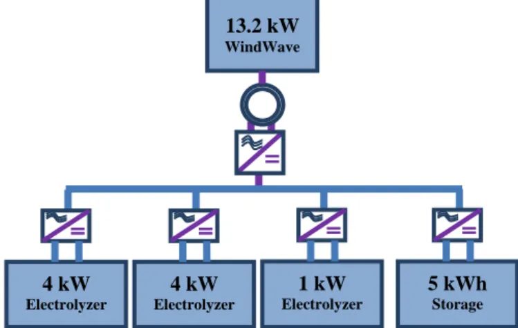
The scheme of the renewable hydrogen platform is depicted in Fig.1. Energy sources (wind and wave) are renewable and can be obtained easily in coastal locations. Electricity produced is supply to a set of electrolyzers that transform water (H2O) into
hydrogen (H2).
Fig. 1. Block structure of the renewable hydrogen platform.
The microgrid proposed in this paper has three electrolyzers (two high production and one small production for residual power values). Moreover, for certain times when available renewable power is not enough for the electrolyzers operation, a battery and an ultracapacitor are included to supply energy to the electrolyzers. Finally, hydrogen produced can be given to users for be used as input in fuel cells or for different needs.
A. Electrolyzers
An electrolyzer is an electrochemical device (it uses electricity and chemistry at the same time) designed to perform electrolysis: splitting a solution into the atoms from which it is made by passing electricity through it [18]. Different types of electrolyzers have been developed since the last years, being alkaline electrolyzers the most available at the market [19]. In this paper two variables are defined in the electrolyzers operation: one is the operating points for each electrolyzer. It is mathematically denoted by αi(k), where k represents the
discrete time in samples and the suffix i is used to identify each device. Moreover:
a) αi(k)|i=ele= 0 if the device i is disconnected at time k. b) αi(k)|i=ele is between [ αi α̅i] if the electrolyzer is
connected, where αi and α̅i are minimum and maximum
values (between 0 and 1) fixed by the manufacturer due to technological limitations.
Another variable is the binary variable δi(k)|i=eleϵ {0,1}
where 0 corresponds to electrolyzer disconnection and 1 to electrolyzer connection.
B. Batteries and ultracapacitor
Batteries are one of the storage devices chosen for this microgrid. They have degradation issues that must be avoided such as the formation of permanent oxides during the charge of the battery pack at high SOC. The shorter the discharge (low depth of discharge DoD), the longer the battery will last. Since these processes are diffusion controlled and slow, it is necessary that a low charging rate is used [3]. The rate capability loss is proportional to the value of the average current used [20]. Ultracapacitors are the other type of energy storage selected in this work. They have low energy density and behave as a short circuit when are exposed to low levels of state of charge [21]. High SOC can also damage this technology [22]. The model of the ultracapacitor has complex equations to be linearized as detailed in [23], but the voltage dynamic is quite slower than for the current for the selected sample time Ts=1s. Therefore, the approximation considered in equation (1) will be included in the MPC controller. The same assumption can be done for the case of the batteries [3].
Ui(tk+1) = Ui(tk+1)|i=uc,bat (1)
The charge and discharge power of the batteries and the ultracapacitor can be expressed as:
Pidis(t
k)|i=uc,bat= {
Pi(tk) Pi(tk) ≥ 0
0 Pi(tk) < 0} (2)
Pich(tk)|i=uc,bat= {
0 Pi(tk) > 0
Pi(tk) Pi(tk) ≤ 0} (3)
Both devices have also the logical states for the charge (δich) and discharge (δidis) for the batteries and ultracapacitor. The capacity of the ultracapacitor and the batteries can be modeled with the next equation:
Ci(tk+1) = Ci(tk) + (Ich,i(tk+1) −Iidis(t
k+1)) ∙ Ts|i=uc,bat (4)
The relationship between the charging and discharging current and the corresponding charging and discharging power are [3].
Iich(tk+1) =
Pich(tk+1)∙ηich
Ui(tk) |i=uc,bat (5)
Iidis(tk+1) =
Pidis(tk+1) Ui(tk)∙ηidis
|i=uc,bat (6)
Finally the state of charge of the batteries is given by the next expression:
SOCi(tk+1) = Ci(tk+1)
Cimax |i=uc,bat (7) 4 kW
Electrolyzer
4 kW Electrolyzer
1 kW Electrolyzer
5 kWh Storage 13.2 kW
III. LONG TERM SYSTEM (LTS)
The control algorithm designed in this system aims to maximize the H2 produced by electrolysis considering
different aspects, such as the limitation in the available renewable power and the operational constraints. Available power is obtained by meteorological predictions such as wind speed, wave height and wave period.
Ĥi(k) =
α̂i(k)∙δ̂i(k)
a∙α̂i(k)+b |i=ele(LTS)
P
̂i(k) = P̅i∙ α̂i(k) ∙ δ̂i(k)= z(k)|i=ele(LTS)
Equations (8) and (9) show the controlled variables of electrolyzer i: P̂i(k) and Ĥi(k). On the one hand, Ĥi(k) is the
predicted H2 production of electrolyzer i at time k. On the
other hand, P̂i(k) is the predicted energy consumption of
device i and P̅i is its maximum power at the same sample time. Parameters ai, bi and P̅i are used to define the device performance. This performance is called the relationship between consumed energy and H2 production. Note that the
model of the electrolyzers is static because the time required for them to vary α from the minimum to the maximum value is less than a few minutes in the worst case, thus, these dynamics can be neglected as the sampling time for the LTS proposed here is one hour.
A. Long Term MPC design
Equation (10) shows the quadratic cost function considered in this system, which is minimized at each sample time to find the optimal control action. This equation considers, in prediction and control horizons of N and Nu samples
respectively, the error between the predictions of H2 produced
(Ĥi) and the desired values (H̅i), while also penalizing the
number of connections and disconnections. Besides, QHi and Qδi are the weighting factors for the error and the control
action, respectively [15].
J = ∑i=1n |i=ele∑Nj=1[(Ĥi(k + j) − H̅i(k + j))2QHi
+ ∑ni=1∑Nuj=1(δ̂i(k + j) − 1)2Qδi] (10)
B. Control objectives of the LTS
Two objectives must be fulfilled to maximize H2
production considering the limitation of the available power and operational constraints [15]:
To maximize H2 production, the difference between
the values of the prediction (Ĥi) and its desired values
(H̅i) is minimized for all the electrolyzers along the prediction horizon (N).
To maximize the operation of the electrolyzers (α), the
discrete variables defining the
connection/disconnection condition (δ) should be, whenever possible, equal to one along N. Energy
consumed by the electrolyzers should always be smaller than the energy supplied from the renewable sources but will try to be equal.
The first term of (10) is used for the first objective, while the second term of this equation tries to achieve the second. To solve this problem, the future predictions of the H2
production are expressed as a function of the future control actions and the past values of the input and outputs using the electrolyzer models. Thus, using equation (10) with all the system constraints and the electrolyzer models, it can be shown that the optimization problem to be solved at each sample time is (11).
min(αi,δi)J (11)
st: δi ∈ [0, 1] |i=ele(LTS) αi ≤ αi ≤ α̅i|i=ele(LTS)
P̂i(k) = P̅i∙ α̂i(k) ∙ δ̂i(k) |i=ele(LTS)
Ĥi(k) = α̂i(k)∙δ̂i(k)
a∙α̂i(k)+b |i=ele(LTS)
∑n P̂i(k) ≤ P̂available(k)
i=1 |i=ele(LTS)
This high-level control provides continuous (αi) and
discrete (δi) values of the electrolyzers [15]. These values are then used as inputs in the low-level control system which is explained in the section below.
IV. SHORT TERM SYSTEM (STS)
This control system tries to eliminate fluctuations in the current applied to electrolyzers which produce several degradation mechanisms [24]. The electrolyzer management system (ELMS) designed feed the stack with enough water to produce the electrolysis reaction [3]. The procedure of the startup sequence takes the EMLS a starting time of 10 s for the high production and 2 s for the small production electrolyzers before it can absorb energy form the microgrid.
As there are logical states in the electrolyzers, it makes necessary to introduce logical, dynamic and mixed variables. The first variable to be introduced must be the energized state of the electrolyzer. It is defined by the logical variable δi|i=ele(STS) whose value is set to 1 in this state and 0 in the
rest of the states of the electrolyzers. Owing to the starting-up sequence (δi(tk)|i=ele(STS)) must be expressed as function of
the logical control signal to switch on/off the electrolyzers Λi(tk)|i=ele(STS). The devices just reach the energized state if Λi(tk)|i=ele(STS) is active in all the instants of the required time φi(tk)|i=ele(STS) for the starting sequence [3]. The
relationship between δi(tk)|i=ele(STS) and Λi(tk)|i=ele(STS) is defined by equation (12):
δi(tk) = 1 ↔ φi− ∑ (Λi( sj=φi
sj=0 tk− sj))|i=ele(STS)≤ 0 (12)
and (14), where coefficients m, M and ε follow the notation given in [34].
φi− ∑sj=φi(Λi(
sj=0 tk− sj)) ≤ M − Mδi|i=ele(STS)≤ 0 (13)
φi− ∑sj=φi(Λi(
sj=0 tk− sj)) ≥ ε + (m − ε)δi|i=ele≤ 0 (14)
The start-up ( σjon(tk)) and shut-down ( σjoff(tk)) states for
the devices are defined in equations (15) and (16).
σjon(tk) = max(Λj(tk) − Λj(tk−1),0)|j=ele(STS) (15)
σjoff(t
k) = max(Λj(tk−1) − Λj(tk),0)|j=ele(STS) (16)
Electrolyzers would be only able to consume the energy in the microgrid in the energized state. So the logical power zeleSTS
is defined by the equation (17) as product of the power reference value and the logical on/off state giving as results the introduction of MLD constraints in the controller.
zj(tk) = Pj(tk) ∙ δj(tk)|j=ele(STS)= zeleSTS (17)
When the energized state is reached, the controller must provide a reference as function of the schedule. The remaining power in the microgrid must be maintained later on in order to minimize the power fluctuations of the electrolyzers which can drive to degradation conditions over these devices. Thus, the logical power variation ϑj(tk) is defined as the power
variation in all the instants less those when the device passes from the start-up state to the energized state [3]. The energy source in the microgrid is the power available (Pavailable) from
the hybrid wind and wave device. Different wind and wave energy models can be found in literature. The sample time established for the controller is Ts= 1s. In this time-order the
dynamic of the generators for all the sample instants of the control horizon (j=1,2…15) can be assumed constant and equal to the sampled value. The next power prediction is introduced in the controller.
Pavailable(tk+j) = Pavailable(tk) (18)
A. Short Term MPC design
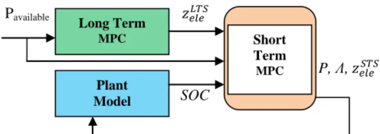
Fig.2 depicts the block diagram for the MPC Controller. This controller receives as reference the operation points and binary variables of the microgrid for the batteries and the electrolyzer. While the high level control explained in section III has a control horizon of 1 hour, the Load Sharing MPC Controller has a control horizon of 15 s (value taken due to the start sequence of the electrolyzer) and a Ts =1s.
Pavailable 𝑧𝑒𝑙𝑒𝐿𝑇𝑆
P, Λ, 𝑧𝑒𝑙𝑒𝑆𝑇𝑆
SOC
Fig. 2. Block structure of the Short Term System.
Different weighting factors (wi) and constraint limits of the components of the H2 microgrid have been defined for the
case study. The weighting factor assignment criterion has been equivalent as for the LTS. Physical constraints are given by the upper and lower limit power that the system can absorb. Bemporad and Morari [25] conversion makes it possible to include binary and auxiliary variables into a discrete-time dynamic system in order to describe in a unified model the evolution of the continuous and logic signals of the system [3].
B. Control objectives of the STS
The main cost function in this control level is based on the deviation from the power references and the energy stored level from the LTS control of the microgrid. With the objective of give a freedom grade to the system, the ultracapacitor is just referenced to an intermediate SOC. In all the function cost applied to each component, degradation or anomalous working conditions are avoided, introducing these terms in the objective function of the controller as it will be explained in the next sections [3].
min J (tk+1) = Juc(tk+1) + Jbat(tk+1) + Jele(tk+1) (19) Ultracapacitor cost function
Equation (18) depicts the cost function of the ultracapacitor. The ultracapacitor is kept in an intermediate SOC in order to be always available if required to compensate the rest of components of the microgrid. This allows also protecting it from undercharge or overcharging. The second term of the cost function is added to avoid instability points in the ultracapacitor giving a low weighting factor but giving zero as power reference value for the ultracapacitor. If this term had not been included, sub-optimal problem solutions would have been found when the power calculated by the solver is close to zero.
Juc(tk+1) = ∑15j=1(wucE (SOCuc(tk+j) − SOCucref(tk+j))2+ (wucP ∙
(Puc(tk+j) − 0)2) (20)
Battery cost function
Equation (21) shows the battery cost function. Batteries are more flexible than other devices due to the fact that start-up and shut-down cycles do not affect to this technology. The last term of the cost function penalizes the AC current in the batteries.
Jbat(tk+1) = ∑(wbatP 15
j=1
(Pbat(tk+j) − PbatLTS(t
k+j))2 +
wbatE (SOCbat(tk+j)−SOCbatLTS(tk+j))2 +
wbatripple(∆Pbat(tk+j))2) (21) Electrolyzer cost function
Equation (22) defines the electrolyzer cost function. As well as in the case of the battery, the output of the high level control of the microgrid gives the reference in power at each Short
Term
MPC
Long Term
MPC
instant. In order to protect from the main causes of degradation, the start up and shut down states are penalized in the controller.
Jele(tk+1) = ∑15j=1(weleP ( zeleSTS(tk+j) − zeleLTS(tk+j))2+
weleripple(ϑele(tk+j))2+ wele startup
∙ σeleon(tk+j) + weleshutdown∙
σeleoff(tk+j)) (22)
V. CASE STUDY
To produce the energy for the renewable H2 microgrid, two
sources (wind and wave) have been considered in this case study. Two hybrid devices of 1 vertical axis wind turbine (VAWT) of 5.0 kW peak power and 1 wave energy converter (WEC) of 1.6 kW peak power were chosen according to the studies developed in the project H2Ocean [26]. These hybrid VAWT-WEC devices (shown in Fig.3) are assumed to provide the energy.
Fig. 3. A co-located hybrid VAWT-WEC device [27].
To produce H2, two 4kW and one small production 1kW
NITIDOR electrolyzers were chosen. The alkaline electrolyzers operate slightly above ambient pressure and are further equipped with pressure relief equipment, to prevent overpressure operation.
A. Controller implementation
As it was said in the section below, the outputs of the LTS Controller are the inputs of the STC Controller with the variables of the plant model. LTS gives the references of the operating points of the electrolyzers and the battery performance considering the power available which comes from the hybrid device. Available power is obtained by meteorological data from a certain location in the north of the Atlantic Ocean. Then, the STS calculate control parameters defined in section IV and return to the model plant. Simulation and optimization is done for each sample time of 1 s.
B. Results and discussion
For this case study, some results for 8 hours can be observed in the following figures. Fig. 4 shows the power profile of the hybrid wind and wave device. As it can be seen, this profile is smoother than other work before [3] due to the characteristic behavior of wave energy.
Fig. 4. Available renewable power profile.
Fig. 5 depicts the performance of the three electrolyzers that produce H2. As it can be observed, they do not switch
on/off frequently so the control system can be considered appropriate. The different behavior of the electrolyzers is because each one has their own weighting (w), but they follow the same trend than the available power. Elz 1 and 2 are the high production electrolyzers while Elz 3 is the small production device which supply power for residual values.
Fig. 5. Electrolyzers performance.
Fig. 6 shows the power that gives/receives the storage devices (battery and ultracapacitor) along the simulation. They receive power when there is an excess of available energy because the electrolyzers operate at a 100% of performance (between 5th and 6th hours in the case study). In other hand, the provide power to produce H2 when there is a lack of renewable
energy.
Fig. 6. Power exchange of the battery and ultracapacitor.
Finally, Fig. 7 depicts SOC values of the same storage devices. They meet minimum and maximum constraints therefore it can be considered as well designed. Moreover, it can be seen that the variation of the SOC is very smooth, thus lifetime of this devices is ensured to be improved in comparison with other heuristic control systems.
Fig. 7. Battery and ultracapacitor SOC.
VI. CONCLUSIONS
In this paper, MPC controllers for long and short term of a hydrogen-based microgrid have been coupled and validated in a simulation. This formulation integrates the penalties of
0 1 2 3 4 5 6 7 8
-1 -0.5 0 0.5 1 1.5 2
Time (hours)
P
o
w
e
r
(k
W)
Bat Uc
0 1 2 3 4 5 6 7 8
0 0.2 0.4 0.6 0.8 1
Time (hours)
S
O
C
Bat Uc
0 1 2 3 4 5 6 7 8
0 1 2 3 4 5
Time (hours)
P
o
w
e
r
(k
W) Elz 1
Elz 2 Elz 3
0 1 2 3 4 5 6 7 8
0 2 4 6 8 10 12
Time (hours)
P
.
A
v
a
ila
b
le
(
k
degradation situations, considering all the components of the microgrid (electrolyzers, batteries and ultracapacitor).
The Mixed-Integer-Quadratic-Programming for the MPC controllers optimizes the operation of the electrolysis set. The discrete variables define the connection/disconnection condition of the electrolyzers and the storage devices acting along the prediction horizon. State of health of the electrolyzers, battery and ultracapacitor is ensured, thanks to the minimization of the switching between the connection/ disconnection states.
ACKNOWLEDGMENT
This work was supported by Ministerio de Ciencia e Innovación under grant DPI2014-54530-R and the European Commission (7th Framework Programme, grant agreement 288145, Ocean of Tomorrow Joint Call 2011). A. Serna thanks the financial support given by Junta de Castilla y León EDU/1083/2013. This work was carried out financed by a mobility grant given by Universidad de Valladolid (Call 2016). Dr Félix García-Torres thanks Ministry of Economy and Competitiveness of Spain for the financial support under grant DPI2014-46912-C2-1-R (Project COOPERA). Prof. Normey-Rico thanks CNPq-Brazil for financial support under projects 305785/2015-0 and 401126/2014-5.
REFERENCES
[1] C.J. Winter, J. Nitsch, “Hydrogen as an energy carrier: technologies, systems, economy”. Springer Science & Business Media. 2012. [2] C. Wang, X. Yang, Z. Wu, Y. Che, L. Guo, S. Zhang, Y. Liu, “A highly
integrated and reconfigurable microgrid testbed with hybrid distributed energy sources”. IEEE Transactions on Smart Grid, 7(1), 451-459. 2016 [3] F. Garcia-Torres, L. Valverde, C. Bordons, “Optimal load sharing of
hydrogen-based microgrids with hybrid storage using moel predictive control”. IEEE Transactions on Industrial Electronics, 63(8), 4919-4928. 2016.
[4] S. Jiménez-Fernández, S. Salcedo-Sanz, D. Gallo-Marazuela, G. Gómez-Prada, J. Maellas, A. Portilla-Figueras, “Sizing and maintenance visits optimization of a hybrid photovoltaic-hydrogen stand-alone facility using evolutionary algorithms”. Renewable Energy, 66, 402-413. 2014.
[5] M. Beccali, S. Brunone, P. Finocchiaro, J.M. Galletto, “Method for size optimisation of large wind–hydrogen systems with high penetration on power grids”. Applied energy, 102, 534-544. 2013.
[6] A. Serna, F. Tadeo, D. Torrijos, K. Touati, “Evaluation of wave energy for a near-the-coast offshore desalination plant”. In Proceedings of the IDA World Congress on Desalination and Water Reuse. (2013, October).
[7] E.D Stoutenburg, N. Jenkins, M.Z. Jacobson, Power output variations of co-located offshore wind turbines and wave energy converters in California. Renewable Energy, 35(12), 2781-2791. 2010.
[8] J.M Guerrero, M. Chandorkar, T.L. Lee, P.C. Loh, “Advanced control architectures for intelligent microgrids, part I: decentralized and hierarchical control”. IEEE Transactions on Industrial Electronics, 60(4), 1254-1262. 2013.
[9] M. Yazdanian, A. Mehrizi-Sani, “Distributed control techniques in microgrids”. IEEE Transactions on Smart Grid, 5(6), 2901-2909. 2014. [10] W.S Lin, C.H. Zheng, “Energy management of a fuel cell/ultracapacitor
hybrid power system using an adaptive optimal-control method”. Journal of Power Sources, 196(6), 3280-3289. 2011.
[11] A. Arce, J. Alejandro, C. Bordons, “MPC for battery/fuel cell hybrid vehicles including fuel cell dynamics and battery performance improvement”. Journal of process control, 19(8), 1289-1304. 2009. [12] Ø .Ulleberg, “The importance of control strategies in PV–hydrogen
systems”. Solar Energy, 76(1), 323-329. 2004.
[13] F. Garcia-Torres, C. Bordons, “Optimal economical schedule of hydrogen-based microgrids with hybrid storage using model predictive control”. IEEE Transactions on Industrial Electronics, 62(8), 5195-5207. 2015.
[14] E.F Camacho, C.B Alba, (2013). “Model predictive control”. Springer Science & Business Media. 2013.
[15] A. Serna, I. Yahyaoui, J. E. Normey-Rico, C. de Prada, F. Tadeo, “Predictive control for hydrogen production by electrolysis in an offshore platform using renewable energies”, International Journal of Hydrogen Energy. 2016. http://dx.doi.org/10.106/j.ijhydene.2016.11077 [16] A. Vahidi, W. Greenwell, “A decentralized model predictive control
approach to power management of a fuel cell-ultracapacitor hybrid”. In Proceedings of the IEEE 2007 American Control Conference (pp. 5431-5437). (2007, July).
[17] M. Patterson, N.F. Macia, A.M. Kannan, “Hybrid microgrid model based on solar photovoltaic battery fuel cell system for intermittent load applications”. IEEE Transactions on Energy Conversion, 30(1), 359-366. 2015.
[18] M. Khalid, A.V. Savkin, “A model predictive control approach to the problem of wind power smoothing with controlled battery storage”. Renewable Energy, 35(7), 1520-1526. 2010.
[19] F. Mueller-Langer, E. Tzimas, M. Kaltschmitt, S. Peteves, “Techno-economic assessment of hydrogen production processes for the hydrogen economy for the short and medium term”. International Journal of Hydrogen Energy, 32(16), 3797-3810. 2007.
[20] G. Sikha, P. Ramadass, B.S. Haran, R.E. White, B.N. Popov, “Comparison of the capacity fade of Sony US 18650 cells charged with different protocols”. Journal of Power Sources, 122(1), 67-76. 2003. [21] L.A.F. Oropeza, O.G. Suárez, “Estudio y análisis de soluciones
topológicas de convertidores CC-CC bidireccionales para su aplicación en vehículos hibridos”. PhD Dissertation, Univ. Politécnica de Madrid, Madrid 2004.
[22] S.V Rajani, V.J Pandya, V.A Shah, “Experimental validation of the ultracapacitor parameters using the method of averaging for photovoltaic applications”. Journal of Energy Storage, 5, 120-126. 2016.
[23] M.E. Glavin, P.K. Chan, S. Armstrong, W.G. Hurley, “A stand-alone photovoltaic supercapacitor battery hybrid energy storage system”. In Proceedings of the 13th IEEE Power Electronics and Motion Control Conference, EPE-PEMC 2008 (pp. 1688-1695). (2008, September). [24] J. Milewski, G. Guandalini, S. Campanari, “Modeling an alkaline
electrolysis cell through reduced-order and loss-estimate approaches”. Journal of Power Sources, 269, 203-211. 2014.
[25] A. Bemporad, M. Morari, “Control of systems integrating logic, dynamics, and constraints”. Automatica, 35(3), 407-427. 1999. [26] H2Ocean-project.eu. 'H2ocean'. N.p., 2016. Web. 8 December 2016.
Available at http://www.h2ocean-project.eu/.