PhD Thesis
FORMULATION OF ANTICORROSIVE PAINTS
EMPLOYING CONDUCTING POLYMERS
MIREIA MARTÍ BARROSO
Supervisors:
Dr. Elaine Armelin Diggroc
Dr. Carlos Alemán Llansó
BARCELONA, JUNE 2013
DEPARTAMENT D’ENGINYERIA QUÍMICA
Als que hi són i hi seran fins al final,
Acknowledgements
I am heartily thankful to my supervisors, Elaine Armelin and Carlos Alemán, for their encouragement, guidance and support from the start to the end of this project.
I also would like to thank specially Dr. A. Meneguzzi for his assistance with the Raman analysis, David Aradilla for the SEM measurements, Mª Teresa Casas for TEM microscopy and Dr. D.S. Azambuja and Georgina Fabregat for electrochemical measurements.
Lastly, I offer my gratitude to all of those who supported me during the completion of the project, especially to all IMEM’s Group and Chemical Engineering Department, family, friends and workmates.
Glossary
AIBN: Azoisobutyronitrile
Alkyd-PAniEB/0.3: Alkyd primer with 0.3 wt.% of polyaniline emeraldine base Alkyd-PAniES/1: Alkyd primer with 1 wt.% of polyaniline emeraldine salt Alkyd-PTE/1: Alkyd primer with 1 wt.% of poly[2,2’-(3-methylacetate)
thiophene]
Alkyd-Zinc/10: Alkyd primer with 10 wt.% of zinc phosphate CP: Conducting polymer
CPE: Constant phase element CPEc: Coating capacitance
CPEIL: Metal/coating interface capacitance
CPVC: Critical pigment volume concentration Cs: System capacitance
DBSA: Dodecylbenzene sulphonic acid DFT: Dry film thickness
DGEBA: Diglycidyl ether of bisphenol A DGEBF: Diglycidyl ether of bisphenol F DMSO: Dimethyl sulfoxide
DSC: Differential scanning calorimetry E: Electrode potential
E: Elastic (or Young) modulus EC: Equivalent circuit
EIS: Electrochemical impedance spectroscopy EDX: Energy dispersive X-ray
EP-0: Epoxy primer supplied by Pinturas Hempel S.A. completely free of anticorrosive pigments and additives
EP/PT3MDE-0.3: EP-0 primer with 0.3 wt.% of PT3MDE EP/Zn3(PO4)2-10: EP-0 primer with 10 wt.% of Zn3(PO4)2
EPOXY-60: Epoxy primer supplied by Pinturas Hempel S.A. with 60 wt.% of metallic zinc dust
EPOXY-60/PAni: EPOXY-60 primer with 0.3 wt.% of PAni-ES
EPOXY-79: Epoxy primer supplied by Pinturas Hempel S.A. with 79 wt.% of metallic zinc dust
EPOXY-79/PAni: EPOXY-79 primer with 0.3 wt.% of PAni-ES
Epoxy-DMSO/PAni: Epoxy coating formulated with DMSO as solvent and 0.3 wt.% of PAni-EB as anticorrosive additive
Epoxy-DMSO/PTE: Epoxy coating formulated with DMSO as solvent and 1.0 wt.% of PTE as anticorrosive additive
Epoxy-DMSO/Zn: Epoxy coating formulated with DMSO as solvent and 10 wt.% of zinc phosphate as anticorrosive additive
Epoxy-xylene/PAni: Epoxy coating formulated with xylene as solvent and 0.3 wt.% of PAni-EB as anticorrosive additive
Epoxy-xylene/PTE: Epoxy coating formulated with xylene as solvent and 1.0 wt.% of PTE as anticorrosive additive
Epoxy-xylene/Zn: Epoxy coating formulated with xylene as solvent and 10 wt.% of zinc phosphate as anticorrosive additive
EOCP: Open circuit potential
εb: Elongation at break
LbL: Layer-by-layer
LCI: Lowest Concentration of Interest NMPy: N-Methylpyrrole
PA: Polyacetylene
PAni: Polyaniline
PPy: Polypyrrole
PS: Polystyrene
PSS: PS sulfonated
PT3AME: Poly(3-thiophen-3-yl-acrylic acid methyl ester) PT3MDE: Poly(2-thiophen-3-yl-malonic acid dimethyl ester) PTE: poly[2,2’-(3-methylacetate)thiophene]
PTh: Polythiophene
PVC: Pigment volume concentration PVP: Poly(N-vinylpyrrolidone)
Py: Pyrrole
REACH: Registration, Evaluation, Authorisation and Restriction of Chemical substances
Rc: Coating resistance
RCS: Refrigerated cooling system RIL: Metal/coating interface resistance
Rp: Polarisation resistance
Rs: Resistance between working and reference electrodes
SCE: Saturated calomel electrode SEM: Scanning electron microscopy
σmax: Tensile strength
Tc: Crystallisation temperature
TEM: Transmission electron microscopy Tf: Melting temperature
Tg: Glass transition temperature
TGA: Thermogravimetric analysis
Φ: Water uptake
Table of Contents
1.
INTRODUCTION ____________________________________________ 1
1.1. Fundamentals of corrosion ... 3
1.2. Corrosion prevention ... 7
1.2.1. Materials selection ... 7
1.2.2. Change of environment ... 9
1.2.3. Suitable design ... 10
1.2.4. Cathodic protection ... 11
1.2.5. Anodic protection ... 12
1.2.6. Corrosion protection by coating ... 13
1.3. Conducting polymers for corrosion protection ... 18
1.3.1. Introduction to conducting polymers ... 18
1.3.2. Electronic structure of conducting polymers ... 19
1.3.3. Inhibition of corrosion by conducting polymers ... 21
1.4. References ... 23
2.
OBJECTIVES ______________________________________________ 29
3.
METHODS ________________________________________________ 33
3.1. FTIR spectroscopy ... 353.2. Raman spectroscopy ... 36
3.3. UV-vis-NIR reflectance spectroscopy ... 36
3.4. X-Ray photoelectron spectroscopy ... 37
3.5. Scanning electron microscopy and energy dispersive X-ray spectroscopy ... 38
3.6. Transmission electron microscopy ... 39
3.7. Optical Microscopy ... 40
3.8. Differential Scanning Calorimetry ... 41
3.9. Thermogravimetry ... 42
3.11. Electrochemical Impedance Spectroscopy ... 44
3.12. Accelerated Corrosion Assays ... 45
3.13. References ... 47
4.
NANOSTRUCTURED CONDUCTING POLYMER FOR CORROSION
INHIBITION ________________________________________________ 49
4.1. Introduction ... 514.2. Methods ... 53
4.2.1. Materials ... 53
4.2.2. Preparation of polystyrene microspheres ... 53
4.2.3. Preparation of PS sulfonated microspheres ... 53
4.2.4. Preparation of PNMPy/PSS and PPy/PSS microspheres ... 54
4.2.5. Doping process of PNMPy/PSS and PPy/PSS core-shell microspheres ... 55
4.2.6. Preparation of PNMPy hollow microspheres ... 55
4.2.7. Analytical Techniques... 55
4.3. Results and Discussion ... 57
4.3.1. Chemical composition and morphology of the conducting polymer microspheres ... 57
4.3.2. On the use of conducting polymer microspheres as anticorrosive additive of organic coatings. ... 66
4.4. Conclusions ... 69
4.5. References ... 69
5.
PARTIAL REPLACEMENT OF METALLIC ZINC DUST IN HEAVY DUTY
PROTECTIVE COATINGS BY CONDUCTING POLYMER ___________ 75
5.1. Introduction ... 775.2. Methods ... 79
5.3. Results and Discussion ... 80
5.3.1. Characterization of dry paints ... 80
5.3.3. Protection mechanism ... 88
5.4. Conclusions ... 89
5.5. References ... 89
6.
EVALUATION
OF
AN
ENVIRONMENTALLY
FRIENDLY
ANTICORROSIVE PIGMENT FOR ALKYD PRIMER _______________ 93
6.1. Introduction ... 956.2. Methods ... 97
6.2.1. Materials ... 97
6.2.2. Preparation of alkyd paints ... 98
6.2.3. Characterization of alkyd paints ... 98
6.2.4. Accelerated corrosion tests ... 99
6.2.5. Scanning electron microscopy and energy dispersive X-ray spectroscopy ... 100
6.2.6. Electrochemical impedance spectroscopy ... 100
6.3. Results and Discussion ... 100
6.3.1. Paint formulation and characterization ... 100
6.3.2. Accelerated corrosion assays ... 104
6.3.3. EIS measurements ... 109
6.4. Conclusions ... 116
6.5. References ... 117
7.
SOLUBLE POLYTHIOPHENES AS ANTICORROSIVE ADDITIVES FOR
MARINE EPOXY PAINTS ___________________________________ 121
7.1. Introduction ... 1237.2. Methods ... 126
7.2.1. Materials ... 126
7.2.2. Preparation and application of the paints ... 127
7.2.3. Characterization ... 128
7.2.4. Corrosion assays ... 129
7.3.1. Characterization of the formulations ... 129
7.3.2. Accelerated corrosion assays ... 134
7.4. Conclusions ... 140
7.5. References ... 140
8.
NOVEL EPOXY COATINGS BASED ON DMSO AS GREEN SOLVENT
AND FREE OF ZINC ANTICORROSIVE PIGMENT ________________ 145
8.1. Introduction ... 1478.2. Experimental ... 150
8.2.1. Materials ... 150
8.2.2. Formulation and preparation of the epoxy coating using DMSO as solvent ... 150
8.2.3. Characterization methods ... 154
8.2.4. Electrochemical impedance spectroscopy ... 155
8.2.5. Field corrosion assays ... 155
8.3. Results and Discussion ... 157
8.3.1. Epoxy-DMSO formulation ... 157
8.3.2. Spectroscopy and thermal characterization ... 159
8.3.3. Mechanical properties of the Epoxy-DMSO coating compared to Epoxy-xylene ... 165
8.3.4. Comparison of Epoxy-DMSO/PTE and Epoxy-xylene/PTE anticorrosive performance ... 167
8.3.5. Performance of Epoxy-DMSO anticorrosive paint in outdoor corrosion tests... 173
8.4. Conclusions ... 173
8.5. References ... 174
9.
CONCLUSIONS ____________________________________________ 179
The adverse effects of corrosion are evident in a range of industrial sectors encompassing processing of corrosive inorganic acids, pulp and paper industry, and production of food and beverages. However, the most severe and costly failures due to corrosion occur in seawater handling systems. Thus, seawater is one of the most corroded and most abundant naturally occurring electrolytes. The corrosion produced by seawater is reflected by the fact that most of the common structural metals and alloys are attacked by this liquid or its surrounding environments.
The seawater environments can be divided into five zones namely subsoil, continuously submerged, tidal, splash zone above high tidal and atmospheric zone,[1] the effects of
corrosion being different from one zone to another. Early studies showed that in splash zone the stainless steels have usually satisfactory performance while, the carbon and low alloy steels do not.[2] Oxygen, biological activities, pollution, temperature, salinity and velocity are
the major factors that affect the corrosion behavior materials in submerged zone. The corrosion behavior of conventional stainless steels indicates that pitting and crevice corrosion are the most usual mode of attack in this zone.[3,4]
This PhD Thesis is essentially devoted to develop new organic coatings by introducing conducting polymers (CPs) useful to protect steel from marine corrosion. In order to facilitate the complete understanding of the achieved results, this introductory chapter has been divided in three sections. The first is devoted to describe briefly the basic principles of the corrosion phenomenon, while the second summarizes the most effective procedures to protect metallic substrates from corrosion. Finally, the last section presents the main aspects of CPs as well as the more accepted mechanisms for the inhibition of corrosion in metallic substrates using this kind of materials.
1.1.
Fundamentals of corrosion
compound, which is a sure sign of electrochemical oxidation of the underlying metal:[5]
4Fe + 3O2 + 2H2O 4FeOOH (1.1)
This electrochemical process is composed of two reactions: anodic iron oxidation and cathodic oxygen reduction. Thus, reaction 1.1 results in dissolution of iron and subsequent creation of iron hydroxide. Usually, FeOOH does not provide good protection of the underlying metal when exposed to the atmosphere. This is due to SO2, which is a pollutant
present in the air. This leads to the formation of H2SO4 which dissolves iron hydroxide and
open pores in its structure,[6] which at latter stages may be filled up by FeSO4. In solution
iron dissolves as Fe2+ and partially oxidizes as Fe3+ and then precipitates as
magnetite (Fe3O4):
Fe Fe2+ + 2e- (1.2)
8FeOOH + Fe2+ + 2e- 3Fe3O4 + 4H2O (1.3)
Nearly all metals, with the exception of gold and platinum that are thermodinamically stable in room temperature air, will corrode in an oxidizing environment forming compounds such as oxides, hydroxides and sulphides. The degradation of metals by corrosion is a universal reaction, caused by the simple fact that the oxide of a metal has a much lower energy than the metal itself. For example, aluminium is attacked by oxygen to form the oxide as illustrated in reaction 1.4. This reaction is strongly exothermic, releasing -403 kcal per mole of oxide:
4Al + 3O2 2Al2O3 (1.4)
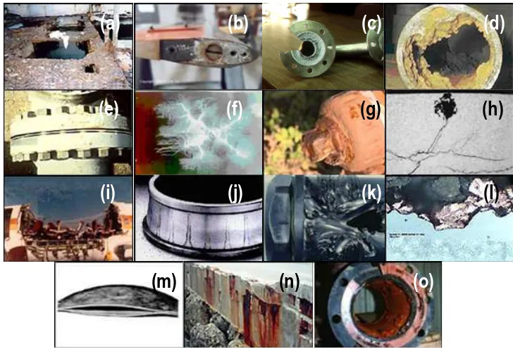
There are several forms of corrosion, also referred as modes or mechanisms of corrosion. Although they can be described using different terminologies, the one given here being among the most accepted. Although McKay and Worthington proposed eight forms of corrosion in their seminal 1936 book,[7] around fifteen different forms are currently found in
the literature:[8-10]
a) Uniform corrosion. The surface effect produced by most direct chemical
b) Galvanic corrosion. This is an electrochemical action of two dissimilar metals in presence of an electrolyte and an electron conductive path. It occurs when dissimilar metals are in contact (Fig. 1.1b).
c) Concentration cell corrosion. This occurs when two or more areas of a metal surface are in contact with different concentrations of the same solution (Fig. 1.1c).
d) Pitting corrosion. This localized corrosion occurs at microscopic defects on a metal surface. The pits are often found underneath surface deposits caused by corrosion product accumulation (Fig. 1.1d).
e) Crevice corrosion. This corrosion, which is also named contact corrosion, is produced at the region of contact of metals with metals or metals with non-metals. It may occurs at washers under barnacles, at sand grains, under applied protective films, and at pockets formed by threaded joints (Fig. 1.1e).
f) Filiform corrosion. This occurs on painted or plated surfaces when moisture
permeates the coating. Long branching filaments of corrosion product extend out from the original corrosion pit and cause degradation of the protective coating (Fig. 1.1f).
g) Intergranular corrosion. This is an attachment on or adjacent to the grain boundaries of a metal or alloy (Fig. 1.1g).
h) Stress corrosion cracking. This is caused by the simultaneous effects of tensile stress and specific corrosive environment (Fig. 1.1h). Stresses may be due to applied loads, residual stresses from the manufacturing process, or a combination of both.
i) Corrosion fatigue. This is a special case of stress corrosion caused by the combined effects of cyclic stress and corrosion (Fig. 1.1i). No metal is immune from some reduction of its resistance to cyclic stressing if the metal is in a corrosive environment.
j) Fretting corrosion. This refers to corrosion damage at the asperities of contact
(a)
(b)
(c)
(d)
(e)
(f)
(g)
(h)
(i)
(j)
(k)
(l)
[image:20.499.72.436.69.317.2](m)
(n)
(o)
Figure 1.1. Examples to illustrate the different types of corrosion.
k) Erosion corrosion. This is the result of a combination of an aggressive chemical
environment and high fluid-surface velocities (Fig. 1.1k).
l) Dealloying. This is a rare form of corrosion found in copper alloys, gray cast iron, and some other alloys. Dealloying occurs when the alloy loses the active component of the metal and retains the more resistant component in a porous “sponge” on the metal surface (Fig. 1.1l).
m) Hydrogen damage. Hydrogen embrittlement is a problem with high-strength steels, titanium, and some other metals (Fig. 1.1m). Control is by eliminating hydrogen from the environment or by the use of resistant alloys.
o) Microbial corrosion. This corrosion is caused by the presence and activities of microbes (Fig. 1.1o). It can take many forms and can be controlled by biocides or by conventional corrosion control methods.
1.2.
Corrosion prevention
Corrosion prevention aims at removing or reducing the effect of one or more of the conditions leading to corrosion using the following measures:
(1) Appropriate materials selection (2) Change of environment (3) Suitable design
(4) Electrochemical protection (i.e. cathodic and anodic protection) (5) Application of coatings
The choice between these possibilities is usually based upon economic considerations, but in many cases aspects such as appearance, environment and safety must also be taken care of. Two or more of the five principles are commonly used at the same time. It is important to decide upon corrosion prevention at the design stage.
1.2.1.
Materials selection
When selecting materials, each component must be considered with respect to design, manufacture and its effect on the total geometry.[11] However, it is also important that the
grades of structural materials have to be specified, but also the surface treatment and coatings.
The corrosion properties and other functional properties of materials depend on several external factors such as geometry, manufacture, surface conditions, environmental factors and mechanical load conditions. For each functional property these factors have to be evaluated. The final materials selection is often a result of compromises between various properties and their dependence on external factors.
The best tools for weighing the various aspects are quantitative expressions of properties and performance data valid under various conditions, such as corrosion rate and distribution, lifetime in corrosion fatigue, mechanical or electrochemical threshold values, compared with corresponding quantified requirements or service conditions (i.e. specified lifetime, actual stress intensity factors and functions, and corrosion potential).[8]
Environment Material
Nitric acid Stainless steels
Caustic solutons Nickel and nickel alloys Non-staining atmospheric exposure Aluminium
Distilled water Tin
Hot, strongly oxidizing solutions Titanium
[image:22.499.85.401.331.461.2]Concentrated sulfuric acid Steel
Table 1.1. Some natural combinations of environment and material.[12]
when it contains the smallest possible amounts of impurities. Some “natural” combinations of environment and material are listed in Table 1.1.[12] In several cases, non-metallic
materials such as polymers, rubbers, ceramics, wood or concrete must also be taken into consideration.
1.2.2.
Change of environment
The environment may be changed in the following ways in order to reduce corrosion rates:
a) Decreasing (or increasing) the temperature. b) Decreasing (or increasing) the flow velocity.
c) Decreasing (or increasing) the content of oxygen or aggressive species. d) Adding inhibitors.
Regarding to the first three items, it should be emphasized that corrosion rates most often are reduced by reducing temperature, flow rates, or content of oxygen or aggressive species. On the other hand, the inhibitors can be arranged in groups based on which reaction (anodic or cathodic) they affect and how they influence upon the polarisation properties.
The passivating inhibitors, also called passivators, are usually inorganic. The oxidizing ones act by depolarizing the cathodic reaction (making it more efficient), or more frequently by introducing an additional cathodic reaction. When the concentration of inhibitor becomes high enough (higher than a critical value c), the cathodic current density at the primary passivation potential becomes higher than the critical anodic current density, and consequently the metal is passivated. However, if the inhibitor concentration is below the critical value, it is worse than no inhibitor at all. Examples of oxidizing inhibitors are chromates and nitrites.
N2H4 + O2 N2 + 2H2O (1.5)
2Na2SO3 + O22Na2SO4 (1.6)
These inhibitors are effective in all environments where the oxygen reduction is the dominating cathodic reaction in the uninhibited state, such as in neutral natural waters. Conversely, other types must be used in strongly acid solutions. Vapour phase inhibitors can also be considered as adsorption inhibitors. These are used for protection of wrapped components temporarily. The inhibitor is placed together with the component(s) and acts due to its suitable low saturation pressure, leading to a sufficiently durable inhibitor condensate on the metal surface. By this, the effect of water and oxygen is prevented. It should be emphasized that these inhibitors may accelerate corrosion on some non-ferrous metals and alloys.
A large number of inhibitors for various metals and environments and their behaviour under different conditions are thoroughly dealt with in the literature.[11,13,14] Inhibitors are very
important for corrosion prevention in oil and gas production plants, and in recirculation systems.
1.2.3.
Suitable design
Design and materials selection are performed in connection with each other. In these processes the individual components, the interactions between them and the relation to other structures and the surroundings have to be taken into account. The various phases of the life cycle of the construction (i.e. manufacturing, storing, transport, installation, operation and service, maintenance, and destruction) should be considered. Some important general guidelines are:[15]
1. Design with sufficient corrosion allowance. Pipes, tanks, containers and other equipment are often made with a wall thickness twice the corrosion depth expected during the desired lifetime.
3. For structures exposed to the atmosphere: the design should allow easy drainage with ample supply of air. Alternatively, the opposite: hinder air transport to cavities by complete sealing. For components immersed in aqueous solutions there are similar extremes: efficient aeration should be secured (when this will cause passivation), or aeration should be prevented as far as possible.
4. Design in a way that makes drainage, inspection and cleaning easy.
5. Take the surroundings into account: make arrangements for minimizing the consequences of corrosion (e.g. where it may cause leakage).
6. Avoid high corrosion risk on load-bearing parts or on critical places by shifting the attack to less critical places.
7. Aim at simple geometry, and avoid heterogeneity and sharp changes in the system.
Detailed explanation of these and many other precautions are provided in reference 15.
1.2.4.
Cathodic protection
The main principle of cathodic protection is to impress an external current on the material, which forces the electrode potential down to the immune region, or, for protection against localized corrosion, below a protection potential.[16] In other words, the material is
made the cathode in an electrochemical cell. The external current can be produced in two different ways (Figure 1.2.):
a) By means of a less noble material in the form of sacrificial anodes, which are connected by metallic conductors to the structure to be protected.
b) By means of an external current source, usually a rectifier. A reference electrode may be used to control the rectifier potentiostatically.
been applied in combination with a coating, with the intention to protect the steel on damaged areas of the coating. In recent decades the application of this technology has increased considerably in connection with the expanding offshore oil and gas exploration and production.[16]
Figure 1.2. Cathodic protection by (a) sacrificial anodes and (b) impressed current.
1.2.5.
Anodic protection
Anodic protection can be applied on materials with a well-defined and reliable passive region and low passive current density. The material is polarized in the anodic direction so that the potential is lifted to the passive region.[16] Figure 1.3 shows in principle the
arrangement for internal protection of a steel tank by means of a potentiostat.
Anodic protection is used on objects such as steel tanks for storing and transport of sulphuric acid, apparatus made of stainless steels and titanium for treatment of various acids and salt solutions, and for aluminium exposed to water at high temperature. The method cannot be used in aggressive liquids that may cause localized corrosion or high passive current density. It may be used on 18/8 CrNi stainless steel exposed to 30 % H2SO4 + 1 % NaCl and on titanium exposed to hydrochloric acid solutions.[15] Pitting
is avoided, in the former case because the sulphate ions counteract the chloride, in the latter case because the pitting potentials of titanium in the actual solutions are very high.
Figure 1.3. Internal anodic protection of a steel tank.
Anodic protection might be utilized much more than it has been so far, but the method must not be used under unfavourable conditions, because the anodic polarisation may cause a strong increase of the corrosion rate.
1.2.6.
Corrosion protection by coating
Through the application of coatings, corrosion is prevented by one of the following three main mechanisms or by combination of two of them:
(i) Barrier effect, where any contact between the corrosive medium and the metallic material is prevented.
(ii) Cathodic protection, where the coating material acts as a sacrificial anode.
(iii) Inhibition/passivation, including cases of anodic protection.
1.2.6.1. Metallic coatings
In most cases of corrosion protection by metallic coatings, the purpose is to protect unalloyed or low-alloy steel, but there also exist many cases of other metals to be protected this way.[17] Metallic coatings can be divided in two groups: the cathodic coatings, which are
substrate (i.e. the coatings that have, respectively, a higher and a lower corrosion potential than the substrate in the environment in question). The cathodic coatings will most often act by the barrier effect only, but for some combinations of substrate and environment the substrate can also be anodically protected (on uncovered spots).[17] The anodic coatings, in
addition to the barrier effect, will provide cathodic protection of possible “holidays” (i.e. spots or parts of the surface where the coating is imperfect and the substrate is exposed to the corrosive environment).[17] The normal major difference between a cathodic and an anodic
[image:28.499.74.430.412.469.2]coating is just the behavior at such a defect. This is illustrated in Figure 1.4. In the case of a cathodic coating (Figure 1.4a) the substrate is subject to galvanic corrosion in the coating defect. The corrosion may be rather intensive because the area ratio between the cathodic coating and the anodic spot of bare substrate usually is very high. In the other case (Figure 1.4b), only a cathodic reaction occurs on the bare substrate (it is protected cathodically), while the coating is subject to a corresponding galvanic corrosion distributed over a larger surface area. In order to protect the substrate, low porosity, high mechanical strength and continuous adhesion are even more necessary for a cathodic than for an anodic coating. Some examples of metallic coatings for steel are Ag, Ni, Cr and Pb, which are cathodic, while Zn and Cd are anodic in most environments.[17]
Figure 1.4. Localization of corrosion at a defect in a metal coating on steel: (a) cathodic and (b) anodic coatings.
1.2.6.2. Paint coatings
The use of paint coatings is the most common method for corrosion prevention. An anticorrosive paint is composed of a binder, pigments, a solvent/diluent, extenders and a variable number of other additives such as antioxidants, surface-active agents, driers, thickeners and antisettling agents.[16] A paint is primarily characterized by its pigment or by
its binder. We distinguish between primers, which usually contain pigments causing some
inhibition or cathodic protection of the substrate, and paints for finishing coats, which contain colour pigments and extenders, which may improve the barrier effect of the coating system. The coats in thicker paint systems may be divided into primer, intermediate or body coats and topcoat. Recent development of thick film paints implies less need for distinction between intermediate coats and topcoat. An actual inhibiting type of pigment in primers is zinc phosphate,[16,18] while red lead and zinc chromate, which were earlier in widespread
use, are seldom applied nowadays because of the risk of health injuries. Metallic zinc powders provide cathodic protection of the substrate if the zinc concentration is high enough. The pigments in the finishing coats provide colour and protect the binder from being damaged by ultraviolet sunlight. The most efficient barrier-acting pigment consists of aluminium flakes. The aluminium flakes increase the length of the diffusion path and are therefore assumed to increase the resistance to diffusion of water, oxygen and ions, but more recent investigations have shown that the effect and the mechanism depend strongly upon the type of binder. Other commonly used pigments in intermediate coats and topcoats are various forms of iron oxide. The binder may, for instance be bitumen (coal tar or asphalt), or linseed oil (natural materials), alkyd, chlorinated rubber, epoxy, vinyl, polyurethane etc. (synthetic organic materials), or silicate (inorganic). Some paints are hardened by reaction with oxygen in the air (oil and alkyd paints), others by evaporation of the solvent (e.g. chlorinated rubber) and a third group by a chemical reaction between two components (epoxy and polyurethane paints). Recently, a binder of polysiloxine has been introduced. There is also a growing interest for application of water-based paints (e.g. in marine environments).
The main rule for painting previously painted steel is to use the same type of paint. If the old paint coating has turned out to be unsuitable in the actual environment, it should be removed before the structure is coated with a different type of paint. The cost of the paint itself forms often 15-20 % of the total cost of the painting operations including pre-treatment and application. It is important that the pretreatment and the type of paint are compatible. The advanced paints depend upon good pre-treatment to obtain the necessary adhesion to the substrate.[18]
A suitable film thickness and appropriate periods between application of the successive coats are important, but depend upon the type of paint. Data sheets from the paint producers give information about this. The thickness should be checked during the painting work. Other important properties are adhesion between old and new paint as well as resistance to detergents and mechanical wear. It can be mentioned that hardened two-component paints may be less suitable for over painting unless they are rubbed mechanically, but on the other hand they are resistant to detergents and mechanical wear.[18]
For barrier coatings, the resistance to transport of water, ions and oxygen is of crucial significance for protection of the substrate, and transport and absorption of these substances are also important factors in the deterioration of the coating.[19] The film
resistance and the potential determine the cathodic reaction rate underneath the paint coating,[20] which interacts closely with two of the main deterioration mechanisms, namely
blistering and cathodic disbanding.[21] A good barrier coating is generally characterized by
low uptake of water, low conductivity, and low permeability of water and oxygen, but these properties do not give a direct expression of the durability of the coating.
1.2.6.3. Delamination of painted metals
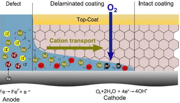
environment may reach the bare metal surface and initiate the corrosion process. The mechanism of the corrosion in the defect is the same that in the case of uncoated metal. However, further progress of the corrosion leads to the delamination of the coating and the consequent detachment of the coating from the metal surface. This usually occurs through one of the following two general mechanisms: cathodic and anodic delamination.
[image:31.499.115.417.281.454.2]The cathodic delamination occurs on ferrous metals and other alloys features conductive passive layers that are directly coated with organic coatings. The process leads to the breakage of the linking between the metal surface and the coating, inducing the loss of the protective properties of the coating. Cathodic delamination leads to the creation of blisters or to flanking off the paint from the metal surface.
Figure 1.5. Scheme of the mechanism for cathodic delamination.
The electrochemical mechanism describing the cathodic delamination of coated steel was reported by Stratmann and co-workers,[22,23] and is illustrated in Figure 1.5. Coating
solution is locally decreased while at cathodic sites it becomes alkaline. The detachment of the coating is caused by the cathodic reaction at the interface. Due to the oxygen reduction, radicals are created. The aggressive species attack and destroy the polymer structure, causing a decrease of its adhesion. The reaction is accompanied by a migration of cations from defects to the cathodic sites. For a weak interface, the migration of ions determines the rate of delaminating process.[23]
Anodic delamination starts in a similar way. At defects local electrodes are created and separated. However, the detachment of the paint is caused by the dissolution of the substrate, which leads to the creation of thin crevices along the metal/polymer interfaces.
1.3.
Conducting polymers for corrosion protection
1.3.1.
Introduction to conducting polymers
Since the discovery of intrinsically CPs in the late 1970 by Heeger, MacDiarmid and Shirakawa, for which they were awarded with the Nobel prize,[24-26] the unique combination of
physical and chemical properties of these materials has drawn the attention of scientists and engineers from many different fields or research. The major feature which made CPs so promising is that they are organic materials with both electronic and electrochemical properties.[27] Among the many technological possibilities of CPs, some examples that
deserve consideration are their application as conductometric transducers to measure changes in enzymatic conversion,[28,29] electroluminescent light emitting diodes,[30,31]
actuators for biomimetic propulsions,[32] nanometric and micrometric supercapacitors,[33,34]
bioactive matrices for tissue engineering [35,36] and electrobactericide films.[37]
Polyacetylene (PA) was the first CP discovered in 1970’s. In the reduced state this polymer shows only semiconducting properties but after treatment in iodine vapour, its conductivity increases by more than fifteen orders of magnitude and reach a value in the range of 104-106 S/cm, which is comparable to that of metals.[38] Spectroscopic
the polymer matrix, the above reaction is accompanied by a simultaneous incorporation of anions into the polymer matrix. However, application of this polymer meets serious difficulties due to its very low stability when exposed to air, its conductivity decreasing very rapidly because of the destruction of the conjugated structure. Although some strategies to improve the stability of PA have been proposed,[39] the low durability still remains a
significant disadvantage of this CP.
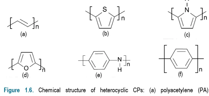
Due to extensive research in the area of CPs, another group of materials was discovered. Heterocyclic CPs: polypyrrole (PPy), polyfuran and polythiophene (PTh) can be easily prepared by electrochemical or chemical oxidation of pyrrole,[27] furane[40] and
tiophene,[41,42] respectively. Also, other aromatic systems such as aniline[43] and azulene,[44]
were found to undergo a polymerisation resulting in a CP [i.e. polyaniline (PAni) and polyazulene, respectively]. The chemical structure of the most representative heterocyclic CPs is depicted in Figure 1.6.
Figure 1.6. Chemical structure of heterocyclic CPs: (a) polyacetylene (PA); (b) polythiophene (PTh); (c) polypyrrole (PPy); (d) polyfurane; (e) polyaniline (PAni); and (f) poly(p-phenylene).
1.3.2.
Electronic structure of conducting polymers
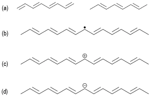
PA has been taken as an example to illustrate fundamentals of electronic structure of CPs, because of its simplicity. The PA chain consists of single and double bonds that are situated in an alternated sequence. Figure 1.7a shows the degenerated ground state of PA.
(a) (b) (c)
[image:33.499.82.441.338.503.2]When the two structures coexist in a single polymer chain, a defect called “soliton” results where the two structures meet (Figure 1.7b). This defect consists of a single unpaired electron with overall charge equals to zero. By controlled addition of p-doping anions which consume free electrons, the neutral soliton transforms into a positive soliton (Figure 1.7c). In contrast, the n-doping of PA results in a negative soliton (Figure 1.7d). Both positive and negative solitons are stable because the charge spreads over several monomer units.[45]
[image:34.499.111.364.356.522.2]Solitons may move along the polymer chain by successive alternation of neighbor single bonds. Solitons may exchange electrons between neighbor chains according to “intersoliton hoping” mechanism. Two neutral solitons which are present in a single chain may recombine, which results in the elimination of defects in the chain. A charged soliton together with a neutral one can form an energetically preferred state called polaron. Chemically a polaron can be considered a radical cation. Polarons may also recombine to create a bipolaron, which is a double charged defect. Polarons and bipolarons are delocalized over several monomer units.
Figure 1.7. (a) Degenerated states of polyacetylene with reversed order of alternated bonds; (b) neutral soliton; (c) positive soliton; and (d) negative soliton.
(a)
(b)
(c)
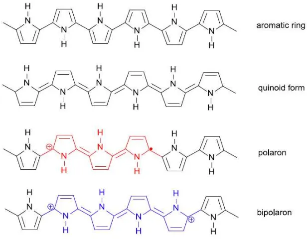
Figure 1.8. Forms of the polypyrrole chain.
Heterocyclic CPs do not have a degenerated state. In the reduced form, they exist as chain of aromatic rings connected by long bonds (Figure 1.8). Another form showing an alternated bond sequence is the quinoid one, in which aromatic rings are connected by double bonds. However, this form is unstable and immediately transforms into the aromatic one. In such structure, formation of two single polarons is not energetically favourable and, therefore, polaron defects are created. At sufficiently high doping levels the polarons recombine into bipolarons.
1.3.3.
Inhibition of corrosion by conducting polymers
CPs as materials which have already showed some anticorrosion behavior became a natural candidate for further research. The models usually employed to describe the corrosion protection imparted by CPs are essentially three:
oxidation of the free metal surface at small defects in the passive layer. However, some works report that this mechanism only applies in chloride free solutions.[46,47] Wessling
claimed that ennobling mechanism also improves the passivity of the oxide layer at the polymer/metal interface, inhibiting electrochemically driven delamination.[48] However, this
effect has been found to be negligible.[49]
2) An alternative mechanism is that, the electrons produced during the metal oxidation at the defect area can go into the polymer and dislocate the oxygen reduction process from the metal/polymer interface. This would hinder the coating detachment caused by interfacial oxygen radicals.[50,51]
3) The self-healing mechanism proposed by Kendig[52] is based on the assumption that
doping anions with corrosion inhibiting properties inside the polymer matrix are released during the reduction of the polymer and migrate to the corresponding defect. Thus, the inhibitor anion could significantly decrease the corrosion rate and the CP would act as a store for corrosion inhibitors, which supplies them immediately just after the corrosion defect appears. The efficacy of the inhibition is strongly dependent of the concentration of doping anions.
These mechanisms are based on the unique properties of CPs. Furthermore, all these mechanisms can contribute simultaneously to the substrate protection. It should be emphasized that many properties of CPs, such as the ionic and electronic conductivity, type and concentration of doping anion, etc., can be controlled during the polymerisation process. Thus, it is possible to adjust the properties of the coating as required by each mechanism, even though it is a serious danger that some of the properties demanded by a given mechanism are unwanted for the other/s.
In recent years the IMEM group of the Universitat Politécnica de Catalunya has investigated the influence of different CPs (i.e. PTh,[53,54,56,58,59] PPy[54,56,57,59] and PAni[55-59]
formulation of the paint, the level of dispersion of the CP in the paint, etc, were examined. Results showed that, in general, the incorporation of CP produces a benefit in the performance of the coating, even though other important conclusions were reached from such studies. More specifically, the improvement achieved for epoxy paints was higher than that obtained for alkyd and polyurethane formulations. In general, the corrosion inhibition induced by PTh derivatives and PAni was higher than that of PPy derivatives. The interval of effective concentrations for the CP was found to range from 0.3 % w/w to 1.0 % w/w. Furthermore, it was found that, in order to the take the maximum profit of the CP as corrosion inhibitor, it is essential to achieve a good dispersion of the additive in the paint. This is usually achieved by incorporating the CP dispersed in an organic solvent (e.g. xylene) into the paint during its formulation. In addition, corrosion tests evidenced that some PTh derivatives and PAni act not only as corrosion inhibitors but also as adhesion promoters.
1.4.
References
[1] F. L. LaQue, "Marine corrosion and prevention", p. 116, John Wiley and Sons, Inc., New York, 1975.
[2] D. B. Anderson and R. W. Ross Jr., "Protection of steel piling in marine splash and spray zone-Metallic sheathing concept", Proceeding of the 4th International Congress on Marine Corrosion and Fouling, France, 461-473, 1976.
[3] T. Hodgkies and S. Rigas, “A comparison of the corrosion resistance of some higher-alloy stainless steels in seawater at 20-100 °C”, Desalination, 1983, 44, 283-294.
[4] D. A. ShiXer, “Understanding material interactions in marine environments to promote extended structural life”, Corros. Sci., 2005, 47,2335-2352.
[5] U. R. Evans, “Electrochemical mechanism of atmospheric rusting”, Nature, 1965, 206, 980-982.
[6] N.-G. Vannerberg and T. Sydberger, “Reaction between SO2 and wet metal
[7] R. J. McKay and R. Worthington, “Corrosion resistance of metals and alloys”, Reinhold Publishing, New York, 1936.
[8] H. H. Uhlig, “Corrosion and corrosion control”, Jon Wiley and Sons, Inc., New York, 1936.
[9] C. P. Dillon, “Forms of corrosion recognition and prevention” (Nace Handbook 1), N A C E International, Houston, 1982.
[10] P. E. Schwitzer and P. A. Schwitzer, “Encyclopedia of corrosion technology”, CRC Press, New York, 2004.
[11] P. R. Roberge, “Handbook of corrosion engineering”, McGraw-Hill, New York, 1999. [12] M. G. Fontana and N. D. Green, “Corrosion engineering”, McGraw-Hill, New York, 1986.
[13] Corrosion Inhibitors, Book B559, EFC 11. London: Institute of Materials, 1994. [14] L. L. Shreir, R. A. Jarman and G. T. Burstein, “Corrosion” Vol. 1, 3rd Ed. Oxford: Butterworth-Heinemann, 1994.
[15] V. R. Pludek, “Design and corrosion control”, The MacMillian Press, 1977. [16] E. Bardal, “Corrosion and protection”, Springer-Verlag, London 2004.
[17] L. L. Sheir, R. A. Jaman and G. T. Burnstein, “Corrosion”, Vol. 2, 3rd Ed., Oxford: Butterworth.
[18] ISO-Standard 12944 – 2, 1988. Paint and varnishes. Corrosion protection of steel structures by protective paint systems. Part 2, 1998.
[19] M. Stratmann, R. Feser and A. Leng, “Corrosion protection by organic films”, Electrochim. Acta, 1994, 39, 1207-1214.
[20] U. Steinsmo and E. Bardal, “Factors limiting the cathodic current on painted steel”, J. Electrochem. Soc., 1989, 136, 3588-3594.
[21] O. Knudsen and U. Steinsmo, “Effect of cathodic disbonding and blistering on current demand for cathodic protection of coated steel”, Corrosion, 2000, 56, 256-264.
[23] A. Leng, H. Streckel and M. Stratmann, “The delamination of polymeric coatings from steel. Part 2: First stage of delamination, effect of type and concentration of cations on delamination chemical analysis”, Corr. Sci., 1998, 41, 579-597.
[24] A. J. Heeger, “Nobel Lecture: Semiconducting and metallic polymers. The fourth generation of polymeric materials”, Rev. Mod. Phys., 2001, 73, 681-700.
[25] A. G. MacDiarmid, “Nobel Lecture: “Synthetic metals”: A novel role for organic polymers”, Rev. Mod. Phys., 2001, 73, 701-712.
[26] H. Shirakawa, “Nobel Lecture: The discovery of polyacetylene film – the dawning of an era of conducting polymers”, Rev. Mod. Phys., 2001, 73, 713-718.
[27] T. A. Skoteheim and J. R. Reynolds “Handbook of conducting polymers”, 3rd edition, CRC Press, Boca Raton, 2007.
[28] S. Geetha, R. K. Chepuri, M. Rao, D. C. Vijayan and D. C. Trivedi, “Biosensing and drug delivery by polypyrrole”, Anal. Chim. Acta, 2006, 568, 119-125.
[29] A. Malinauskas, R. Garjonyté, R. Mazeikiene and I. Jurevieiute, R. K. Chepuri, M. Rao, D. C. Vijayan, D. C. Trivedi, “Electrochemical response of ascorbic acid and electrogenerated polymer modified electrodes for electroanalytical applications”, Talanta, 2004, 64, 121-129.
[30] J. H. Burroughes, D. D. C. Bradley, A. R. Brown, R. N. Marks, K. Mackay, R. H. Friend, P. L. Burns and A. B. Holmes, “Light-emitting diodes based on conjugated polymers”, Nature, 1990, 347, 539-541.
[31] D. Braun, “Semiconducting polymer LEDs”, Mater. Today, 2000, 5, 33-39.
[32] T. F. Otero and M. T. Cortés, “Artificial mucles with tactile sensitivity”, Adv. Mater., 2003, 15, 279-282.
[33] D. Aradilla, F. Estrany and C. Alemán, “Symmetric supercapacitors based on multilayers of conducting polymers”, J. Phys. Chem. C, 2011, 115, 8430-8438.
[34] D. Aradilla, F. Estrany, E. Armelin and C. Alemán, “Ultraporous poly(3,4-ethylenedioxythiophene) for nanometric electrochemical supercapacitor, Thin Solid Films, 2012, 520, 4402-4409.
“Biodegradable free-standing nanomembranes of conducting polymer:polyester blends as bioactive platforms for tissue engineering”, J. Mater. Chem., 2012, 22, 585-594.
[36] L. J. del Valle, F. Estrany, E. Armelin, R. Oliver and C. Alemán, “Cellular adhesión, proliferation and viability on conducting polymer substrates”, Macromol. Biosci., 2008, 8, 1144-1151.
[37] B. Teixeira-Dias, L. J. del Valle, D. Aradilla, F. Estrany and C. Alemán, “A conducting polymer/protein composite with bactericidal properties”, Macromol. Mater. Eng., 2012, 297, 427-436.
[38] M. Nechtstein, F. Devreux, R. L. Greene, T. C. Clarke and G. B. Street, ”One-dimensional spin diffusion in polyacetylene, (CH)x”, Phys. Rev. Lett., 1980, 44, 356-359.
[39] H.Naarman, “Electronic properties of conjugated polymers”, Springer series in Solid State Sciences, Vol. 76, 1987, p. 12.
[40] G. Tourillon and F. Garnier, “New electrochemically generated organic conducting polymers”, J. Electroanal. Chem., 1982, 135, 173-178.
[41] R. J. Waltman, J. Bargon and A. F. Diaz, “Electrochemical studies of some conducting polythiophene films”, J. Phys. Chem., 1983, 87, 1459-1463.
[42] T. Yamamoto, K. Sanechika and A. Yamamoto, “Preparation of thermostable and electric-conducting poly(2,5-thienylene)”, J. Polym. Sci., Polym. Lett. Ed., 1980, 18, 9-12.
[43] E. Genoes and C. Tsintavis, “Redox mechanism and electrochemical behavior of polyaniline deposits”, J. Electroanal. Chem., 1985, 195, 109-128.
[44] A. F. Diaz, J. Castillo, K. K. Kanazawa, J. A. Logan, M. Salmon and O. Fajardo, “Conducting poly-N-alkylpyrrole”, J. Electroanal. Chem., 1982, 133, 233-239.
[45] J. L. Bredas, R. R. Chance and R. Silbey, “Comparative theoretical study of the doping of conjugated polymers: Polarons in polyacetylene and polyparaphenylene”, Phys. Rev., Part B, 1982, 26, 5843-5854.
[46] J. Reuk, A Ópik and K. Idla, “Corrosion behavior of polypyrrole coated mild steel”, Synth. Met., 1999, 102, 1392-1393.
[48] B. Wessling, “Corrosion prevention with an organic metal (polyaniline): Surface ennobling passivation, corrosion test results”, Mater. Corr., 1996, 47, 439-445.
[49] R. J. Holness, G. Williams, D. A. Worsley and H. N. McMurray,”Polianiline inhibition of corrosion-driven organic coating cathodic delamination on iron”, J. Electrochem. Soc., 2005, 152, B73-B81.
[50] P. J. Kinlen, D. C. Silverman and C. R. Jeffereys, “Corrosion protection using polyaniline coating formulations”, Synth. Met., 1997, 85, 1327-1332.
[51] T. D. Nguyyen, M. Keddam and H. Takenouti, “Device to study electrochemistry of iron at a defect of protective coating of electronic conducting polymer”, Electrochem. Solid-State Lett., 2003, 6, B25-B28.
[52] M. Kendig, M. Hon and L. Warren, “Smart corrosion inhibiting coatings”, Prog. Org. Coat., 2003, 47, 183-189.
[53] C. Ocampo, E. Armelin, F. Liesa, C. Alemán, X. Ramis and J. I. Iribarren, “Application of a polythiophene derivative as anticorrosive additive for paints”, Prog. Org. Coat. 2005, 53, 217-224.
[54] J. I. Iribarren, E. Armelin, F. Liesa, J. Casanovas and C. Alemán, “On the use of conducting polymers to improve the resistance against corrosion of paints based on polyurethane”, Mater. Corros., 2006, 57, 683-689.
[55] E. Armelin, C. Ocampo, F. Liesa, J. I. Irribarren, X. Ramis and C. Alemán, “Study of epoxy and alkyd coatings modified with emeraldine base form of polyaniline”, Prog. Org. Coat., 2007, 58, 316-322.
[56] E. Armelin, R. Oliver, F. Liesa, J. Iribarren, F. Estrany and C. Alemán, “Marine paint formulations: Conducting polymers as anticorrosive additives”, Prog. Org. Coat., 2007, 59, 46-52.
[57] E. Armelin, R. Pla, F. Liesa, X. Ramis, J. I. Iribarren, “Corrosion protection with polyaniline and polypyrrole as anticorrosive additives for epoxy paint”, Corros. Sci., 2008, 50, 721-728.
The objectives of this PhD Thesis are the following:
1) Test the performance of nanostructured particles of an electroactive CP as
anticorrosive additive for solvent-borne epoxy formulations. For this purpose, hollow microspheres of poly(N-methylpyrrole) (PNMPy) with a shell thickness of ∼30 nm have been prepared using the layer-by-layer (LbL) self-assembly technique and characterized using different spectroscopic and structural methods. In order to examine the anticorrosive capabilities of these microspheres, a two components epoxy formulation has been prepared by incorporating a very low concentration (0.3-1.0 wt.%) of PNMPy. The compatibility between the PNMPy and the solvent-borne epoxy paint has been investigated by microscopy.
2) Investigate the partial replacement of zinc dust used as anticorrosive additive in
marine epoxy primers by a small concentration of an organic CP. The 79 wt.% of zinc dust of a commercial paint for marine use has been reduced to 60 wt.% without detrimental effects in the protecting properties by adding 0.3 wt.% of polyaniline emeraldine salt (Pani-ES). The purpose of such modification in the paint formulation is to provide important benefits to manufacturers by reducing the health risks, meeting the new regulations and reducing both the formulation cost and paint weight.
3) Extend the use of CPs as anticorrosive additives to alkyd primers, evaluating their
performance by comparison with zinc phosphate. Specifically, zinc phosphate has been replaced in a commercial alkyd primer by PAni-ES, polyaniline emeraldine base (PAni-EB) and poly[2,2’-(3-methylacetate)thiophene] (PTE). The coating adherence, water uptake, permeability and resistance of the commercial and modified primers have been examined after a few hours and 3, 7, and 30 days of immersion in an aggressive NaCl 3.5 wt.% aqueous solution.
4) Evaluate the performance of soluble PTh derivatives as anticorrosive additives of
involve acrylic acid methyl ester and malonic acid dimethyl ester as substitutents at the 3-position of the thiophene ring, have been tested.
A short description of the methods and techniques used to carry out the research tasks is given in this chapter.
3.1.
FTIR spectroscopy
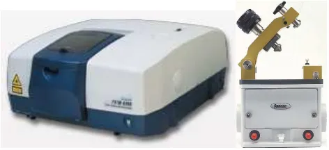
In most cases FTIR spectra were recorded on a FTIR 4100 Jasco spectrophotometer, localized at the Chemical Engineering Department at UPC, with a resolution of 4 cm-1 (transmittance mode) in a wavenumber range of 4000-600 cm-1. Samples were
[image:49.499.148.384.286.394.2]placed in an attenuated total reflection accessory (top-plate) with thermal control and a diamond crystal (Speac-Teknokroma model MKII Golden Gate Heated Single Reflection Diamond ATR).
Figure 3.1. Image of the FTIR spectrometer and reflection accessory used in this work.
Some tests were performed using a Bomem Michelson MB100 FTIR spectrophotometer, from Thermodynamics Department at UPC, with a resolution of 4 cm-1 (absorbance mode) and the same attenuated total reflection accessory.
infrared spectra. Such characteristic makes the FTIR technique a very useful tool for the chemical identification of polymeric materials.
3.2.
Raman spectroscopy
When needed, Raman spectroscopy was performed with a Dilor Jobin Yvon dispersive spectrometer equipped with a 1024 diodes multichannel detector using He/Ne laser (20 mW) with 633 nm of excitation wavelength. The spectral interval ranged from 1200 to 2000 cm-1.
In Raman spectroscopy, a light beam of fixed wavelength (monochromatic light) from a laser source undergoes inelastic scattering as it interacts with the sample material. Inelastic scattering means that the frequency of photons in monochromatic light changes upon interaction with a sample. Photons of the laser light are absorbed by the sample and then re-emitted. The frequency of the reemitted photons is shifted up or down in comparison with original monochromatic frequency, which is called the Raman Effect. This shift provides information about vibrational, rotational and other low frequency transitions in molecules.
3.3.
UV-vis-NIR reflectance spectroscopy
Measurements were performed on a UV/Vis-NIR Shimazu 3600 spectrophotometer, which contains a tungsten halogen visible source, a deuterium arc UV source, a photomultiplier tube UV-Vis detector, and an InGaAs photodiode and cooled PbS photocell NIR detectors. The wavelength range is 185-3300 nm. We worked in the reflectance mode, which was done using the integrating sphere accessory (Model ISR-3100). The interior of the sphere is coated with a highly diffuse BaO reflectance standard. The total reflectance measured by this device will be both specularly reflected and diffusely reflected light. Single-scan spectra were recorded at a Single-scan speed of 60 nm/min using the UVProbe 2.31 software.
In principle the technique is similar to IR spectroscopy, so when a sample of an unknown compound is exposed to light, certain functional groups within the molecule absorb light of different wavelengths in the UV or visible or NIR region. UV-VIS-NIR spectroscopy is used for qualitative and quantitative analysis of materials.
Figure 3.2. UV-vis-NIR spectrophotometer and basic optical layout for a double beam integrating sphere, localized at the Center for Research in NanoEngineering (CRnE-UPC).
3.4.
X-Ray photoelectron spectroscopy
current of the electrons were 4 eV and 0.35 mA, respectively. For the argon gun, the energy and the emission current were 0 eV and 0.1 mA, respectively. The partial pressure for the argon flood gun was 2·10-8 mbar. Data acquisition and processing were achieved with the
Advantage Software. Spectral calibration was determined by setting the main C 1s component at 285 eV. The surface composition was determined using the manufacturer's sensitivity factors.
[image:52.499.62.425.320.466.2]Each element produces a characteristic set of XPS peaks at characteristic binding energy values, enabling the identification of each element existing inside or on the surface of the analyzed material. These characteristic peaks correspond to the electron configuration of the electrons within the atoms, (e.g., 1s, 2s, 2p and 3s) The number of detected electrons in each of the characteristic peaks is directly related to the amount of element within the irradiated area (volume).
Figure 3.3. X-ray photoelectron spectroscopy chamber with a nine channel detector and SPM 150 Aarhus chamber equipped with ultra-high vacuum conditions (<10-10mbar), localized at the Center for Research in NanoEngineering (CRnE-UPC).
3.5.
Scanning electron microscopy and energy dispersive X-ray
spectroscopy
SEM uses a focused beam of high-energy electrons to generate a variety of signals at the surface of solid specimens. Accelerated electrons carry significant amounts of kinetic energy, and this energy is dissipated as a variety of signals produced by electron-sample interactions when the incident electrons are decelerated in the solid sample. These signals include secondary electrons, backscattered electrons, diffracted backscattered electrons, photons, visible light and heat. Secondary electrons and backscattered electrons are commonly used for imaging samples: secondary electrons are most valuable for showing morphology and topography on samples, backscattered electrons are most valuable for illustrating contrasts in composition in multiphase samples (i.e. for rapid phase discrimination) and photon are used for elemental analysis and continuum X-rays.
Figure 3.4. Focused Ion Beam Zeiss Neon 40 scanning electron microscope, localized at the Center for Research in NanoEngineering (CRnE-UPC).
3.6.
Transmission electron microscopy
Figure 3.5. Philips TECNAI 10 electron microscope localized at the Chemical Engineering Department of UPC.
The TEM microscope operates on the same basic principles as the light microscope but uses electrons instead of light. What can be seen with a light microscope is limited by the wavelength of light. TEM uses electrons as light source and their much lower wavelength makes it possible to get a resolution a thousand times better than with a light microscope.
3.7.
Optical Microscopy
The coating surfaces were observed using an Olympus BX-5 light polarizing microscope, operating in reflection mode with an Olympus C3030Z digital camera coupled, localized in the CRnE.
[image:54.499.127.359.67.264.2]There are two types of polarizing microscopes: transmitted light models and incident light models. Figure 3.6 shows the basic construction of a transmitted light polarizing microscope.
Figure 3.6. External view of a transmitted light polarizing microscope (BX-P).
3.8.
Differential Scanning Calorimetry
Differential scanning calorimetry (DSC) was performed using a TA Instruments Q100 series equipped with a refrigerated cooling system (RCS) operating at temperatures from -90 to 550 °C and employing a heating rate of 10 °C/min. Experiments were conducted under a flow of dry nitrogen with a sample weight of approximately 5 mg and calibration was performed with indium.
Figure 3.7. Differential Scanning Calorimeter (TA Instruments Q100), localized at the Chemical Engineering Department of UPC.
3.9.
Thermogravimetry
Thermogravimetric analyses (TGA) were mainly carried out with a Perkin Elmer TGA-6 thermobalance at a heating rate of 10 °C/min under nitrogen atmosphere and a temperature range from 30 to 850 °C. In some occasions TGA were carried out with a Q50 thermogravimetric analyzer of TA Instruments at a heating rate of 20 °C/min under nitrogen atmosphere and a temperature range from 20 to 600 °C.
[image:56.499.176.310.70.226.2] [image:56.499.168.318.428.592.2]TGA is a type of testing that is performed on samples to determine changes in weight in relation to changes in temperature. TGA is commonly employed in research and testing to determine characteristics of materials such as polymers, to determine degradation temperatures, absorbed moisture content of materials, the level of inorganic and organic components in materials and solvent residues.
3.10.
Stress-strain assays
The mechanical properties of the paints were evaluated through stress-strain assays with a Zwick Z2.5/TN1S testing machine. Regular films were prepared by evaporation at room temperature of the volatile organic solvent or by casting and after post-curing. Plate samples with a length of 30 mm and a width of 3 mm were cut out from paint films and used. The deformation rate was 10 mm/min. All the mechanical parameters reported in this work were obtained by averaging the results obtained from ten independent measurements.
This kind of stress-strain assays consist on hold the sample using hydraulic grips and apply a determined deformation rate until breaking in order to determine mechanical characteristics like Young’s modulus, tensile strength and elongation at break.
[image:57.499.198.316.412.579.2]3.11.
Electrochemical Impedance Spectroscopy
EIS was performed as a function of time in aqueous 3.5 wt.% NaCl solution at open circuit potential (EOCP). Stainless steel and platinum electrodes were used as counter electrodes while
the silver|silver chloride (Ag|AgCl) electrode were used as reference electrode in all cases. EIS measurements were performed in potentiostatic mode at the EOCP. The amplitude of the EIS
perturbation signal was 10 mV, the frequency ranged from 105 to 10−2 Hz taking 70 frequencies
[image:58.499.121.365.237.397.2]per decade with a potentiostat Autolab PGSTAT 302N.
Figure 3.10. Potentiostat Autolab PGSTAT 302N, localized at the Chemical Engineering Department of UPC.
Electrochemical systems such as coated surfaces or corroding metals often behave like simple electronic circuits.[1-5] Within the framework of ac waveforms, a few simple circuit
Figure 3.11. The Randles cell equivalent circuit.
When this equivalent circuit model is applied to a coating immersed in an electrolyte, R1 represents the resistance of the electrolyte solution between the reference electrode tip and the surface of the coating. The value of R1 is usually a few ohms if the concentration of electrolyte’s salt is small. The capacitor, C, represents the coating and can be characterized by the thickness and dielectric constant of the coating material. Finally, the resistor, R2, corresponds to the resistance of the coating. It is also a property of the material of the coating and varies with the thickness and composition of the coating.
The same equivalent circuit can also be applied to a bare corroded metal in an electrolyte solution. Once again R1 is associated with the electrolyte resistance. However, in such system the capacitor, C, is associated with the double layer capacitance (Cdl) of the
metal/electrolyte interface. The value of C is generally between 10 and 100 µF/cm2. In
system the resistor R2 is related with the polarisation resistance.
3.12.
Accelerated Corrosion Assays
Corrosion studies were performed using the home-made equipment (Figure 3.12) developed and patented in our laboratory.[6] This device is prepared to perform accelerated
immersion assays in an aggressive solution medium, which consists of an aqueous solution of NaCl (3.5 wt.%, pH=6.6) or NaHSO3 (3 wt.%, pH=3.5) stored in a plastic or glass
![Table 1.1. Some natural combinations of environment and material.[12]](https://thumb-us.123doks.com/thumbv2/123dok_es/5309142.98352/22.499.85.401.331.461/table-natural-combinations-environment-material.webp)