UNIVERSIDAD DE VALLADOLID
ESCUELA DE INGENIERIAS INDUSTRIALES
Grado en Ingeniería Mecánica
Diseño e implementación de un sistema
fotovoltaico en “The Moving Lab”
Autor:
Posadas Muñoz, Pablo
Responsable de Intercambio en la Uva:
García Ruiz, Fco. Javier
Valladolid, mes y año.
TFG REALIZADO EN PROGRAMA DE INTERCAMBIOTÍTULO: Design and implementation of a solar power system in The Moving Lab
ALUMNO: Posadas Muñoz, Pablo
FECHA: 21 de Junio de 2018
CENTRO: University Colleges of Leuven – Limburg
Resumen
Este documento describe el diseño e implementación de un sistema de energía solar en un laboratorio móvil conocido como "The moving lab". El objetivo consistía en satisfacer cualquier necesidad energética de dicho laboratorio con el fin de hacerlo autosuficiente. La potencia se deriva de seis paneles solares de 300 W cada uno colocados en el remolque, a su vez el despliegue de los mismo se realiza de forma automática. Mi objetivo en el proyecto del sistema de energía solar se centró en el diseño mecánico. Debido a las dimensiones del remolque, de más de 2 metros de altura, uno de los principales problemas fue alcanzar el techo para colocar tantos paneles solares como fuera posible y encontrar una manera de desplegarlos sin intervención humana. Se ha utilizado el software Inventor para resolver estos problemas antes de comenzar a construir. Finalmente, después del diseño por ordenador, participé en la construcción del conjunto.
Management and Technology Group
Design and implementacion of a solar power
system in The Moving Lab and design of an air
quality device
University Colleges of Leuven-Limburg Final Degree Project of Electromechanics
Author:
Pablo Posadas Muñoz
Promoters:
Mr. Thomas Vanhove Mr. Jan Elsen
Mr. Wim Claes
Exchange Student of University Colleges of Leuven –
Limburg, student number: r0728971, from Universidad de Valladolid, número de estudiante: e12423293
1
Acknowledgements
Dear reader,
My name is Pablo Posadas, author of this project and exchange student from the University of Valladolid (Spain). This is my senior year of Mechanical Engineering and I decided to do my final project abroad.
My European Erasmus+ exchange program has given me a base to broaden my horizons, learn in a different way and challenge myself daily as well as be part of an unforgettable experience. That is why there are many people whom I would like to express my gratitude to.
First of all, in the UCLL I have taken part of the Energy Department, in which I have been able to design and build a project that otherwise would not have been possible to do. I would like to thank the whole department for their help during these months, especially to Thomas Vanhove for leading and guiding me, Jan Elsen for his assistance and help in the design and while building and Eric Dirkx for his lessons and tips in the workshop. I also would like to show my gratitude to my fellows, Dennis Maes and Diedde Briers, who have made my stay in the Energy laboratory as pleasant and enjoyable as possible and helped me daily with my work.
Secondly, my regards to my Erasmus coordinator, Wim Claes, as well as my promoter in Spain, Fco. Javier García Ruiz for their willingness to answer all my questions and provide me with all the information I needed.
Last but not least, I want to say thank you to all the friends whom I have shared this experience with, Erasmus and Belgian. And with those who have supported me from Spain, family and friends.
Cordially,
2
Abstract
This project has been developed at the UC Leuven Limburg, in the Energy Expertise Unit. This group focuses on research, study and transfer of research results to education regarding new energy technologies.
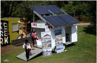
This paper describes the design and the implementation of a solar power system in “The moving lab”. The goal was to power the lab devices as well as any energetic necessity
around it. The power is derived from six 300W solar panels placed on the roof of the trailer which are also extended automatically. A second assignment was the design of an air sensor device able to be attached to a drone or to a street post. Its purpose is to
measure pollution and contamination to be studied in “The moving lab”.
My aim of the solar power system project was focused on the mechanical design. Due to the dimensions of the trailer, more than 2 meters high, one of the biggest problems was to reach the roof to place as many solar panels as possible and find a way to display them without manual intervention. Inventor software has been used to solve these problems before start building.
Concerning the air sensor device, the main task was to design a box that could hold the required sensors, pumps and devices but being as small as possible. Depending on where the box is going to be placed, the features of weight, dimensions, attachment system and sensors required, vary. The adopted solution is to have different designs for each box.
Finally, after designing on the computer I helped making parts at the work shop and put them together. Here I learned to solve daily problems that cannot be seen on the screen before. Regarding the box, the street post design has been 3D printed and finished as well.
Pablo Posadas
3
Resumen
El desarrollo de este proyecto ha tenido lugar en la UC Leuven Limburg, en la Unidad de Energía Avanzada. Este grupo se centra en la investigación, el estudio y la transferencia de los resultados obtenidos a la educación en relación con las nuevas tecnologías energéticas.
Este documento describe el diseño e implementación de un sistema de energía solar en un laboratorio móvil conocido como "The moving lab". El objetivo consistía en satisfacer cualquier necesidad energética de dicho laboratorio con el fin de hacerlo autosuficiente. La potencia se deriva de seis paneles solares de 300 W cada uno colocados en el remolque, a su vez el despliegue de los mismo se realiza de forma automática. Una segunda tarea consistió en diseñar un dispositivo sensor de aire capaz de ser conectado a un dron o a un poste de la calle. Su finalidad es medir la polución y la contaminación de su entorno para posteriormente ser estudiado en " The moving lab ".
Mi objetivo en el proyecto del sistema de energía solar se centró en el diseño mecánico. Debido a las dimensiones del remolque, de más de 2 metros de altura, uno de los principales problemas fue alcanzar el techo para colocar tantos paneles solares como fuera posible y encontrar una manera de desplegarlos sin intervención humana. Se ha utilizado el software Inventor para resolver estos problemas antes de comenzar a construir.
Con respecto al dispositivo sensor de aire, la tarea principal fue diseñar una caja que pudiera contener los sensores, bombas y dispositivos requeridos pero que fuera lo más pequeña posible. Dependiendo de dónde se vaya a colocar la caja, las características de peso, dimensiones, sistema de fijación y sensores necesarios varían. La solución adoptada fue tener diferentes diseños para cada caja.
Finalmente, después del diseño por ordenador, participé en la construcción y montaje del conjunto. Aquí he aprendido a lidiar con los problemas del día a día que no se pueden ver en una pantalla. En cuanto a la caja, el diseño del poste de la calle se realizó con una impresora 3D y se finalizó con éxito.
Pablo Posadas
4 This Final Degree Project has been structured in 8 chapters.
In Chapter 1, "Preliminary Study", the characteristics and main advantages of the construction of a mobile laboratory are presented, as well, the main objectives of the project are identified.
Next, in Chapter 2, "Photovoltaic System", the theoretical framework that determines the design of the solar panel system, is explained. It also includes an introduction to the electrical system.
Subsequently, Chapter 3, "Preliminary Design" describes the stages that the design has followed until the moment of construction, as well as the different problems that we have had to face. In addition, this chapter includes some of the already-done designs that have served as inspiration. The different models that have been developed with the software Autodesk Inventor Professional 2018 are also shown.
In Chapter 4, "Structural description and calculations", the description of each of the parts and components of the design is carried out, as well as a brief introduction to the structural calculations.
In Chapter 5, "Building Process", the stages of the construction process are analysed step by step. A description of the machines and the material used is also added.
In Chapter 6, "The Box", the device for measuring air quality and environmental pollution is presented. Its design is justified, and its characteristics are described.
Finally, in Chapter 7, "Conclusions and references," the conclusions reached after the development of the Thesis are included. In addition, possible lines of study are exposed to deepen the development of future work. The bibliography used is also included.
5
TABLE OF CONTEST
List of figures
List of Tables
CHAPTER l. Preliminary Study
1. Introduction... 11
1.1. The Moving Lab: definition ... 11
1.2. The Moving Lab: applications ... 12
1.3. The Moving Lab: Air Quality Device ... 13
2. Background ... 14
3. Goals ... 14
4. Scope of the project ... 14
CHAPTER ll. Photovoltaic System 1. Solar energy ... 16
1.1. Orientation ... 16
1.2. Tilt ... 17
1.3. Optimum ... 18
2. Solar Trailer System ... 19
2.1. Optimal Layout for the PV panels ... 19
2.2. Calculation of energy produced. ... 20
CHAPTER III. Preliminary Design 1. Design stages ... 21
2. State-of-the-art ... 22
2.1. Solar Trailer ... 22
Example 1 ... 23
Example 2 ... 24
Example 3 ... 25
Example 4 ... 26
2.2. Mobile laboratories ... 27
Example 5 ... 27
Example 6 ... 28
6
3. Problems faced ... 29
3.1. Dimensions of the trailer ... 29
3.2. Trailer’s frame ... 30
3.3. Number of solar panels and layout ... 30
3.4. Unfold system angle ... 31
4. CAD model ... 32
4.1. Software ... 32
4.2. First Design ... 32
4.3. Second Design ... 34
4.4. Final Design ... 36
CHAPTER IV. Structural description 1. Components. ... 38
1.1. Beams ... 38
UNI EN 10056 – L 50 x 50 x 3 ... 38
SOLAR PROFILE 45 x 45 2N180 ... 39
1.2. Bolts and Nuts ... 40
2. The trailer ... 41
3. Frames ... 44
3.1. Trailer Frame ... 44
3.2. Support Frame ... 45
3.2.1. Actuators fulcrum ... 47
3.2.2. Hinges ... 48
3.2.3. Rest points ... 49
3.3. Top Frame ... 49
3.4. Lateral frame ... 51
3.5. Linear actuator ... 53
3.6. Gas springs ... 55
CHAPTER V. Building process 1. Tools and materials ... 56
2. Procedure ... 58
3. Electric assembly ... 61
7
2. Description ... 62
2.1. Sensors ... 63
3. Drone model – Flying Laboratory ... 64
4. Pole model – Air Quality Monitor ... 68
CHAPTER VII. Conclusions and References 1. Conclusions... 69
2. References ... 70
CHAPTER VIII. Annexes
Drawings
8
List of figures
Figure 1. Mobile Laboratory Unit ... 11
Figure 2. Mobile Energy Unit ... 12
Figure 3. Fields of application ... 13
Figure 4. Solar Panel Orientation Factors ... 16
Figure 5. Angle of Orientation for Optimum Isolation in Solar Panels ... 17
Figure 6. Orientation vs. Tilt Comparative Graphic ... 18
Figure 7. Calculation Solar Blog ... 20
Figure 8. Example 1. Solar Trailer Folded………23
Figure 9. Example 1. Solar Trailer Unfolded ... 24
Figure 10. Example 2. GT916 Solar Trailer – GreenTow ... 24
Figure 11- Example 3. TMSPDC – Ok Solar ... 26
Figure 12. Example 4. MREU – UCLL... 27
Figure 13. Example 5. MS-225 SOLAR GENERATOR – Mobile Solar ... 28
Figure 14. Example 6. The SkyFire Energy Solar Energy Station. ... 28
Figure 15. Trailer Frame Front view, Autodesk Inventor ... 30
Figure 16. Actuator Forces Distribution with Low Angle, Autodesk Inventor ... 31
Figure 17. Solar Panels View of the First Design, Autodesk Inventor. ... 33
Figure 18. Sliding guides. ... 33
Figure 19. First actuator design, Autodesk Inventor. ... 34
Figure 20. Previous hinge design in the second design, Autodesk Inventor. ... 35
Figure 21. Previous actuator design in the second design, Autodesk Inventor. ... 35
Figure 22. Right view of the final design, Autodesk Inventor. ... 37
Figure 23. Left view of the final design, Autodesk Inventor. ... 37
Figure 24. UNI EN 10056 – L 50 x 50 x 3 ... 39
Figure 25. SOLAR PROFILE 45 x 45 2N180 ... 39
Figure 26. T-Nuts used in the square profiles. ... 40
Figure 27. Example of the screws used to build The Moving Lab. ... 40
Figure 28. Front view of the trailer... 41
Figure 29. Left view of the trailer. ... 42
Figure 30. Right view of the trailer. ... 42
Figure 31. Back view of the trailer. ... 43
Figure 32. Trailer Frame detail, Autodesk Inventor. ... 44
Figure 33. Trailer Frame top view detail, Autodesk Inventor. ... 45
Figure 34. Support Frame top view detail, Autodesk Inventor. ... 45
Figure 35. Detail of the join system to the trailer, Autodesk Inventor. ... 46
Figure 36. Actuator fulcrum in The Moving Lab. ... 47
Figure 37. Hinges in The Moving Lab ... 48
Figure 38. Rest points in The Moving Lab. ... 49
Figure 39. Detail of the Top Frame, Autodesk Inventor. ... 50
Figure 40. Structural system of the Top Frame, Autodesk Inventor. ... 50
Figure 41. Detail of the Lateral Frame, Autodesk Inventor. ... 51
Figure 42. detail of the lock points in The Moving Lab. ... 52
9
Figure 44. View of the actuator placed in The Moving Lab. ... 54
Figure 45. Detail of the actuator dimensions. ... 54
Figure 46. Dimensions of the gas spring location... 55
Figure 47. Drills used during the construction. ... 56
Figure 48. Detail of the T-Nuts in the beams. ... 57
Figure 49. Automatic Saw, VM Service. ... 57
Figure 50. Drilling Machine, IMA Malilla. ... 58
Figure 51. Aluminium billet for the hinges. ... 58
Figure 52. Construction of the Top Frame detail. ... 59
Figure 53. Construction of the Lateral Panels detail. ... 59
Figure 54. Mounting the Top Frame to the trailer. ... 60
Figure 55. View of the mounting place. ... 60
Figure 56. Raspberry Pi. ... 63
Figure 57. Particle Monitor Sensor, PMS 5003 ... 63
Figure 58. Alphasense B4 serial sensors example. ... 64
Figure 59. Drone M600, Djicdn. ... 65
Figure 60. Inside details of the Flying Laboratory, Autodesk Inventor. ... 66
Figure 61. Detail of the box placed in the drone, Autodesk Inventor. ... 67
10
List of Tables
Table 1. Diepenbeek Campus Location. ... 18
Table 2. Solar Panel Main Characteristics ... 19
Table 3.Monthly Solar Isolation in Diepenbeek Campus ... 19
Table 4. Patriot Solar Group Trailer Mechanical Specifications ... 24
Table 5- GreenTow Trailer Mechanical Specifications. ... 25
Table 6. Ok Solar Trailer Mechanical Specifications ... 25
Table 7. First design features. ... 34
Table 8. Second design features. ... 36
Table 9. final design features. ... 36
11
CHAPTER l. Preliminary Study
1.
Introduction
What are the possible technologies for producing off-grid electricity? Options include fossil fuel-based technologies such as diesel generators, or renewable sources such as photovoltaic or wind power.
And what if we could use one of them to power a mobile research station called The Moving Lab?
In this thesis, I describe the mechanical design and implementation of a 1800W photovoltaic (PV) electric power system in The Moving Lab.
In the following sections I will give a brief description of the technical elements of the project, as well as an overview of the work done during the project and its result.
1.1. The Moving Lab: definition
In the technological advances of the 21st century, science has covered many of the work areas where its usefulness is being of significant importance, appearing a new and revolutionary portable work equipment called Mobile Laboratory, this is a means for the realization of an infinity of projects highly necessary to be able to elaborate many tasks, being able to adapt to the needs of the user.
Mobile laboratories allow access to reliable laboratory services in locations that would otherwise not be able to support full laboratory facilities. It also reduces the time to obtain reliable analytical results, compared to conventional laboratory tests, helping to make quick decisions on the spot in case of an emergency.
12 Another revolutionary advance is the Mobile Energy Unit which is available to provide energy from different kind of sources. This means it can supply energy without being connected to the general grid. As it is mobile, it can be brought to provide energy to the most isolated places, or also it can be used in connected places when a failure occurs in the general grid.
Figure 2. Mobile Energy Unit
Our goal in this project is to integrate the autonomous energy system of the Mobile Energy Unit into our Mobile Laboratory, giving it the ability to be self-sufficient. This would allow us to combine its applications resulting into a wide range of possibilities. That is how the idea of The Moving Lab was born.
1.2. The Moving Lab: applications
The mobile laboratory can be brought to the site, allowing site personnel to interface quickly and directly with laboratory staff. The laboratory offers real-time analytical results for both site investigation and remediation projects, thereby providing the analytical data necessary to make important decisions in the field, to meet project schedules, and to reduce mobilization and equipment costs.
The use of mobile units and laboratories nowadays is essential in situations in which it is required:
• Analysis and monitoring in situ.
• Agility and speed of action.
• Reduction of logistics costs.
13 So, The Moving Lab has application in the following fields:
• Medical equipment
• Emergency Services
• Communications
• Military
• Wild live
• Events and Entertainment
• Educational use
Figure 3. Fields of application
1.3. The Moving Lab: Air Quality Device
Along with the development of The Moving Lab this project includes the design of an air quality measurement device. The purpose of this section of the project is to show some of the possible applications provided by The Moving Lab as well as to open a new alternative line of development with the aim of promoting future projects related to it.
The air quality device consists of a box in which different sensors and electronic devices will be introduced, such as wireless connection or vacuum pumps in order to take measurements of the air in unusual conditions.
Due to the elements that make up the device, the requirements of the box vary and there may be several types of different designs depending on what you want to measure with them and the form of measurement. In this project two possibilities have been studied:
- The first one consists on a box that has integrated sensors, vacuum pumps and measuring tubes. This device is placed on a drone with the objective of taking measurements in locations of difficult access for people.
14 these units around an area affected by a pollution catastrophe would allow us to determine its expansion range.
2.
Background
Currently, the UCLL has already built the Mobile Renewable Energy Unit (MREU) based on solar energy, background of this project and inspirations as well.
We start from the premise that the first designs have been done without knowing how the real trailer dimensions, roof and structure were. That means that initially, this project has been developed with a trailer-to-structure approach. This means that the core design has been focused around the mechanical design of the solar system and integrated into the trailer.
3.
Goals
The goals of this Final Degree Project are those that are represented below:
- Study and understanding of a Mobile Energy Unit with the final purpose of develop The Moving Lab.
- Learning the software tool Autodesk Inventor Professional 2018, which is widely used in today's industry.
- Realization of a simple, resistant and economically affordable structural design of The Moving Lab solar array in order to optimize and facilitate its construction.
- Final construction of The Moving Lab.
- Design of the air quality measurement device as an example of the application of The Moving Lab.
4.
Scope of the project
15 thesis I will speak in the plural since several of the decisions have been made with the help and advice of these colleagues.
This project only focuses on the design of the mechanical part of The Moving Lab, the study and analysis of the electrical components is detailed and deeply studied in the Thesis Work of Diedde Briers.
In this project, no calculations are required. The low weight of the aluminium structure and solar panels, and the low loads required to lift it, make the possible failures due to deformation of the structure, needless.
In addition, the small area covered by the solar panels allows us to disregard the calculations of wind and snow loads. This is also due to the fact that the structure is compact and with several points of support, not like solar installations of a single pole that are more susceptible to this type of loads.
16
CHAPTER ll. Photovoltaic System
In this chapter the photovoltaic system is briefly described. It is an introduction to solar systems design so that can it be explained how the PV array works and why the design was made like that. In this chapter I define the power capacity of The Moving Lab as well as a description of its devices and the requirements of the Photovoltaic System.
1.
Solar energy
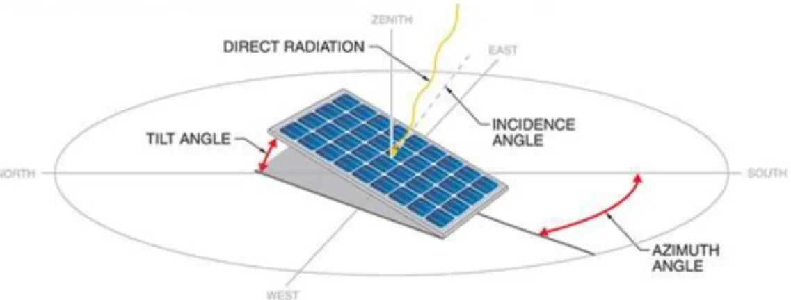
In the Solar Systems design there are two main factors of study. The correct orientation (azimuth angle) and the optimal inclination of the panels (tilt angle) depending on the energy requirement and the geometric location.
Figure 4. Solar Panel Orientation Factors
1.1. Orientation
17
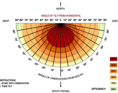
Figure 5. Angle of Orientation for Optimum Isolation in Solar Panels
Since solar panels are more productive when the sun's rays are more perpendicular, the best is the one that is directly to the south, but the tilt or orientation of the PV array does not need to be perfect. Solar modules produce 95% of their full power when within 20° of the sun’s direction. Or even if the trailer’s panels face east or west, it may also be acceptable. This can be seen in the Figure 5.
Also, optimum orientation can be influenced by typical local weather patterns as rain and fog. Thus, in Belgium the maximum power is generated with a southwest orientation.
1.2. Tilt
It depends on two factors:
- Latitude of the geographical location
- Season of the year
An increased tilt favours power output in the winter and a decreased tilt favours output in the summer. Nevertheless, tilts from 20° to 45° will result in approximately the same power production over the course of the year. This is because tilts that are less than the latitude of the site increase summer production when the solar resource is most available here but reduce winter production when it tends to be cloudy anyway.
18
Diepenbeek Campus
Latitude Longitude
50.926 North 5.392 East
50°55'31" North 5°23'32" East
Table 1. Diepenbeek Campus Location.
As shown in the Table 1, following the general rule the optimum would be:
50°55'31" - 15° = 35°55'31"
1.3. Optimum
As can be appreciated in the IMAGE the optimum orientation and angle in fixed arrays is around 30° and 40°.
19 Combining the data obtained in the table with the optimum for the angle of inclination of the panels, we deduce that the optimum angle for our project would be around 35° to the horizontal axis. It can also be said that the inclination is 55° to the vertical axis.
35° is the angle which we are going to work with. The project has finally been designed and built with this angle.
2.
Solar Trailer System
The solar PV generator consist of 6 solar panels from CSUN Solar of 300W each. Therefore, the system has a total power of 1,800W. The main electrical characteristics of the panels are shown in Table 2. The complete datasheet can be found in Annex.
CSUN-300-60M-BB
Voltage (V)
Nominal Power (𝐏𝐌𝐏𝐏) [W]
Max-Power Voltage (𝐕𝐌𝐏𝐏) [V]
Max-Power Current (𝐈𝐌𝐏𝐏) [A]
Open-Circuit Voltage (𝐕𝐎𝐂) [V]
Short-Circuit Current (𝐈𝐒𝐂) [A]
24 300 32.2 9.31 39.8 9.6
Table 2. Solar Panel Main Characteristics
2.1. Optimal Layout for the PV panels
To choose the best layout possible for the PV panels it is necessary to know the existing mean Solar Irradiance of the place where the system is located. In this case, since the project has been developed in the UCLL, the best choice was to consider Diepenbeek Campus as the geographic situation. The data has been obtained from The Joint Research Centre (JRC) of the European Commission website, using the Photovoltaic Geographical Information System (PVGIS). The parameters for obtaining the data are summarized in:
Diepenbeek Campus Average Solar Insulation (Measured in Wh/m2/ day)
Jan Feb Mar Apr May Jun Jul Aug Sep Oct Nov Dec
1140 1840 3490 4870 5040 5340 5140 4690 3870 2680 1380 1020
20
2.2. Calculation of energy produced.
From this information, it is possible to calculate the average insolation per year:
𝑀𝑒𝑎𝑛 𝑠𝑜𝑙𝑎𝑟 𝑖𝑟𝑟𝑎𝑑𝑖𝑎𝑛𝑐𝑒 𝑝𝑒𝑟 𝑦𝑒𝑎𝑟 = ∑𝑚𝑜𝑛𝑡ℎ 𝑑𝑎𝑡𝑎
12 = 3370
𝑤ℎ
𝑚2𝑑𝑎𝑦
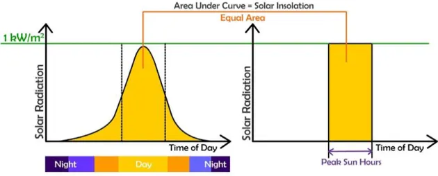
If this value is divides by 1000 𝑊/𝑚2 , which is the irradiance in Standard Test Conditions (STC), we obtain the Number of Peak Sun Hours (PSH). This is the number of hours of irradiation per day considering a constant irradiance of 1000 𝑊/𝑚2.
Figure 7. Calculation Solar Blog
Once we have the number of peak solar hours we can calculate the energy provided by the solar system:
21
CHAPTER III. Preliminary Design
This chapter sums up the development and progress of the project itself, from the beginning and the first sketches to the final result. All the steps covered are explained until the final design is found.
Since the main objective of this project consists in the construction of the project, as we progressed in it, the design of this project has been modified and constantly improved to solve the problems that were arising, following the philosophy of design and redesign.
The Moving Lab requires certain characteristics such as toughness, mobility, easy to handle for the operator and, as it is mobile, it has also to be prepared to function in any kind of path or place. The unit must be able to unfold itself when needed and fold when
it’s not necessary anymore.
Following these specifications, first ideas were thought and afterwards drawn to evaluate them. Despite being only preliminary designs, they helped a lot to understand what we were able to do and what not. They showed with real dimensions and good accuracy how could the ideas respond in real life. For example, about the height of the deployed PV array, the number of solar panels that we were able to put, where and how to put them and showed also the potential problems we could face as which system could we use to tilt it up.
1.
Design stages
It is important to note that at the beginning of this project the only known data were the challenge of the project and the dimensions of the trailer:
Length: 2570 mm
Width: 1570 mm
Height: 2100 mm
From here the beginning was to narrow the idea and the dimensions of the project and study all the possibilities of this.
First, other designs of mobile solar systems available in the market were studied to obtain ideas and serve as inspiration while designing.
22 economical design to facilitate its construction. During this stage the idea of the project is specified, and the following questions are posed:
▪ Dimensions of the trailer and roof shape.
▪ Number of panels and layout.
▪ Elevation system
▪ Material and structure of the PV array.
▪ Solar tracker or fixed.
The third stage of the design consisted in the creation of the CAD model, using the Autodesk Inventor tool. In this stage the model that will be carried out is developed.
Finally, as a final phase the design is modified while it is being built to solve the possible errors that arise.
2.
State-of-the-art
Currently, there are many kinds of Solar Trailers or Solar Powers Units that have been already built and that are available in the market. One of the goals of this project is to simplify the design as much as possible, so by taking refences and details from other similar project will help to enhance the design and to give solutions for potential problems.
To achieve these specifications, some mechanical and structural notions must be taken into consideration. Due to this fact, before creating The Moving Lab, I decided to study some bigger designs. In this way, I can compare them and draw some conclusions.
2.1. Solar Trailer
23 In addition to large fold-out solar arrays, they often include a backup generator. The generator is used to recharge the battery bank or cover large power demands. The more sun-hours available, the fewer hours the generator is required to run to recharge the batteries. For example, our MREU unit but we are just focusing in the structural solutions they have used.
Example 1
3000 Series Part SLR-7505-12AH – Patriot Solar Group
The Patriot Solar Group product is a little trailer with a low power capacity which mission is to be deployed quickly and easy.
Figure 8. Example 1. Solar Trailer Folded Figure 9. Example 1. Solar Trailer Unfolded
Mechanical / Technical Data
Body Injection Molded Polythylene
Dimensions Box 1870mmL x 1500mmH x 1200mmW
Maximum Solar Power 720W
Maximum System Voltage 12VDC
Batteries 980AH - 1200AH
Maximum Power Output 5000W
Frame Angle Iron
All Welded Construction
24 Wheels and Tires
Deploy System Gas Springs
Table 4. Patriot Solar Group Trailer Mechanical Specifications
From this design we take the idea of possible gas springs, easy to be supplied and mounted. The laterals panels idea becomes an option and since we have problems with where to fix the frames because the trailer walls are not strong enough, the option of adding extra bars in one face is showed.
In this trailer we can see for the first time the sliding guides for deploying the panels. It is an idea that gives and easy-deployed-system. It would allow us to place more solar panels in less space.
Example 2
GT916 Trailer – GreenTow
GT916 is a towable power generation unit powered and charged by solar arrays. The size is increased so the power as well.
Figure 10. Example 2. GT916 Solar Trailer – GreenTow
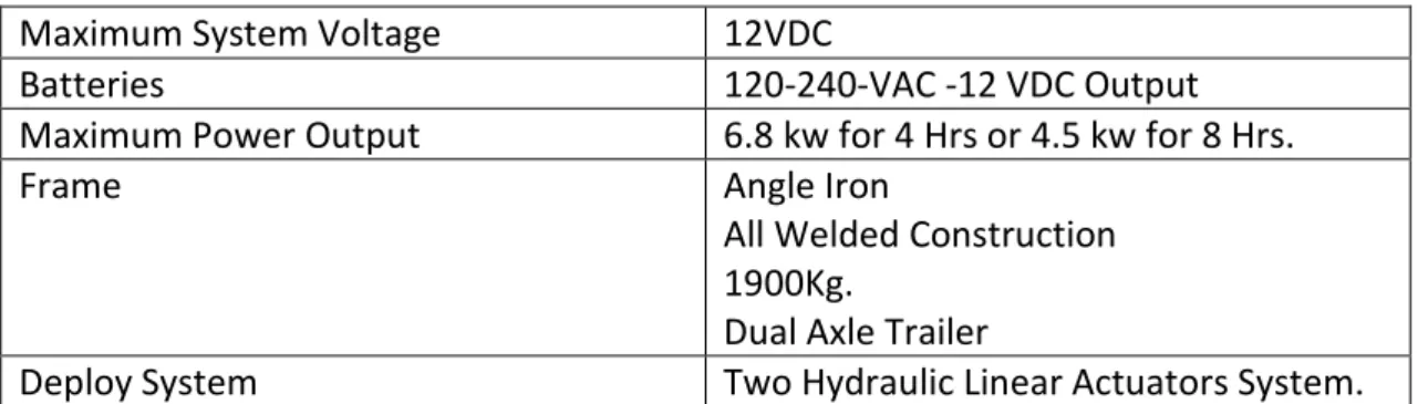
Mechanical / Technical Data
Body Aluminium, Iron Welded Structure
Dimensions Box 4400mmL x 1500mmH x 1350mmW
25
Maximum System Voltage 12VDC
Batteries 120-240-VAC -12 VDC Output
Maximum Power Output 6.8 kw for 4 Hrs or 4.5 kw for 8 Hrs.
Frame Angle Iron
All Welded Construction 1900Kg.
Dual Axle Trailer
Deploy System Two Hydraulic Linear Actuators System.
Table 5- GreenTow Trailer Mechanical Specifications.
This energy unit is the first medium-big size unit we studied. The main point is that the roof is even less wide than ours from what we can get a view of the solar panels position. In this case they solve the problem of the space by using a slide guides to move the panels what helps them to save the lack of space.
In this model we first saw the linear actuator system for deployment. It is a hydraulic system powered by a generator system. In our case it would be electric due to the fact that we don’t want our laboratory to be mix-powered.
Example 3
TMSPDC – Ok Solar
This line of portable solar units provides stand-alone photovoltaic power. These portable units supply AC power just about anywhere the sun shines. This systems is fully assembled for immediate use in the field. What is more, it has a self deployable automatic solar modules position, which can be vary and programed.
Mechanical / Technical Data
Body Iron Welded Structure
Dimensions Box 3400mmL x 2000mmH x 1530mmW
Maximum Power Input No imput
Maximum System Voltage 12VAC or DC
Batteries 24V, 800Ah
Maximum Power Output 6KW AC Power, !8 KW DC Power
Frame All Welded Construction
2300Kg.
Trial axle trailer
Deploy System Two electric linear actuators system.
26
Figure 11- Example 3. TMSPDC – Ok Solar
The idea of the slider guides is reinforced. The similarities in dimension gives us a straight road to design. After watching this example, we started with our second model which has a lot of similarities with this one.
We didn’t take the idea of the electric linear actuator until we dismissed the lead screwed one due to its price.
Example 4
MREU – UCLL
The main source of inspiration for being the previous idea of our project. From here we took the main ideas of the structure, the actuator, the dimension of the panels, the system hinges.
27
Figure 12. Example 4. MREU – UCLL
2.2. Mobile laboratories
A mobile laboratory is a laboratory that is either fully housed within or transported by a vehicle such as a converted bus, or tractor-trailer. Such vehicles can serve a variety of functions, including: science education, science research, air, water, and soil analysis and monitoring as well as biosafety. Mobile laboratories, vehicles and trailers are designed to meet all possible requirements for rugged use in cold or tropical climates and all instruments are usually securely mounted on specially designed shock absorbers to avoid damage during driving.
For these reasons they are a good example of study because, to meet these specifications, it has special designs from which we can take several ideas.
Example 5
MS-225 SOLAR GENERATOR – Mobile Solar
28
Figure 13. Example 5. MS-225 SOLAR GENERATOR – Mobile Solar
This model is a good example of what we have done at the end. Simple and easy, one of our goals. The side frame has been inspired in this model.
Example 6
The SkyFire Energy Solar Energy Station
Figure 14. Example 6. The SkyFire Energy Solar Energy Station.
29
2.3. Conclusions
The main conclusions and ideas that we draw from these examples are the following:
▪ Solar panel deployment system with sliding guides (Examples 1,2,3,6)
▪ System of deployment of the set with lead screw actuator (Example 4)
▪ Colocation of 8 solar panels in longitudinal arrangement to the trailer to maximize solar uptake (Example 3)
▪ System of metal frames as structural support instead of directly attach
everything to the trailer’s roof. (Example 5)
As we know, not all these ideas have been possible to be implemented. Thus, some different solution from these examples were taken later:
▪ Solar panels deployment by hinges with a side frame and an upper frame like in example (Example 5)
▪ Gas springs use (Example 1)
▪ Electric linear actuator (Example 3)
3.
Problems faced
During the development and construction of the project there have been many problems that had changed our designs. Some solutions were alternatives already studied while others had to be taken at the time. This has been one of the great challenges of the project and daily work. The most important ones are shown here.
3.1. Dimensions of the trailer
30 After the trailer arrived we figured out that it was higher because the trailer’s frame was not count. This supposes an increase of 115 mm more and the height of the frames to adapt the PV array to the structure of the trailer. We had to dismiss these ideas to make it simpler.
Figure 15. Trailer Frame Front view, Autodesk Inventor
The solution adopted was to design a simpler model of two different frames, a lateral one locked on one side of the trailer and an upper one, flatted and with just one level.
3.2. Trailer’s frame
The trailer came with a frame on its roof (the dimensions of the roof rack are widely explained in Chapter IV) which meant we had to figured out how to mount our PV array on it. It also meant that our structure was going to be higher than we had supposed.
Another problem added was that the faces of the trailer where we wanted to fix our structure were very weak. This would not allow us to put the weight and forces of the PV array on it.
At the end the roof rack came in handy to be used as the attachment point on the trailer and to make an empty space between the trailer and the PV array. This space is needed to give the actuators enough angle to tilt the structure up.
3.3. Number of solar panels and layout
The designs came with the idea of holding as many solar panels as possible to maximize the output power.
31 answer. The MREU panels are 1660 x 990 x 50 mm so that was the designing dimension to start with.
Due to the dimensions of the trailer’s roof, a rectangle of 1570 x 2750 mm, a total of
4,375 m2. The best option was to put the panels in their horizonal side so that the maximum distance on the width way were 990 + 990 = 1980 mm, not exceeded the towing dimensions law which is 200 mm more in each side of the trailer. On the length direction we had no problem.
The number of solar panels with the sliding guides idea were 8 solar panels. After the idea had to be dismissed we planned to place 6.
3.4. Unfold system angle
Derived from a problem related to the height of the trailer we have to design the lowest possible solar system structure. This is a problem for the actuators, regardless of the system used.
The little space available between the roof of the trailer and the solar panel´s frame makes the initial angle, with which the actuator pushes the frame, very low. This produces that the cosine of the forces is very high - or that the sine is very low - which means that our force is almost horizontal.
Figure 16. Actuator Forces Distribution with Low Angle, Autodesk Inventor
32 only appears in the first moments of the deployment of the PV array since as the angle increases, the force becomes more vertical and the effect disappears.
During the construction we realized that a space of at least 100 mm was necessary between the frame and its rest position. This left us three viable solutions:
▪ Leave the Upper Frame in a non-horizontal resting position. This would increase the initial angle. The problem is that it affects aesthetics.
▪ Reduce the position height of the actuator as much as possible. Being closer to the frame, the angle would be higher. The difficulty would be in holding it securely in such a low position, away from the support frame.
▪ Include some Gas Springs that help to give that extra impulse in the first moments of the deployment.
The solution adopted was a combination of the last two. Two Gas Springs are included in the design and it is tilted enough so that it is not perceived.
4.
CAD model
4.1. Software
One of the project’s goals is to create a 3D model of the design. To carry out this work, the software tool Autodesk Inventor Professional 2018 has been used, a powerful 3D design tool that has served as a guide for the design of our project. With its help it has been possible to model and visualize the project in each stage of its realization. The primary objective has always been the learning of the software for the modeling of the design to obtain the plans and representations of our project.
More specifically, the Frame Generator function of Autodesk Inventor has been learned, which has been used to design the frame and PV array.
4.2. First Design
33
Figure 17. Solar Panels View of the First Design, Autodesk Inventor.
The initial intention of the project was a design of 8 solar panels placed in three different blocks, one of 4 panels under two others with 2 panels each that would be deployed on a sliding rail guide. Those would place the solar panels at the ends of the trailer before being tilt. As has been shown previously - 3.1. Dimensions of the trailer – the number of solar panels and the sliding guides idea had to be dismissed.
Figure 18. Sliding guides.
34
Figure 19. First actuator design, Autodesk Inventor.
Its key features are:
First Design
Solar Panels Number
Unfold System Supporting Point Difficulties
8 solar panels in two levels (1660 x 990 x 50)
Linear axe with lead screw drive.
4 hinges for the whole PV array
Height, design and construction very complex
Table 7. First design features.
4.3. Second Design
The second CAD design is more elaborated. It has less solar power because we removed two solar panels which also means its design and construction are simpler. The main ideas that will later evolve to the final model are implanted.
It begins to design with the Frame Generator. It is designed in aluminium using two different types of profiles - A more detailed explanation of the profiles is given in the Chapter IV)
▪ L-shaped Profile: 50 x50 x3 mm.
35 The system of the structure of three different metallic frames is designed: The Bottom Frame, attached to the Trailer Frame and that serves as support of the other structures and of the actuator. The Main Frame and the Lateral Frame are designed to support the panels.
Figure 20. Previous hinge design in the second design, Autodesk Inventor.
The design of the hinges is simple and effective but requires more material and workshop work. Moreover, the systems with two different hinges implies an added difficulty for the panels to be aligned, which requires much more precision when working with the profiles and mounting them.
36 Its key features are:
Second Design
Solar Panels Number
Unfold System Supporting Point Difficulties
6 in two different frames (1660 x 990 x 50)
Linear axes with lead screw drive.
4 hinges for the main frame and 4 for the lateral frame integrated in the beams.
Complex and expensive lifting system. Two different supporting points.
Table 8. Second design features.
4.4. Final Design
The final design is the result of enhancing the second design, simplifying it and adding new components. This last model has been being redesigned during the construction stage which has allowed us to correct possible errors or problems of the second design and find alternative solutions to the most complex parts of that design.
This last model has the new dimensions of solar panels, the redesign of the hinges, much more simple and effective, a new linear actuator that modifies the unfold system, the introduction of new components such as gas springs, the design of the lock point and of the props when the PV array is folded
Its key features are:
First Design
Solar Panels Number
Unfold System Supporting Point Difficulties
6 in two different frames (1640 x 990 x 35)
2 Linear Actuators and 2 Gas Springs.
4 hinges for the main frame and 4 for the lateral frame, made by pieces.
Small probems while build.
Table 9. final design features.
37
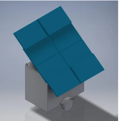
Figure 22. Right view of the final design, Autodesk Inventor.
38
CHAPTER IV. Structural description
This chapter is a description of the final structure of The Moving Lab completely finalized and operational. In it, the distinct parts that compose it will be studied with the help of images of the real model and the CAD model.
The purpose of this chapter is to show the final design in a simple, clear and detailed way.
1.
Components.
1.1. Beams
First of all, the whole project has been built in Aluminium. Physically, chemically and mechanically aluminium is a metal with valuable properties. It can be melted, cast, formed and machined easily. These features make it the suitable material to be used in this project.
One of the most important points of aluminium for use in construction is its exceptional strength / weight ratio. Aluminium is a very light metal with a specific weight of 2.7 g/cm3, about a third that of steel. By using it we make the design lighter so less force will
be needed.
In the workshop, we had access to the following types of aluminium beams:
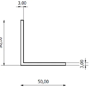
UNI EN 10056 – L 50 x 50 x 3
39
Figure 24. UNI EN 10056 – L 50 x 50 x 3
SOLAR PROFILE 45 x 45 2N180
Used to hold the PV panels in the leaning parts. Two beams of this type are necessary to
hold one single panel. It is rough and very easy to be linked, that’s why we also use it to
vertebrate the estrucuture and to link each part. This is the main beam of the strucutre.
40
1.2. Bolts and Nuts
The material used in this project is divided into two.
On the one hand the screws and nuts needed for the square profiles come from the same supplier. We have used the T-Nuts shown in the Figures and M8 x 30 screws with hexagonal head. The holes needed for this type of screws were of diameter 8.
Figure 26. T-Nuts used in the square profiles.
On the other hand, M10 and M12 screws of different lengths have been used for the other parts links. The M10 mainly for most of unions in between L profiles, and the M12 for the longitudinal holes with the square profiles. All of them are allen circular headed screws like the ones showed in the Figure:
41
2.
The trailer
This boxed trailer has been chosen due to its suitable dimensions to hold a small laboratory inside. The trailer has a solid hot dip galvanised chassis that will hold and withstand erosion for years. The trailer has been equipped with a side door and a rack roof on top. It has 342 Kg weight and its dimensions are showed in the following images:
Figure 28. Front view of the trailer.
2
1
0
0
mm
42
Figure 29. Left view of the trailer.
Figure 30. Right view of the trailer.
1
5
3
0
mm
910 mm
2
1
5
mm
2570 mm
1
7
4
5
mm
43
Figure 31. Back view of the trailer.
665 mm
665 mm
1
2
0
44
3.
Frames
All the frames have been designed with the Frame Generator tool of Autodesk Inventor as it is mention in Chapter III.
The design of the structure is made up of three different frames, each with a purpose, plus one that comes attached to the trailer. They described below:
3.1. Trailer Frame
This frame comes standard with the trailer and is attached to it by metal plates that are welded to the roof of the trailer.
It is welded made in steel beams of 30 x 30 x 3 mm. It dimension is 2505 x 1430 mm in the exterior parts. Drawing are included in the Chapter VIII - Annexes.
Figure 32. Trailer Frame detail, Autodesk Inventor.
45
Figure 33. Trailer Frame top view detail, Autodesk Inventor.
It is in this frame where the supporting frame is bolted, which makes it very important at the structural level.
3.2. Support Frame
Figure 34. Support Frame top view detail, Autodesk Inventor.
It is the main component of the structure. On this frame, through the hinges placed on it, will be supported the two frames that holds the solar panels. What is more, it is the fulcrum point of linear actuators and gas springs.
46 correct alignment of the panels since the hinges that serve as support will be placed on it.
Its design is meant to be easily placed on the Frame Trailer. Since this project has been built by students, it has always been a matter of designing easy-to-assemble components. It is composed by two longitudinal L profile 50x50x3 mm beams of length 2725 mm and other four transverse square profile 45x45 mm of 1600 mm each. It also has another set of longitudinal beams that serve as support for the actuators. For more details, drawing is included in the Chapter VIII - Annexes.
The L-shaped profiles are positioned so that they can be joined by bolts with the Trailer Frame and with the transverse beams. Its purpose is to join the structure with the trailer, the two profiles act as a "sandwich" closing on the rectangular structure. Between the L profiles and the Trailer Frame there is a 6 mm space that has been left to correct possible errors of assembly or construction. This space is filled with washers in the union bolts to facilitate correct and safe fixing.
Figure 35. Detail of the join system to the trailer, Autodesk Inventor.
The square cross sections are the supports of the entire structure. Above them the hinges are placed. The hinges join the other frames and they are the rest points on which the Top Frame rests when it is not deployed. For a correct alignment of the solar panels these are also collinear with the four transversal profiles of the other two frames. The Gas Springs are also supported on the outermost profiles.
47
3.2.1. Actuators fulcrum
Attached to the transversal profiles by 12M bolts are the points of support of the linear actuators. This is a very reinforced structure, composed of three profiles on which the loads of the actuators are supported when deploying and closing the Top Frame.
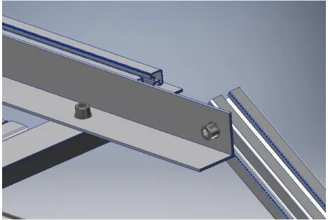
In the upper part there is an L profile that serves as an extra grip for the main beams. This is screwed to the transverse beams from above. In the middle is the square profile screwed at its ends. This is the main component and the one that receives most of the load of the actuator. In the lower part there is a square profile that crosses underneath the entire support frame linking the two actuator fulcrum beams.
Figure 36. Actuator fulcrum in The Moving Lab.
48
3.2.2. Hinges
The hinges have been made in the workshop and are made of aluminum. They are a very important component of the project because all the PV array is linked in them. In addition to allowing the rotation its function is to align the frames so that the solar panels are in the same line. It also support the weight of the structure.
There are two types of hinges, one for each frame, and each frame carries eight which make a total of 16 hinges in the trailer.
The hinges for the Top Frame are 195 x 60 x 10 mm.
The hinges of the Lateral Frame are 100 x 45 x 10 mm.
Figure 37. Hinges in The Moving Lab
Both hinges are placed at the end of the square profiles of the Support Frame and their distance and position have been calculated so that the panels rotate at the correct point. They also keep a security distance between the two frames.
49
3.2.3. Rest points
The rest points are four square profile bars 115 mm length, placed vertically on the support beams. When the Top Frame is unfolded it rests on the rest points. They are designed to fit perfectly in the spaces of the beams of the Top Frame.
Figure 38. Rest points in The Moving Lab.
Its main function is to keep the structure safe when the trailer is towed. Avoiding bumps due to bumps and vibrations.
3.3. Top Frame
This metallic structure supports four solar panels and its main feature is that it is deployed automatically. Its design is made to be as simple as possible but still strong enough to withstand the load of the actuator.
50
Figure 39. Detail of the Top Frame, Autodesk Inventor.
In addition, another beam of profile has been placed along with one of the L profile in which the actuator is subject to reinforce its hardness. The length of the L profile is 2625 mm and that of the square profiles is 1980 mm.
51 This frame is linked to the rest of the structure through the hinges and the actuators. To connect them to the hinges, the square profiles have been made a transverse hole at 255 mm. This distance has been calculated so that the panels are perfectly placed in the centre of the trailer.
3.4. Lateral frame
The Lateral Frame or Side Frame is placed on one side of the trailer. Two solar panels are fixed on it. Its structure is the smallest of all and it also follows the same design pattern.
It consists of four square profile beams on which the solar panels are fixed. To join these profiles, other square profiles are bolted through its central hole and M12 screws to them. This design allows to have a less thick frame that project less from the side of the trailer.
Figure 41. Detail of the Lateral Frame, Autodesk Inventor.
It is attached to the rest of the structure with the same system of hinges as the Top Frame. At the other end is fixed to the trailer through blocking points that allow two things.
52 connect the support beams. Due to this fact, these lock points are at the same vertical distance as the frame.
Figure 42. detail of the lock points in The Moving Lab.
53
Figure 43. Lock beams for the Lateral Frame in The Moving Lab.
3.5. Linear actuator
As a linear actuator we have used the Easyswing 200 door opener from HBopeners because the movement required by our frame is like a door. This actuator is suitable for a door of up to 2 meters and 200 KG per side providing enough power to ours which is around 100 KG and of similar dimensions.
The motors that work in 24 V are more powerful than most other gate openers that work with 12 V. It also has many adjustment options, including automatic closing after
54
Figure 44. View of the actuator placed in The Moving Lab.
Two actuators have been mounted so that they reach the necessary power to raise the frame without problems. In addition, as already mentioned in previous chapters, its placement has been carefully designed to optimize its movement to the maximum and not produce problems of high loads in the structure.
55
Specification Description
Torque 1500 Newton
Weight 3,6 KG
Dimensions of retracted motor 65 x 9.8 x 19 cm Dimensions of the extended motor 101 x 9.8 x 19 cm
Motor 24 V
Table 10. Specifications of the actuator Easy Wing 200.
It also comes with two remote controls to unfold or fold the PV array when it is required.
3.6. Gas springs
As already advanced in previous chapters, two Gas Springs has been used to help to lift the Top Frame in the initial moments.
Its size has been dimensioned through a web page that has given us the following values based on the weight, size and placement of the Top Frame:
Figure 46. Dimensions of the gas spring location.
56
CHAPTER V. Building process
In the previous chapter the dimensions and features of the trailer are explained in detail. For the final design the trailer has been painted and stickers have been placed with the logos of the UCLL Hogeschool and the project’s name. This has been done to decorate the trailer and make it more eye-catching for the public. The final trailer looks like this:
The building process has been developed mainly in the workshop. In this chapter some of the machines and tools used for the construction of this project are described, as well as some images that visually explain the construction process.
1.
Tools and materials
For the beams we have used 6 meters profiles unities. To manipulate the beams, we have used the tools shown in the following images:
57 The drills used have been of Ø12, Ø10, Ø8 and a centre drill. In this order are shown in Figure 47.
The unions between beams have been done with screws. For the square profile we have used a special type of joints, T-Nuts. In the following Figure we can appreciate how it fits in the beam.
Figure 48. Detail of the T-Nuts in the beams.
To manipulate the beams, we have used the machines used in the two following images. The saw is from VM services (Figure 49). The drill is from Malilla (Figure 50). All these materials can be found in the workshop of the UCLL.
58
Figure 50. Drilling Machine, IMA Malilla.
2.
Procedure
The procedure of building The Moving Lab was the following:
First, we sawed and drilled all the profiles with the drawings arisen in Inventor. In this stage we also cut slides from the billets (see Figure 51) for the hinges and the lock points in aluminium and plastic pieces.
59 Once we had all the beams and the drawings, we started mounting and screwing all the parts. We built each part on the floor (see Figures 52 & 53) or directly to the trailer (see Figures 54 & 55) to finally attach them all together. The best solution for couple the pieces was a single girder cranes placed in the Technology Building as shown in Figure 54.
Figure 52. Construction of the Top Frame detail.
60
Figure 54. Mounting the Top Frame to the trailer.
61
3.
Electric assembly
During the construction of this project, as part of my work, I have also helped with the installation of the electrical components as well as to build the mechanical parts on which they are assembled.
62
CHAPTER VI. The box
1.
Introduction
Along with the development of The Moving Lab this project includes the design of an air quality measurement device as an application of The Moving Lab.
The air quality device consists of a box in which different sensors and electronic devices will be introduced such as wireless connection or vacuum pumps to take measurements of the air in unusual conditions. My work on this field has consisted in the design of the lay out and de shape of this device. The modelling work has been carried out by Dennis Maes.
Due to the elements that make up the device, the requirements of the box vary. To achieve this aim, we have divided the design in two different devices, each one satisfies different purposes. The wide mobility of The Moving Lab allows to place or use any of these boxes in the places where they are required.
The work in this project has not been completed to the end because the sensors that the University wanted to use have still to be specified. What has been achieved is to design two prototypes in 3D models with the Autodesk Inventor tool and finally built with a 3D printer one of them. The sensors used are standard.
The key idea of this project was to:
▪ Keep everything compact
▪ keep the installation process faster and reproducible
2.
Description
63
Figure 56. Raspberry Pi.
This gives the device the capability of providing remote monitoring data from on-board sensors. This information is transmitted to The Moving Lab operator’s tablet for to be
viewed live and logged.
The enclosure is a weather proof electrical box. The Raspberry Pi board is easy to spot mounted to the bottom of the case. Along with it a battery is meant to be as it provides a USB port and enough current to operate the Pi and the sensors. On back is a 3G modem used to access the data remotely - although it can log to the SD card for collection later.
The sensors we have worked with are the followings:
2.1. Sensors
▪ Digital universal particle concentration sensor – PMS5003
Figure 57. Particle Monitor Sensor, PMS 5003
64 suspended particles in the air or other environmental improvement equipment’s to provide correct concentration data in time.
▪ SO2-B4 Sulfur Dioxide Sensor
▪ NO2-B43F Nitrogen Dioxide Sensor
▪ OX-B431 Oxidising Gas Sensor
Figure 58. Alphasense B4 serial sensors example.
3.
Drone model
–
Flying Laboratory
Refineries, petrochemical plants, and many other processes have emissions that are difficult to sample using traditional methods. The use of drones opens a whole new dimension in air sampling by allowing the operator to take direct samples from odour plumes and other sources that are difficult and /or dangerous without exposure to physical or chemical hazards. Taking samples at various heights upwind and downwind of the plant allows for accurate measurement of all emissions generated by the plant without the need for source sampling.
65
Figure 59. Drone M600, Djicdn.
66
Figure 60. Inside details of the Flying Laboratory, Autodesk Inventor.
The Flying Laboratory has essentially three main parts:
▪ The B4 sensor (any analog or digital sensor can work). Left in the main box.
▪ Sample taking tube (entrance for the sensors). Front in the main box.
▪ Pump and tubes (for the B4 sensors). Middle in the main box.
▪ The PM sensor (particle concentration sensor). Right in the main box.
▪ Power and electronics (any electronic component required). Back in the main box.
Electronics
PM Sensor
B4 Serie Sensors
Sample Taking Tube
67
Figure 61. Detail of the box placed in the drone, Autodesk Inventor.
68
4.
Pole model
–
Air Quality Monitor
Since monitoring equipment is expensive, measurements of air pollutants are taken at relatively few locations, and while this is important, more individualized information is also necessary. The standalone package can be taped, screwed, bolted, or bungeed at the target location with a minimum of effort and will immediately start generating sample data.
The layout and sensors vary. This device is designed to be installed on a pole and as it is powered by solar energy, it requires a minimum of maintenance. Its design is waterproof: the cover is sealed with a rubber ring and the air inlets and outlets are protected with a plastic tube.
This box has been printed with a 3D printer to be used as a prototype.
B4 Serie Sensors
Rubber Ring
Solar Panel
69
CHAPTER VII. Conclusions and References
1.
Conclusions
This Thesis sums up five months of working in The Moving Lab. In it I have tried to detail the work to the most so that other people can be able to learn, work and enhance my project. At the beginning of this Thesis, several goals were defined. To achieve them, I have been helped by fellows and professors till the last day.
During the development of this project I have learnt about solar energy, both the electrical part and the mechanical part. Now I understand better the operation of renewable energy systems. I have learned how to use the software tool Autodesk Inventor Professional 2018, a knowledge that will help me in my future career. With it I have been able to realize an effective, simple and real design of The Moving Lab, fulfilling the requirements and the demands of the project as well as the university’s and my professor’s.
As a priority I have been able to build the project myself. After arduous work we managed to meet the deadline, The Moving Lab has been completely built and is fully operational. On the days that this project ends, it is being exposed on other campuses.
Lastly, although we did not go beyond the prototype phase, we set the basis for future work on air quality measurement devices. Project that the university will take again next semester.
During my stay at the UCLL I have been able to develop my personal and professional skills. I have grown as a person and as an engineer. The opportunity they have given me, to make such a fascinating and beautiful project, to be able to build it with my hands, has been a wonderful experience. I have learned a lot and I am taking a new and different concept of engineering and its possibilities.