Preprint of the paper
"A Boundary Element Formulation for the Substation Grounding Design"
I. Colominas, F. Navarrina, M. Casteleiro (1999)
Advances in Engineering Software Journal, 30 , 603--700.
DESIGN
I. Colominas, F. Navarrina, and M. Casteleiro
E.T.S.de Ingenierosde Caminos,Canalesy Puertos. Dpto. deMetodos Matematicos y Representacion
Universidad de LaCoru ~na
Campus de Elvi ~na. 15192|La Coru ~na,SPAIN
Tel:(+34).981.16.70.00; Fax:(+34).981.16.71.70
E-mail: [email protected], [email protected] , [email protected]
Abstract
A Boundary Element approach for the numerical computation of substation grounding systems is
pre-sented. In this general formulation, several widespread intuitive metho ds (such as Average Potential
Metho d)can b eidentied as theresultof sp ecic choices forthe testand trial functions and suitable
as-sumptions intro duced in theBEM formulationtoreduce computational cost. While linear and parab olic
leakage current elements allow to increase accuracy, computing time is drastically reduced by means of
new completely analytical integrationtechniques and semi-iterative metho ds for solving linear equations
systems. This BEM formulation has b een implemented in a sp ecic Computer Aided Design system for
groundinganalysis develop ed inthelastyears. Thefeasibility of thisnew approachisdemonstratedwith
its application toa real problem.
KEY WORDS :EarthingComputation, Boundary Element Metho ds,Grounding GridDesign
1 Intro duction
In general, a safe earthing system has the objectives of granting the integrity of equipments and the
continuityof theservice underfaultconditions |providingmeanstocarryanddissipate electric currents
into the ground| and safeguarding that a p erson working or walking in the surroundings of grounded
installations is not exp osed to the danger of suering an electrical sho ck. To achieve these goals, the
equivale nt electrical resistance of the system must b e low enough to assure that fault currents dissipate
mainlythroughthegroundinggridintotheearth,whilemaximump otentialgradientsb etweenclosep oints
on theearth surfacemustb e keptundercertain tolerances(step, touchand mesh voltages)[1,2].
Physical phenomena underlying fault currents dissipation into the earth can b e mo delled by means of
Maxwell'sElectromagneticTheory[3]. Constrainingtheanalysistoobtain theelectrokinetic steady-state
resp onse and neglecting the inner resistivity of the earthing conductors |therefore, p otential can b e
assumedconstantin everyp oint ofthe electro dessurface|,the3Dproblemasso ciated withan electrical
current derivation toearth can b ewrittenas
=0grad(V); div () =0 in E;
t
n n n n n nn n n n n n n n E
=0 in 0 E
; V =V 0
in 0; V 0!0 if jxxxxxjxxxxxxxxx !1;
(1)
whereE istheearth,
its conductivity tensor,0 E
theearthsurface,nnnnnnn n n n n n n n E
its normalexterioruniteldand
atanarbitraryp ointxxxxxxxxxxxwhentheelectro deattainsavoltageV 0
(GroundPotentialRiseorGPR)relativeto
adistant groundingp oint assumedtob eatthep otential ofremote earth. SinceV and
areprop ortional
totheGPR value, thenormalizedb oundary condition V 0
=1 isnotrestrictive atall.
On theother hand, theleakagecurrent density atan arbitraryp oint of the earthing electro desurface,
thetotalsurgecurrentI 0
leakedintothegroundwhenfaultconditionso ccur,andtheequivalentresistance
of theearthing systemR eq
(apparentresistance of theearth-electro decircuit) can b ewrittenas:
= t
n n nnnnn n nn n n n
n; I
0 =
Z Z
0
d0; R
eq =
V 0 I
0
: (2)
b eing nnnnnnn n n n nn n
nthe normalexterior uniteld to0.
Forpracticalpurp oses,thehyp othesis ofhomogeneousandisotropicsoil can b econsideredacceptable [2],
anditsconductivitytensor
canb esubstitutedbyameassuredapparentscalarconductivity. Otherwise,
sincethekindoftechniquespresentedinthispap ercanb eextendedtomulti-layersoilmo dels(thesemo dels
represent theground stratied intotwoor morelayers of appropriatethickness each one with a dierent
valueof[6]),furtherdiscussionandexamplesarerestrictedtouniformsoils. Ifone furtherassumesthat
theearthsurfaceishorizontal,symmetryallowstorewrite(1)in termsofaDirichletExteriorProblem[5].
In practice, the particular geometry of the earthing electro de in most electrical installations |a grid of
interconnectedbarecylindri cal conductors,horizontally buriedand supplemented byanumb er ofvertical
ro ds,whichratiodiameter/lenghtusestob erelativelysmall(oftheorderof10 03
)|makesverydicultto
obtain analytical solutions tothis kind of problems. Therefore, theuseof standardnumerical techniques
(such as Finite Dierences or Finite Elements) requires the discretization of domain E, and to obtain
suciently accurate results should imply unacceptable computing eorts in memory storage and CPU
time.
On the other hand, since computation of p otential is only required on the earth surface 0 E
, and the
equivale nt resistance can b e easily obtained in terms of the leakage current density at p oints of the
earthingelectro desurface(2),aBoundaryElementapproach(whichwouldonlyrequire thediscretization
of thegroundingsurface0) seemstob ethe right choice [7,8,9].
2 General Boundary Element Formulation
The application of results of thePotentialTheory toproblem (1)allows toexpress thep otential V atan
arbitrary p oint xxxxxxxxxx x x x x
on the earthE in terms ofthe unknown leakage current density in 0, in the integral
form:
V(xxxxxxxxxxxxxx)= 1
4 Z Z
20
k (xxx;xxxxxxxxxxx ) () d0 (3)
withtheweaklysingular kernel k (xxxxxx;xxxxxxxx )
k (xxxx;xxxxxxxxxx ) =
1
r (xxxxxxxxxxxxxx;) +
1
r (xxxx;xxxxxxxxxx 0
)
; r (xxxx;xxxxxxxxxx ) = x xxxxxx xxxxxxx0
; (4)
where 0
0
integral equation of the rst kind on 0 with quasi-singular kernel (4), which solution is the unknown
leakage current density [5]. Moreover,thevariational form
Z Z
20
w ( ) (V(
)01)d0 = 0: (5)
must b esatised forallmemb ersw (
)of a suitable classof testfunctions dened on0.
Now,fora given setofN trialfunctionsfN i
(
)gdened on 0,andforagivensetofM2Db oundary
ele-mentsf0
g,theunknownleakagecurrentdensity andtheearthingelectro desurface0canb ediscretized
in theform
( )=
N X
i=1
i N
i (
); 0=
M [
=1 0
; (6)
and a discretized formof p otential (3)can b ewrittenas
V(xxxxxxxxxx x x x x)=
N X
i=1
i V
i (xxxxxxxxxx
xx x
x); V
i (xxxxxxxxxx
x x x x)=
M X
=1 V
i
(xxxxxxxxxx xx x
x); (7)
b eing V i
(xxxxxxx xxx x x x
x) p otential co ecients
V i
(xxxxxxx x x x xx x x)=
1
4 Z Z
20
k (xxxxxxx
x x x x x x x;
)N
i (
) d0
: (8)
Then, for a given set of N testfunctions fw j
(
)g dened on 0, the variational statement (5) is reduced
tothesystem oflinear equations
N X
i=1 R
ji
i =
j
; j=1;:::;N; (9)
R ji
= M X
=1 M X
=1 R
ji
;
j =
M X
=1
j
; (10)
R ji
= 1
4 ZZ
20
w
j (
)
ZZ
20
k (
;
)N
i (
)d0
d0
(11)
j
= ZZ
20
w
j () d0
: (12)
Inpractice,thenumb erof2Ddiscretizationsrequired tosolvetheab ovestatedequationsinrealproblems
implie s an extremely largenumb er of degrees of freedom. Moreover,co ecients matrixin (9) isfull and
With this scop e, it is p ossible to intro duce in our statement one of the hyp otheses widely used in most
of thepracticalmetho ds relatedin the literature [1,2,11]. Thus, takinginto account thereal geometryof
grounding grids in practice, it seems reasonable to consider that the leakage current density is constant
around thecrosssection ofthecylindri cal electro de [4,5].
Hence,ifwedenoteLthewholesetofaxiallines oftheburiedconductors, b
theorthogonalprojectionover
thebaraxisofagivengenericp oint
20,( b
)theelectro dediameter,C( b
)thecircumferentialp erimeter
ofthecrosssectionat b
,andb ( b
)theapproximatedleakagecurrentdensityatthisp oint(assumeduniform
around thecrosssection), equation(3) can b ewrittenin the form
b V(xxxxxxxxxxxxxx)=
1 4 Z b 2L " Z 2C( b )
k (xxxxxxxxxxxxxx;)dC # b ( b
)dL: (13)
Thisassumption of circumferential uniformityseemstob equite adecquateand notto o restrictive due to
thesp ecic geometry ofthese earthing electro des in real cases. Nevertheless,b ecause theleakagecurrent
isnotreally uniformaroundthecrosssection,b oundaryconditionV 0
=1cannotb eexactlysatisednow
ateveryp ointontheelectro desurfaceandvariationalequality(5)do esnotholdanymore. Therefore,ifwe
restricttheclassoftrialfunctionstothosewithcircumferentialuniformity,thatisw (
)=w (bb ) 8
2C(b ), (5) results: Z b 2L b w (b)
"
(b)0 1 4 Z b 2L
K(b; b )b (
b )dL #
dL=0 (14)
forall memb ersw (bb ) ofa suitable classof testfunctionsdened on L,b eing K(b; b
) theintegral kernel
K(b ; b )= Z 2C(b ) " Z 2C( b ) k ( ; )dC #
dC : (15)
Resolution ofintegral equation(14)involvesdiscretization of the domain|in this case, thewhole setof
axial lines of the buried conductors L|. Thus, for given sets of n trial functions f b N i ( b
)g dened on L
and m 1Db oundary elementsfL
g,theunknownapproximatedleakagecurrent densityb and thewhole
set ofaxial lines of theburied conductors L canb e discretized in theform
b ( b )= n X i=1 b i b N i ( b
); L=
m [ =1 L ; (16)
Inthese terms,adiscretized versionofthe aproximatedp otential (13)can b eobtainedas
b V(xxxxxxxxxx
x x x x)= n X b i b V i
(xxxxxxxxxx xx x x); b V i
(xxxxxxxxxx x x x x)= m X b V i
(xxxxxxxxxx xx x
b V i
(xxxxxxx xxx x x x x)= 1 4 Z b 2L Z 2C( b )
k (xxxxxxx x x x x x x x; )dC b N i ( b
)dL: (18)
Ontheother hand,forasuitable selection ofntestfunctionsfwb j
(b)g denedon L,variationalstatement
(14)isreduced tothesystem oflinear equations
n X i=1 b R ji b i =b j
; j =1;:::;n; (19)
b R ji = m X =1 m X =1 b R ji ; b j = m X =1 b j ; (20) where b R ji
and b j
co ecientscan b e obtainedas
b R ji = 1 4 Z b 2L b w j (b ) " Z b 2L K(b ; b ) b N i ( b )dL # dL; (21) b j = Z b 2L (b )wb
j (b
) dL: (22)
On a regular basis, the computational work required to solve a real problem is drastically reduced by
meansofthis1Dformulationwithresp ecttotheonegivenbyexpressions(9),(10),(11)and(12),b ecause
integrals on the circumferential p erimeter of electro des are taken apartof integrals on their axial lines.
However,extensive computingisstillrequired,mainly forcircumferential integrationin(18)and(21),and
furthersimpli cations arenecessaryto reducecomputing timeunder acceptable levels [5].
3.1 Simplied 1D Boundary Element Formulation
The inner integralof kernel k (xxxxxxxxxx xx x x;
) in (18)can b e writtenassum oftwoterms:
Z 2C( b )
k (xxxx;xxxxxxxxxx ) dC= Z 2C( b ) dC
r (xxxx;xxxxxxxxxx ) + Z 2C( b ) dC
r (xxxxxxx;xxxxxxx 0
)
: (23)
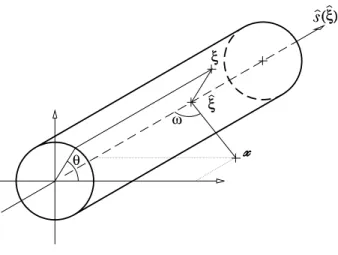
Analyzing the rst of them, distance r (xxxx;xxxxxxxxxx ) b etween anyp oint xxxxxxxxxxxxxx of the domain and any p oint at the
earthing electro desurfacecan b eexpressedas:
r (xxxx;xxxxxxxxxx ) = s x x x x x x x x x x x x x x0 b 2 + 2 ( b ) 4 0 x x xxxxx x xxxxxx0
b ( b
) sin! cos (24)
whereis theangularp ositionin thep erimeter ofcrosssection ofthecylindrical conductor,and ! isthe
angle formedbythevectorthat linksxxxxxxx x x x x x x
x withits projection b ( b 0xxxxxxx
x x x xx x
x) and theunitvectorofbaraxis b sssssss s s s s s s s( b ), that is
sin! = ( b
0xxxxxxxxxxxxx)x 2 bssssssssssssss( b ) b xxx
(ξ)
ξ
ξ
θ
ω
Figure1.{ Analysisofdistanceb etween anarbitraryp ointxxxxxxxxxxxxxxandanyp ointattheelectro de surface.
asit isshown in gure1.
The ellipti c integral obtained when r (xxxxxxxxxx x x x x;
) in (24)is substituted into(23) can b e aproximated bymeans
of numerical integration. In practice, this simpli cation is quite accurate b ecause we are interested in
computing p otential at p oints on the earth surface, which are very far from the earthing electro de in
comparisonwiththesize ofitsdiameter. Accordingly,distanceb etween p ointsxxxxxxx x x x x x x x and
b
isseveral ordersof
magnitude biggerthan thebardiameter( b
) [5]. Atthe sametime, this resultcan b e interpretedasan
approximationofdistancer (xxxxxxxxxx x x x x;
)in(24),intermsofthedistanceb etweenxxxxxxxxxx x x x x
anditsorthogonalprojection
b
andthecylindri cal diameteratthis p oint:
r (xxxxxx;xxxxxxxx ) br (xxxxxxxxxxx;xxx b ) =
s
xxxxxxxxxxxxxx0 b 2
+
2 (
b )
4
: (26)
Finally,analyzingthesecondtermin(23)inthesamewayas(24),anapproximationtothecircumferential
integral ofinner kernel in (18)can b eobtained:
Z
2C(
b )
k (xxxx;xxxxxxxxxx ) dC( b )
b k(xxxxxxxxxxxxxx;
b
); (27)
b k (xxxxxxxxxxx;xxx
b )=
1
b r (xxxxxxx
x x x x x x x;
b )
+ 1
b r (xxxxxxxxxx
x x x x;
b 0
) !
: (28)
b k(xxxxxxx
xxx x x x x;
b
) is a mo died kernel of the original one (4). In this new expression, the orthogonal projectionof
over the bar axis and the diameter of electro de are used, and distance r (xxxxxxx x x x x x x x;
Ontheotherhand,takingintoaccounttheab ove analysisofk (xxxxxx;xxxxx ), arstapproximationtoinner kernel
in (15)can nowb ederived
K(b ; b ) Z 2C(b ) ( b ) b k( ; b
)dC : (29)
Next, b earing in mind the hyp othesis used in (26), distance b etween p oints and b
can b eexpressed in
termsof thedistanceb etween p ointsovertheaxesofelectro des (band b
) andthediameter(b), sothat
kernel (15)can nowb esimplie d in thesamemanner as(27):
K(b ; b ) ( b )(b
) b b k (b ; b ); (30) b eing b b k (b ; b
) theapproximatedkernel
b b k (b;
b ) = 1 b b r(b ; b ) + 1 b b r (b ; b 0 ) ! ; (31) b b r (b ; b ) = s b 0 b 2 + 2 ( b )+ 2 (b ) 4 : (32)
The use of the unexp ensive approximations (27) and (30) to evaluate the circumferential integrals of
kernels, takesadvantage ofthe fact thatdouble integration in thegeneral b oundary element approach is
p erformedon a 1Ddomain|expressions (18)and (21)|.
Fordierent selectionsof thesetsoftrial andtestfunctions, sp ecicformulationscan b eobtained. Thus,
forconstantleakage current elements,Point Colo cation(Dirac deltas astrialfunctions) leads tothevery
early intuitive metho ds, such asthesup erp osition ofcurrent p oint sources,whereasGalerkin formulation
(test functions identical to trial functions) leads to a kind of more recent metho ds, such as \Average
Potential Method, APM"),based on theideathat each segment ofconductor issubstituted fora \lineof
p oint sources overthe length of the conductor" [13]. In these metho ds, co ecients (21) corresp ond to
\mutualandselfresistances"b etween \segmentsofconductor"[11]. Naturally,forhigherorderelementsit
is nowp ossible toderive moreadvanced formulations [5]. Furtherdiscussion and examples arerestricted
to Galerkin typ e formulations, where the matrix of co ecients of linear system (19) is symmetric and
p ositive denite [12].
Now, if we take into account simpli cations achieved in the circumferential integration and diameter of
conductorsis assumedconstantwithin eachelement, nalexpressionsforcomputing p otentialco ecients
(18)and linearsystemco ecients (21)can b ewrittenas
b V i
(xxxxxxxxxx xx x x) 4 Z b 2L b k (xxxxxxxxxx
x x x x; b ) b N i ( b
) dL: (33)
b R ji 4 Z b b N j
(b) " Z b b b k (;b
where and represent theconstant diameterwithin elements L and L . Obviously, (34)leads toa
symmetric matrix.
Nevertheless, computation of the remaining integrals in (33) and (34) is not obvious, and the cost of
numerical integration is still out of range due to the undesirable b ehaviour of the integrands. For this
reason, itis essential toderive explicit formulaein order tocomputeanalytically theseco ecients.
4 Analytical Integration of Co ecients
Successive hyp otheses intro duced in thegeneralb oundaryelement formulationhaveallowedtoreducethe
complexity of the grounding grid analysis. Thus, each cylindric al conductor can b e mo delled by means
of a segment of straight line |the electro de axis| dened byits ends, and provided with an additional
geometricalprop erty|the electro de diameter|which istakenintoaccountin the calculations.
Now,p otential createdbyan electro de at anyp oint xxxxxxxxxxxxxx of thedomain (17)can b eobtained assum of the
contributions(33)ofeachconductorofthegroundinggrid. Thesetermscorresp ondtotheitrialfunction
contribution top otential generated by theelement L
b elonging to electro de L at an arbitrary p oint xxxxxxxxxx x x x x.
Ontheotherhand,thesimplie d1Db oundaryelementdiscretization oftheproblemleadstosystem(19),
whichco ecients b R
ji
in(34)corresp ondtotheitrialfunction contributiontop otential generatedbythe
element L
overother element L
,weightedbythej testfunction.
4.1 Computation of Potential Co ecients b V i
(xxxxxxx x x x x x x x)
Anyp oint b 2L
canb eexpressedintermsofthemid-p oint b 0
oftheelementL
,itslengthL
anditsunit
vectorbssssssssss s s s s
, fora value of scalar parameter varying within the range 01and 1 (domain of isoparametric
trial functions) [14]. Thus,(33)can b erewrittenastheline integral in a singlevariable :
b V i
(xxxxxxxxxxxxxx)=
L
8 Z
=1
=01 b k(xxxxxxxxxxx;xxx
b ())
b N i
( b
())d: (35)
In the same way, it is p ossible to express the integral kernel b k (xxxxxxx
x x x x x x x;
b
()) as a function of , given that it
dep ends on terms(28)in theformbr(xxxxxxxxxx xx x x;
b
()). Thus,if wedenote p 0
thedistance b etween thep ointxxxxxxxxxx x x x x
and
its orthogonalprojectionovertheelectro de axialline,and q thedistance b etween this projectionand the
mid-p oint b 0
,distance br(xxxxxxxxxxxxxx; b
())results in
b r(xxxxxxxxxx
x x x x;
b ())=
L
2 p
(bp(xxxxxxxxxx xx x x))
2
+(bq(xxxxxxxxxx x x x x)0)
2
; (36)
(bp(xxxxxxxxxxxxxx)) 2
=
p 0
(xxxxxxx xxx x x x x)
L
=2
2 +
L
2
; q(xbxxxx)xxxxxxxxx = q(xxxxxxx
x x x xx x x)
L
=2
(37)
Obviously this analysis can also b e p erformed with the term r (xbxxxxxx xxx x x x x;
b 0
()) in (28), and we should obtain
analogous expressions in terms of new geometrical parameters pb 0
(xxxxxxx xxx x x x
x) and qb 0
(xxxxxxx xxx x x x
x), corresp onding to p oints
(xxxxxxxxxx;xx b 0
Ontheother hand,trial functionsN i (
())in (35)can b eexpressed|bymeansoftheir seriesexpansion
untilthesecondorderterm|asparab olicfunctionsin thevariable,whichco ecientsdep endonknown
values of thefunctionsand their rst and second derivatives[5].
Finally,ifwesubstitutein(35)expressionsobtainedin(36)fortheintegralkernel(28)andthosedevelop ed
for the trial functions b N i ( b
()), taking into account that b oth dep end on , it is p ossible to integrate
explici tly thep otential co ecient b V i
(xxxxxx).xxxxxxxx Aftera relatively long analytical development, (35)results in
b V i
(xxxxxxx xxx x x x x) = 4 2
8(p(xbxxxxxx x x x x x x x);q(xbxxxxxx
x x x x x x
x)) + 8(pb 0
(xxxxxxx xxx x x x x);bq
0 (xxxxxxx
x x x x x x x)) 3 (38)
wherefunction 8(1;1)dep ends onlyongeometricalparametersandknownco ecientsoftrialfunctions[5].
4.2 Computation of SystemCo ecients b R
ji
Inanalogouswaytopreviousdevelopment,anyp ointb
2L
canb eexpressedintermsofthemid-p ointb 0
oftheelement L
,itslengthL
anditsunitvectorsbsssssssssssss
,foravalueofscalarparametervaryingwithinthe
range01and1(domainofisoparametrictrialfunctions) [14]. Thus,takingintoaccountthedevelopment
achieved in (35), expression (34)can b e rewritten as two line integrals, one in the single variable and
other in ,
b R ji = L L 16 ( Z =1 =01 b N j
(b()) Z
=1
=01 b b k (b();
b ()) b N i ( b ())d d ) (39)
It may b e seen that the line integral in is similar to (35), although in this case, the integral kernel is
given by(31). If geometricalparametersp(bb
())and q (bb
())are suitablyredened, expression (35)can
b ewritten [5]|bymeansof (38)|in theform
b R ji = L 8 ( b R ji ( b 1 ; b 2
;b 1
;b 2 )+ b R ji ( b 0 1 ; b 0 2
;b 1
;b 2 ) ) (40)
whereco ecients b R ji ( b 1 ; b 2 ; b 1 ; b 2
)can b eobtainedas
b R ji ( b 1 ; b 2
;b 1
;b 2 )= =1 Z =01 b N j (b
())[8(p(bb
());bq(b ()))]d (41) b p 2 (b ())= p 0 (b
()) L =2 2 + L 2 + L 2 ; (42) b
q(b()) =
q(b())
L
=2
: (43)
On theother hand, trial functions b N j
(b()) can b e expressed|by meansof their series expansion until
thesecond order term|as parab olicfunctions in the variable ,which co ecients are known[5], in the
samewayasit hasb een previously made with b N i ( b
4.2.1 Integration of Co ecients b R
ji (
b 1
; b 2
; b 1
; b 2
)
Each co ecient b R
ji
( b 1
; b 2
; b 1
; b 2
) in (40)can b eundersto o d asthe p otential inuence generated byan
electro deonanother. Sinceelectro des arep erfectlydenedbycartesianco ordinatesoftheiraxialends,we
can analyse the rstof twoterms and apply results and formulaeobtained tothesecond one, considered
asthe integrationb etween two dierent bars (with thesymmetricp oints to b 1
and b 2
).
Therefore,integrationofco ecients(41)requiresintherstplaceageometricalanalysisoftwocylindric al
barsinthespace. Thisstudyallowstoexpressadimensionaldistancesb p(b
())andb q(b
())in(42)and(43)
asafunction of,and asetof knowngeometricalparametersdep endi ng ontherelative p ositionb etween
electro des [5]. Now, if nal expressions for bp(b()) and bq(())b derived withthe previous analysis, and
those obtained fortrial functions b N j
(b()) are substituted in (41), and we make suitable arrangements,
results in
b R
ji
( b 1
; b 2
;b 1
;b 2
) = u=2 X
u=0 w =4
X
w =0 K
(u) w
' (u) w
; (44)
where co ecients K (u) w
can directly b ecomputed from the jthtrial function, the geometrical parameters
of electro des and theithtrial function [5].
On the other hand, remaining line integrals in the variable are incorp orated in co ecients ' (u) w
(44).
Development of explicit formulae to evaluate these expressions is not obvious, and requires quite a lot
of analytical work. Moreover, this circumstance gets worse b ecause co ecients ' (u) w
dep ends also on the
geometricalparametersofelectro des, whichp ossible valuesincrease thenumb erofcasesof dierent typ es
of integralswe mustanalyse, due tosingularities thatcan b e pro duced[5].
For this reason, in the b eginnin g of this project [15]analytical expressions forthe morecommon spatial
arrangements of electro des |p erp endi cul ar and parallel bars| were derived. Although these techniques
represented a signicant improvement in the area of earthing analysis, it was necessary to complete the
analysisofintegralsindep ende ntlyofgeometricalparameters,inordertocomputethemanalyticallyinall
cases.
At present, this development has b een completely nished, and now we get ready explicit expressions
to compute all co ecients ' (u) w
, although its derivation is to o cumb ersome to b e made explici t in this
pap er [5]. These formulae have b een develop ed in order to make easy the later implementation in a
computerco de,insuchawayasitsevaluationismadeinrecurrentform,usingasfewasp ossible op erations
with transcendental functions. Nevertheless, its programming must b e done carefully, due to the huge
complexityof thenal formulaeofco ecients in (44),and its ill-condi tioni ng.
5 Application to a Real Case
This simplie d 1D numerical approach based on the Boundary Element Metho d withanalytical
E. R. BARBERA GROUNDING SYSTEM
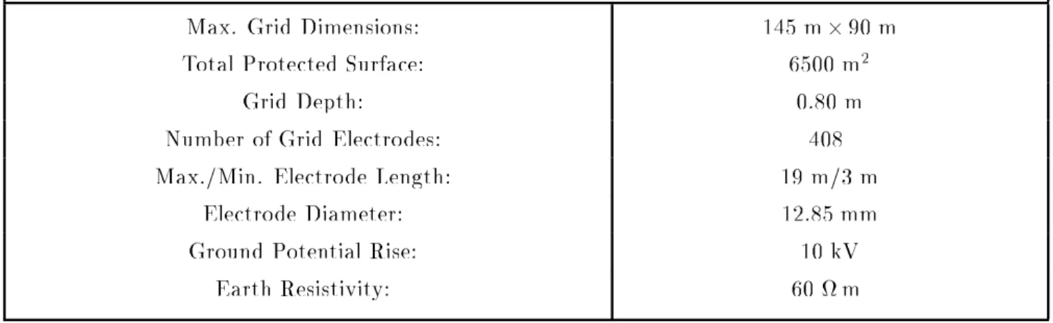
Max. Grid Dimensions: 145m290m
Total ProtectedSurface: 6500m
2
Grid Depth: 0.80m
Numb er ofGridElectro des: 408
Max./Min. Electro de Length: 19m/3 m
Electro deDiameter: 12.85mm
GroundPotentialRise: 10kV
EarthResistivity: 60m
Table1.|E. R.Barb eraSubstation: Characteristics.
Nowadays,all these techniques derived bytheauthors have allowed to develop thesystemTOTBEM for
the computer design of earthing gridsof electrical substations [16]. Withthis system, nowit is p ossible
to analyse accurately grounding grids of huge installations, with acceptable computing requirements in
memorystorage and CPUtime.
The example thatwe present is theE. R.Barb era substationgrounding, close toBarcelona, Spain. The
earthingsystemofthissubstationisagridof408cylindricalconductorswithconstantdiameter(12.85mm)
buried to a depthof 80cm,b eing thetotal surfaceprotected up to6500 m 2
. The totalarea studied isa
rectangle of135mby210m,whichimplies a surfaceup to28000m 2
. The planofthegroundinggridand
its characteristicsarepresented in gure2. a)and table 1.
Thenumerical mo del usedin theresolutionof thisproblem hasb eena Galerkin formulation. Each baris
discretized in one single constant leakage current densityelement, which implies 408degrees of freedom.
On theother hand, theground p otential rise considered in this studyhas b een 10kV (due tothe linear
relation b etween p otential and intensity, we can indistinctly consider the Ground Potential Rise or the
Total Surge Current).
Numerical results, such asthe total fault current and theequivale nt resistance of the groundingsystem,
aregiven in table 2. Moreover,gure 2.b) showsthe p otential distribution onground surfacewhen fault
condition o currs, gure2.c) representsthep otential prole alonga line, and gure2. d) is a3D viewof
p otential levelon surface. Thisnumerical mo del ofthegrounding gridhasonly required seven anda half
minutes of CPU time in a conventional p ersonal computer (i.e. PC486/16Mb to66MHz). It is obviuos
that this prop osed approach allows the complete characterization of a grounding grid in a riguorousand
reliable way,withvery acceptable computing requirements.
This example has also b een solved increasing the numb er of b oundary elements used in the numerical
mo del,bymeansofthesub divisionofeachoneoftheelectro desofthegrid. Atthescale ofthewholegrid,
elements (linear orparab olic) aremoreadvantageousin comparison withconstant elements [5].
E. R. BARBER
A GROUNDING SYSTEM:
1D BEM MODEL & RESULTS
Typ e ofElement: Constant
Numb er ofNo des: 238
Numb er of Elements: 408
FaultCurrent: 31.75kA
Equivalent Resistance: 0.315
CPU Time: 450s
Computer: PC486/66MHz
Table2.|E.R. Barb eraSubstation: NumericalMo delandBEM Results.
6 Conclusions
ABoundaryElement approachforthenumerical computationof substationgroundingsystemsdevelop ed
bytheauthorsin thelastyearshasb eenpresented. For3Dproblems,somereasonableassumptions allow
to reduce the general 2D BEM formulation to an approximated less exp ensive 1D version. Eortshave
b een particularly made in getting a drastical reduction in computing time by means of new completely
analytical integration techniques, while semi-iterative metho ds have proved to b e sp eciall y ecient for
solving theinvolved systemoflinear equations.
On the other hand, several widespread intuitive metho ds (such as the Average Potential Metho d) can
b e identied in this general formulation as the result of suitable assumptions intro duced in the BEM
formulation to reduce computational cost for sp ecic choices of the test and trial functions. Problems
encountered byotherauthorswiththeapplicationofthesemetho ds cannowb emathematicallyexplained
and sources oferrorp ointedout, while moreecient and accurate formulationscan nowb ederived.
The numerical approach prop osed is a general metho dology that |for the rst time| allows to obtain
highaccuracy results in thegroundinggrid analysisof electrical substations ofmedium/big sizes, usinga
low costand widely available conventionalcomputer. Obviously, studyof biginstallations should require
higher computing eortswithmorep owerfulcomputers, althoughalways witha very reasonablecost.
Acknowledgments
This work has b een partially supp orted by the p owercompany\Union Fenosa", by research fellowships
[1] SverakJ.G.,DickW.K.,Do ddsT.H.,Hepp eR.H.,1981,\Safesubstationgrounding.(PartI)",IEEE
Trans.on PowerApp.and Sys., 100,4281-90.
[2] Sverak J.G. et al., 1982, \Safe substation grounding. (Part I I)", IEEE Trans. on Power App. and
Sys., 101,4006-23.
[3] Durand,1966,\
Electrostatique",Masson,Paris.
[4] Navarrina F.,ColominasI.,Casteleiro M.,1992,\Analytical integrationtechniquesforthe earthing
grid computation byb oundary element metho ds", International Congresson Numerical Metho ds in
Engineering andApplied Sciences, I I,1197-1206.Concepcion, (Chile).
[5] ColominasI.,1995,\CalculoyDise ~nop orOrdenadordeTomasdeTierraenInstalacionesElectricas:
UnaFormulacionNumericabasadaenelMeto doIntegraldeElementosdeContorno",Ph.D.Thesis,
E.T.S.de Ingenieros de Caminos,Canales yPuertos.Universidad de La Coru ~na(Spain).
[6] Hepp e R.J., 1979,\Computation of p otential atsurface ab ove an energized grid orother electro de,
allowing fornon-uniform current distribution",IEEE Trans.on PowerApp.and Sys., 98, 1978-88.
[7] Beskos D.E., 1987, \Potential Theory", Boundary Element Metho ds in Mechanics, 23-106, D.E.
Beskos(Editor),Noth-Holland,Amsterdam.
[8] BrebbiaC.A.,Domnguez J.,1989,\BoundaryElements:An Intro ductoryCourse",Computational
Mechanics Publications, Southampton.
[9] LeanM.H.etal.,1979,\ApplicationoftheBEMinElectrical EngineeringProblems",Developments
in BEM's-I,207-250,Banerjee P.K and ButtereldR.(Editors),Applied Science, London.
[10] StakgoldI., 1979,\Green'sfunctionsand b oundaryvalueproblems", Wiley. NewYork.
[11] GarrettD.L.,PruittJ.G.,1985,\Problemsencountered withAveragePotentialMetho dofanalyzing
substationgrounding systems",IEEE Trans. onPowerApp.and Sys.,104, 3586-96.
[12] JohnsonC.,1987,\Numericalsolutionofpartialdierentialequationsbytheniteelementmetho d",
CambridgeUniv. Press,Cambridge (USA).
[13] Navarrina F., Moreno L., Bendito E., Encinas A., Ledesma A., Casteleiro M., 1991, \Computer
aided design of grounding grids: a b oundary element approach", Mathematics in Industry, 307-14,
KluwerAcademic Pub.,Dordrecht, (Netherlands).
[14] Hughes T.J.R.,1987,\The nite element metho d", Prentice Hall.New Jersey.
[15] ColominasI.,NavarrinaF.,CasteleiroM.,1993,\Formulasanalticasdeintegracionparaelcalculo de
tomasdetierramedianteelmeto dodeloselementosdecontorno",I ICongresodeMetodosNumericos
en Ingeniera, I I, 857-64. La Coru ~na.
[16] CasteleiroM.,HernandezL.A.,ColominasI.,NavarrinaF.,1994,\MemoriayManualdeUsuariodel
SistemaTOTBEMparaCalculoyDise ~noAsistidop orOrdenadordeTomasdeTierradeInstalaciones