1
A review on the state-of-the-art of physical/chemical and
1biological technologies for biogas upgrading
23
Raúl Muñoz1,2*, Leslie Meier2, Israel Diaz1, David Jeison2
4 5
1 Department of Chemical Engineering and Environmental Technology, University of 6
Valladolid, C/Dr. Mergelina s/n, Valladolid, Spain; Phone: +34983186424, Fax:
7
34983423013.
8
2 Department of Chemical Engineering, University of La Frontera, Francisco Salazar 01145 9
Temuco, Chile; Phone: 56452325472, Fax: 56452325453.
10
*Author for correspondence: mutora@iq.uva.es. Phone: +34983186424, Fax:
11
+34983423013.
12
13
Abstract
14
The lack of tax incentives for biomethane use requires the optimization of both biogas
15
production and upgrading in order to allow the full exploitation of this renewable energy
16
source. The large number of biomethane contaminants present in biogas (CO2, H2S, H2O, 17
N2, O2, methyl siloxanes, halocarbons) has resulted in complex sequences of upgrading 18
processes based on conventional physical/chemical technologies capable of providing CH4 19
purities of 88-98 % and H2S, halocarbons and methyl siloxane removals > 99 %. 20
Unfortunately, the high consumption of energy and chemicals limits nowadays the
21 Manuscript REVISED
Click here to download Manuscript: renamed_ead14.docx
2
environmental and economic sustainability of conventional biogas upgrading technologies.
22
In this context, biotechnologies can offer a low cost and environmentally friendly
23
alternative to physical/chemical biogas upgrading. Thus, biotechnologies such as H2-based 24
chemoautrophic CO2 bioconversion to CH4, microalgae-based CO2 fixation, enzymatic CO2 25
dissolution, fermentative CO2 reduction and digestion with in-situ CO2 desorption have 26
consistently shown CO2 removals of 80-100 % and CH4 purities of 88-100 %, while 27
allowing the conversion of CO2 into valuable bio-products and even a simultaneous H2S 28
removal. Likewise, H2S removals >99 % are typically reported in aerobic and anoxic 29
biotrickling filters, algal-bacterial photobioreactors and digesters under microaerophilic
30
conditions. Even, methyl siloxanes and halocarbons are potentially subject to aerobic and
31
anaerobic biodegradation. However, despite these promising results, most biotechnologies
32
still require further optimization and scale-up in order to compete with their
33
physical/chemical counterparts. This review critically presents and discusses the state of the
34
art of biogas upgrading technologies with special emphasis on biotechnologies for CO2, 35
H2S, siloxane and halocarbon removal. 36
37
Keywords: biomethane, biotechnologies, carbon dioxide removal, hydrogen sulfide
38
removal, siloxane removal, trace biogas contaminants.
39
40
1.
Introduction.
41
Biogas represents a renewable energy source based on its high CH4 content. This CH4-rich 42
gas is a byproduct from the anaerobic treatment of wastewaters, the organic fraction of
3
municipal solid wastes (OMSW), livestock residues or organic agroindustrial wastes (Rasi,
44
2009). The composition of biogas is intrinsically determined by the carbon
oxidation-45
reduction state of the organic matter present in the waste and the type of anaerobic
46
digestion process, which in turn depend on the origin of the residue digested (Jönsson et al,
47
2003). For instance, the biogas recovered from conventional landfills is a complex mixture
48
composed of CH4 (35-65%), CO2 (15-50%), N2 (5-40%), H2O (0-5%), O2 (0-5%), H2 (0-49
3%), CO (0-3%), H2S (0-100 ppmv), NH3 (0-5 ppmv), halogenated hydrocarbons (20-200 50
ppmv Cl-/F-), volatile organic contaminants (0-4500 mg m-3) and siloxanes (0-50 mg Si m -51
3) (Jaffrin et al, 2003; Persson et al, 2006; Ajhar et al, 2010; Bailón and Hinge, 2012). A 52
slightly simpler biogas is typically obtained from the anaerobic degradation of sewage
53
sludge, livestock manure or agroindustrial bio-wastes: CH4 (53-70%), CO2 (30-47%), N2 54
(0-3%), H2O (5-10%), O2 (0-1%), H2S (0-10.000 ppmv), NH3 (0-100 ppmv), hydrocarbons 55
(0-200 mg m-3) and siloxanes (0-41 mg m-3) (Persson et al, 2006; Soreanu et al, 2011;
56
Bailón and Hinge, 2012). Carbon dioxide and nitrogen constitute the major contaminants of
57
biogas (N2 in the particular case of landfills), decreasing its specific calorific value and 58
therefore its Wobbe index (Ryckebosch et al, 2011). Large concentrations of O2 in the 59
biogas can entail explosion hazards, while high levels of H2S in combination with 60
condensate H2O causes corrosion in compressors, pipelines, gas storage tanks and engines. 61
Similarly, NH3 and halogenated hydrocarbons generate corrosive products during 62
combustion, which can severely damage engines and downstream pipelines (Persson et al,
63
2006; Petersson and Wellinger, 2009). Finally, methyl siloxanes combustion generates
64
silicone oxide that deposits in biogas combustion engines and valves, causing their
65
abrasion, overheating and malfunctioning (Abatzoglou and Boivin, 2009).
4
Biogas is currently used as a fuel for on-site heat, steam and electricity generation in
68
industry, as a substrate in fuel cells, as a substitute of natural gas for domestic and industrial
69
use prior injection into natural gas grids and as a vehicle fuel (Rasi, 2009; Andriani et al,
70
2014; Thrän et al, 2014). In this context, biogas production in Europe accounted for 13.4
71
million tons of oil equivalent (≈10 % increase compared to 2012), which represented 52,3
72
TWh of electricity produced and net heat sales to heating district networks of 432 megatons
73
of oil equivalent (EurObserv’ER, 2014). In addition, the actual European network of 14.000
74
anaerobic digesters is expected to increase in order to supply up to 18-20 million m3 by
75
2030 (3 % of the European gas consumption) according to the latest European Biogas
76
Association’s estimations (European Biogas Association, 2013).
77 78
The final use of biogas determines its composition and the type of upgrading process
79
required. Thus, on-site biogas use in boilers for heat generation only requires H2S removal 80
below 1000 ppmv and water removal prior to combustion (Bailón and Hinge, 2012). The 81
use of biogas in internal combustion engines for combined heat and power generation
82
(CHP) requires the removal of water, and H2S, NH3, siloxanes and halocarbons levels 83
below 200-1000 ppmv, 32-50 mg m-3, 5-28 mg m-3 and 65-100 mg m-3, respectively, 84
depending on the manufacturer. Turbines and micro-turbines for CHP generation require
85
very low contents of siloxane (0.03-0.1 ppmv) and water (pressurized dew point -6.7 ºC 86
below biogas temperature), but are able to stand high concentrations of H2S (10000-70000 87
ppmv) and halocarbon (200-1500 ppmv Cl-/F-) (Soreanu et al, 2011; Bailón and Hinge, 88
2012). However, the most stringent quality requirements are encountered in biomethane for
89
5
concentrations > 80- 96 %, CO2 < 2-3%, O2 < 0.2-0.5 %, H2S < 5 mg m-3, NH3 < 3-20 mg 91
m-3 and siloxanes < 5-10 mg m-3 (Table 1).
92 93
With the biogas upgrading market and technologies rapidly evolving, a more frequent
94
evaluation of the state-of-the art technologies available is necessary (Bauer et al, 2013b). In
95
this context, most physical/chemical biogas upgrading technologies are still highly energy
96
or chemical intensive, which has triggered the rapid development of biogas upgrading
97
biotechnologies based on their superior economic/environmental sustainability. This paper
98
critically reviews and discusses the state-of-the-art technologies for the removal of CO2, 99
H2S, H2O and trace biogas contaminants such as siloxanes, halocarbons, O2 and N2, with a 100
special focus on the potential and limitations of biotechnologies based on the significant
101
technological breakthroughs occurred in this field in the past 10 years.
102 103
2.
Removal of Carbon dioxide.
104
CO2 removal from biogas at industrial scale is nowadays performed by physical/chemical 105
technologies based on their high degree of maturity and commercial availability, while the
106
potential of biotechnologies has been assessed only at lab or pilot scale. However, while
107
most physical/chemical units discharge the separated CO2 to the atmosphere (prior off-gas 108
post treatment to avoid the release of CH4), biotechnologies allow for the bioconversion of 109
CO2 into valuable commercial products, at significantly lower energy costs. 110
111
2.1.Physical/chemical CO2 removal technologies.
6
Scrubbing with water, organic solvents or chemical solutions, membrane separation,
113
pressure swing adsorption and cryogenic CO2 separation dominate the biogas upgrading 114
market nowadays. These technologies are discussed below:
115 116
2.1.1. Water Scrubbing
117
CO2 removal via scrubbing with water as selective absorbent is a classical unit operation in 118
chemical engineering based on the higher aqueous solubility of CO2 compared to that of 119
CH4 (26 times higher at 25 ºC) (Sinnott, 2005). Water scrubbing is nowadays a mature 120
technology with accounts for approximately 41 % of the global biogas upgrading market,
121
being considered the upgrading method less sensitive to biogas impurities (Thrän et al,
122
2014). The availability of a low-cost water supply of sufficient quality often determines the
123
water scrubber configuration implemented. For instance, CO2 removal from biogas 124
produced in wastewater treatment plants (WWTPs) has been performed in single-pass
125
scrubbers using pressurized treated water (6-10 bar), which after absorption is sent back to
126
the main water treatment line (Tynell et al, 2007). However, most modern units in landfills
127
or OMSW treatment facilities are constructed based on a sequential pressurized CO2 128
absorption in water (tap water quality) coupled to a two-stage stripping, which allows for
129
water regeneration (Beggel et al, 2010; Bauer et al, 2013). CO2 absorption is often carried 130
out at 6-10 bar, although pressures in the range of 10-20 bar are also used (Ryckebosch et
131
al, 2011). The first flash unit is operated at 2-4 bars, resulting in the emission of a CO2 rich 132
biogas (80-90% CO2 and 10-20 % CH4) that is returned to the absorption unit (Bauer et al, 133
2013b) (Figure 1A). Water decompression to atmospheric pressure in the second stripping
134
unit, often assisted by air injection, results in the final regeneration of the absorbent that is
135
returned to the absorption unit (Kapdi et al, 2005; Patterson et al, 2011; Ryckebosch et al,
7
2011). The amount of water required (m3 h-1) depends on the water pressure and
137
temperature, and can be estimated as Qbiogas /(H P), where Qbiogas (kmol h-1) represents the 138
raw molar biogas flow rate, H (M atm-1) the Henry’s Law constant and P (atm) the total
139
pressure of operation. Surprisingly, it does not depend on the pH of water or on the CO2 140
concentration in the raw biogas. Typical water flow rates of 0.1-0.2 m3
water Nm-3biogas are 141
reported in single-pass scrubbers depending on the operational pressure (Persson, 2003),
142
which are comparable to the 0.18-0.23 m3water Nm-3biogas in units designed with water 143
recycling (Bauer et al, 2013b). Higher operational pressures entail lower water flow rates,
144
but higher pumping and compression costs and a reduced lifetime of the upgrading plant.
145
Despite water recycling significantly reduces water consumption, 20-200 L h-1 are 146
continuously purged to avoid the accumulation of detrimental byproducts.
147 148
Countercurrent operation is preferred regardless of the scrubbing configuration. Both
149
absorption and desorption units are typically constructed with random packings such as Pall
150
or Raschig rings to support an efficient gas-liquid mass transfer (Ryckebosch et al, 2011;
151
Bauer et al, 2013). CH4 and CO2 concentrations in the upgraded biogas are normally > 96% 152
and < 2%, respectively. CH4 losses of 1-2 % and technical plant availabilities of 95-96 % 153
are typically reported in technical literature for commercial full-scale facilities (10-10.000
154
Nm3 h-1) (Beil, 2009; Rasi, 2009; Patterson et al, 2011; Bauer et al, 2013b) (Table 2).
155
Despite manufacturers guarantee 2 % methane losses with exhaust gas recirculation, losses
156
of 8-10 % have been measured under regular operation, as a result of the non-optimized
157
operation of the flash tank (Persson, 2003). Elemental sulfur accumulation, corrosion and
158
odour nuisance also rank among the most important operational problems in water
8
scrubbers derived from the simultaneous absorption of H2S in water. Thus, despite this 160
technology can cope with H2S concentrations of 300-2500 ppmv (depending on the 161
manufacturer), H2S removal is highly recommended prior to water scrubbing (Persson et al, 162
2006; Thrän et al, 2014). On the other hand, microbial growth (especially when using
163
treated water in WWTPs) and foam formation in the packed bed constitute additional
164
operational problems of this technology, which result in a limited gas-liquid mass transport
165
and require the use of antifoaming agents (although their cost is marginal) (Bauer et al,
166
2013b).
167 168
Investment costs in water scrubbers linearly decrease from 5500 to 2500 € (Nm3 h-1)-1 when 169
the design treatment capacity increases from 100 to 500 Nm3 h-1, and remained relatively
170
constant at 1800-2000 € (Nm3/h)-1 for plant capacities over 1000 Nm3 h-1. On the other
171
hand, the operating costs range from 0.11-0.15 € Nm-3 (200-300 m3 h-1), which can be
172
attributed to both energy consumption (decreasing from 0.3 kWh Nm-3 at 500 Nm3 h-1 to 173
0.2 kWh Nm-3 at 2000 Nm3 h-1) and annual maintenance costs (2-3 % of the investment
174
costs), since the costs of consumables are often negligible (Urban et al, 2009; Patterson et
175
al, 2011; Bauer et al, 2013b). In this context, the major energy demanding processes are
176
gas compression (0.10-0.15 kWh Nm-3 in 6-8 bar modern facilities), water compression
177
(0.05-0.1 kWh Nm-3) and water cooling (0.01-0.05 kWh m-3). The need for an off-gas 178
treatment unit such as incinerators, activated carbon filters or biofilters to abate the H2S and 179
CH4 stripped from the desorption tank entail additional costs not considered in the above 180
discussion.
181 182
2.1.2. Organic Solvent Scrubbing
9
This technology, fundamentally similar to water scrubbing, uses polyethylene glycol-based
184
absorbents (commercialized under trade names such as Selexol® or Genosorb®), which
185
exhibit a higher affinity for CO2 and H2S than water. For instance, Selexol®, a mixture of 186
polyethylene glycol dimethyl ethers, has a 5 times higher affinity for CO2 than water (Tock 187
et al, 2010). These solvents allow for a decrease in both the absorbent recycling rates and
188
plant sizing, with the subsequent decrease in investment and operating costs (Petersson and
189
Wellinger, 2009; Ryckebosch et al, 2011). Unlike water scrubbing, the use of organic
190
solvents requires a gas condition step to remove water and several heating stages to
191
promote an efficient desorption of CO2 at 40 ºC (Figure 1B). Both biogas and organic 192
solvent are cooled down to 20 ºC prior absorption (Bauer et al, 2013b). The anticorrosion
193
nature of the organic solvents does not require the use of stainless steel in the scrubber.
194
Despite the advantages of this mature technology, its share in the biogas upgrading market
195
is only 6% (Thrän et al, 2014).
196 197
A biomethane with CH4 contents of 96-98.5 % can be consistently achieved in optimized 198
full scale organic solvents scrubbers with a 96-98 % technical availability (Bauer et al,
199
2013b; Thrän et al, 2014). Similarly to water scrubbing, this technology results in CH4 200
losses lower than 2 % (Persson et al, 2007). When biogas contains high concentrations of
201
H2S, solvent regeneration is conducted with steam or inert gas in order to avoid a sulfur-202
mediated solvent deterioration (Ryckebosch et al, 2011). However, a complete H2S 203
removal using activated carbon filters is often recommended prior to organic scrubbing.
204 205
The capital costs for implementation of organic scrubbers decrease from ≈ 4500 € (Nm3 h 1-206
10
Constant capital costs of 1500 € (Nm3/h)-1 correspond to large upgrading plants with 208
treatment capacities over 1500 Nm3 h-1 (Bauer et al, 2013b). Process operating costs mainly
209
derive from the electricity used for biogas compression and liquid pumping (0.2-0.25 kWh
210
Nm-3) and maintenance costs (2-3 % of the investment cost), since the heat required for 211
absorbent regeneration is often obtained from the residual heat of the exhaust gases of the
212
off-gas incineration units (Bauer et al, 2013b). Higher energy requirements in the range of
213
0.4-0.51 kWh Nm-3 can be found in technical literature (Berndt, 2006; Günther, 2007;
214
Persson, 2007). On the other hand, the low vapour pressure of polyethylene glycol dimethyl
215
ethers requires a minimum organic solvent make-up.
216 217
2.1.3. Chemical Scrubbing
218
Chemical scrubbing involves similar biogas-liquid mass transfer fundamentals to
219
water/Selexol® scrubbing but a simpler process configuration and an enhanced
220
performance derived from the use of CO2-reactive absorbents such as alcanol amines 221
(monoethanolamine, diethanolamine, etc.) or alkali aqueous solutions (NaOH, KOH,
222
CaOH, K2CO3, etc.) (Andriani et al, 2014). According to a recent review of commercial 223
technologies, a mixture of methyldiethanolamine and piperazine (aMDEA) constitutes the
224
most popular amine absorbent nowadays, which is used at aMDEA/CO2 mol ratios of 4-7
225
(Bauer et al, 2013b). This technology consists of a packed bed absorption unit coupled to a
226
desorption unit equipped with a reboiler, which simplifies process configuration compared
227
to their physical absorption counterparts (Figure 1C). Both structured and random packings
228
are employed since the risk of biomass growth is limited by the high pH of the amine
229
solutions (Bauer et al, 2013b). Unlike water/Selexol® scrubbing, the formation of
230
11
absorbed CO2 with the chemical reagents present in the scrubbing solution results in an 232
enhanced CO2 absorption capacity and process operation at maximum CO2 concentration 233
gradients (Ryckebosch et al, 2011). This intensification in CO2 mass transfer from biogas 234
finally results in more compact units and lower absorbent recycling rates (Patterson et al,
235
2011). In addition, process operation at low pressure (1-2 bar in the absorption column
236
and 1.5-3 bar in the stripping column) entails significantly lower energy requirements for
237
biogas compression and absorbent pumping (Patterson et al, 2011). However, the high
238
energy requirements for solvent regeneration (carried out at 120-150 ºC) have likely limited
239
the share of this mature technology to 22 % of the global upgrading market (Thrän et al,
240
2014).
241 242
Like water scrubbing, chemical scrubbing is operated in a countercurrent flow
243
configuration (Bauer et al, 2013b). CH4 recoveries of 99.5-99.9 % can be achieved at a 244
plant availability of 91-96 % due to the low solubility of CH4 in alcanol amines (Beil, 2009; 245
Ryckebosch et al, 2011; Bauer et al, 2013b). On the other hand, H2S removal (often carried 246
out in activated carbon filters) prior to amine scrubbing is highly recommended to prevent
247
amine poisoning, although some commercial units can cope with biogas containing up to
248
300 ppmv of H2S. Foaming and amine degradation/losses rank among the most important 249
operational problems along with corrosion issues (Bauer et al, 2013b).
250 251
The investment costs in chemical scrubbing linearly decrease from 3200 € (Nm3/h)-1 for
252
design flow rates of 600 Nm3 h-1 to 1500 € (Nm3/h)-1 for 1800 Nm3 h-1 upgrading plants
253
(Bauer et al, 2013b). While the costs associated to amine, antifoam and water make-up (3
254
12
compression and liquid pumping are moderate (0.12-0.15 kWh Nm-3) (Günther, 2007; Beil,
256
2009; Bauer et al, 2013b), the main operating costs derive from the energy required for
257
amine regeneration (0.55 kWh Nm-3).
258 259
2.1.4. Pressure swing adsorption
260
PSA is based on the selective adsorption of CO2 over CH4 onto porous adsorbents with a 261
high specific surface area such as activated carbon, silica-gel, activated alumina, zeolite and
262
polymeric sorbents (Patterson et al, 2011; Ryckebosch et al, 2011). Molecular size
263
exclusion and adsorption affinity constitute the separation mechanisms of this technology.
264
Molecular sieve adsorbents with average pore size of 3.7 Å are used to retain CO2 265
molecules (molecular size of 3.4 Å) inside the pores, while excluding CH4 molecules 266
(molecular size of 3.8 Å). Hence CH4 flows unretained through the interstitial spaces of the 267
packed bed under continuous PSA operation, resulting in a CH4 rich biogas (Patterson et al, 268
2011). Adsorbents such as activated carbon or zeolites base this selective CO2/CH4 269
separation on their higher CO2 solid-gas partition coefficient compared to that of CH4. 270
Other adsorbents facilitate a faster diffusion of CO2 molecules inside the adsorbent pores, 271
kinetically excluding CH4 retention inside the adsorbent (Bauer et al, 2013b). Apart from a 272
high selective adsorption of CO2, molecular sieves used in PSA must be non-hazardous, 273
readily available, stable under long-term operation and must exhibit a linear adsorption
274
isotherm (Bauer et al, 2013b). These adsorbents are often packed in vertical columns
275
operated under a pressurization, feed, blowdown and purge regime, which requires the
276
arrangement of 4 interconnected columns in parallel operating at any of the 4 stages
277
described above (Figure 2). Column pressurization and biogas feeding are often carried out
278
13
with CO2, the blowdown phase commences by filling the adjacent previously regenerated 280
adsorption column with the exiting gas from the saturated column (in order to reduce the
281
overall energy consumption of the process), which represents the pressurization stage of
282
this new operating adsorption column. The saturated column is finally vented to ambient
283
pressure and purged with upgraded biogas to complete the regeneration of the adsorbent
284
bed. The exhaust gases from column purging are often recirculated to the biogas feed
285
(Bauer et al, 2013b). This cycle of adsorption and regeneration (so called Skarstrom cycle)
286
last for 2-10 min (Grande, 2011). PSA, originally developed in the 1960s for the separation
287
of industrial gases, constitutes nowadays a mature technology with a market share of 21 %
288
(Patterson et al, 2011; Thrän et al, 2014).
289 290
Biomethane with a CH4 purity of 96-98 %, recoveries of ≈98% and technical plant 291
availabilities of 94-96 % are commonly reported in technical literature (Beil, 2009; Bauer et
292
al, 2013b). H2S and siloxanes irreversible adsorb onto the molecular sieves and are often 293
removed using activated carbon filters during the biogas conditioning stage. The moisture
294
content of the biogas is also removed by condensation prior to PSA (Bauer et al, 2013b).
295 296
Capital costs in PSA linearly decrease from 2700 € (Nm3/h)-1 at design flow rates of 600 297
Nm3 h-1 to 1500 € (Nm3/h)-1 for plants with a capacity of 2000 Nm3 h-1 (Bauer et al, 298
2013b). Electricity requirements for gas compression and biogas demoisturisation in the
299
range of 0.24 to 0.6 kWh Nm-3 are typically reported in literature (Günther, 2007; Persson,
300
2007; Beil, 2009), although a recent cost survey limits electricity needs to 0.25-0.3 kWh
301
14
al, 2013b). PSA does not entail additional costs derived from water make-up addition or
303
heat for adsorbent regeneration.
304 305
2.1.5. Membrane separation
306
Membrane-based upgrading technologies are based on the principle of selective permeation
307
of biogas components through a semi-permeable membrane (Bauer et al, 2013b).
308
Conventional membranes for biogas upgrading retain CH4 and N2, and facilitate the 309
preferential permeation of O2, H2O, CO2 and H2S with CO2/CH4 selectivity factors of up to 310
1000/1 (Ryckebosch et al, 2011). Polymeric materials such cellulose acetate are preferred
311
for the manufacture of biogas separating membranes over non-polymeric materials because
312
of their lower cost, easy manufacture, stability at high pressures and easy scalability (Basu
313
et al, 2010). Recent breakthroughs in membrane manufacture driven by nanotechnology
314
have increased membrane selectivity factors (and therefore methane recoveries) and
315
renewed the interest in this classical natural gas upgrading technology (Bauer et al, 2013b).
316
Membrane separation is in fact a mature technology (with a market share of 10 %)
317
commercialized either in high pressure gas-gas modules or low pressure gas-liquid modules
318
(Patterson et al, 2011; Thrän et al, 2014). Biogas is pressurized at 20-40 bars in gas-gas
319
systems (although some commercial units also operate in the 6-20 bar range) resulting in a
320
CH4 rich retentate and a CO2 rich permeate containing methane and trace levels of H2S at 321
atmospheric pressure (or negative pressures to increase the purity of the biomethane over
322
97 %) (Bauer et al, 2013b). Gas-gas units are manufactured under different configurations:
323
single-pass membrane unit or multiple stage membrane units with internal recirculations of
324
permeates and retentates (Figure 3). On the other hand, gas-liquid systems are operated at
325
atmospheric pressure (with the associated reduction in construction costs) with biogas and a
15
CO2-liquid absorbent separated by a micro porous hydrophobic membrane. Both fluids 327
flow under counter current mode (Ryckebosch et al, 2011). Alcanol amines or alkali
328
aqueous solutions are used as CO2 liquid absorbents. 329
330
CH4 recovery in membrane-based upgrading systems depends on the membrane
331
configuration used. Thus, CH4 recoveries of 98-99 % can be achieved in gas-liquid units or 332
two-stage gas-gas units with recirculation of the permeate from the second membrane
333
module. Recoveries of 99-99.5 % require more complex designs with recirculation of both
334
the permeate from the second stage and the retentate from the filtration of the permeate of
335
the first module (Benjaminsson, 2006). The technical availability of this mature technology
336
ranges from 95-98% (Beil, 2009; Bauer et al, 2013b). CH4 concentrations of 96-98 % are 337
guaranteed by most membrane manufacturers in gas-liquid or multiple-stage gas-gas units,
338
while single-pass gas-gas units provide a biomethane with CH4 concentrations of 92-94 % 339
and off-gas permeates with CH4 concentrations of 10-25 % that need to be further treated 340
(Ryckebosch et al, 2011; Andriani et al, 2014). Higher pressures or higher membrane areas
341
would be required to further increase the CH4 concentration in the final biomethane. Biogas 342
pre-treatment involving the removal of particles, H2S, H2O, VOCs, NH3 and siloxanes by 343
condensation and activated carbon filtration is highly recommended prior to membrane
344
separation to avoid a rapid deterioration and clogging of the membrane (Patterson et al,
345
2011; Bauer et al, 2013b).
346 347
The investment costs of gas-gas membrane units rapidly increase from 2500 € (Nm3/h)-1 for
348
design flow rates of 400 Nm3 h-1 to 6000 € (Nm3/h)-1 when scaling down the process to 100
349
16
plants with capacities over 1000 Nm3 h-1. The operating costs of this technology are mainly
351
determined by membrane replacement (5-10 years lifetime), biogas compression cost
(0.2-352
0.38 kWh Nm-3) and the cost associated to biogas pre-treatment (activated carbon
353
replacement plus energy for condensation) (Benjaminsson, 2006; Beil, 2009; Bauer et al,
354
2013b). Costs in the range of 0.13-0.22 € Nm-3 are typically reported in literature (Hullu et
355
al, 2008). Membrane-based upgrading exhibits slightly higher maintenance cost (3-4 % of
356
the initial investment costs) compared to their physical chemical counterparts (2-3 %).
357 358
2.1.6. Cryogenic separation
359
The different liquefaction/solidification temperatures of the biogas components allow for a
360
selective separation of H2O, H2S, CO2 and CH4 if the temperature of biogas is stepwise 361
decreased, which even allows for the generation of a liquefied biomethane (free of O2 and 362
N2) at temperatures between -162 and -182 ºC (Bauer et al, 2013b). Cryogenic biogas 363
upgrading can be conducted at constant pressure (10 bar) using a sequential temperature
364
decrease to -25 ºC (where water, H2S, siloxanes and halogens are removed in liquid phase), 365
to -55 ºC (where most CO2 is liquefied to facilitate its withdrawal from the upgrading unit 366
and further commercialization) and finally to -85 ºC as polishing step (where the remaining
367
CO2 solidifies) (Ryckebosch et al, 2011). Process operation at high pressure avoids the 368
sudden solidification of CO2 below -78 ºC, which prevents operational problems derived 369
from clogging of pipelines and heat exchanges (Bauer et al, 2013b). The most common
370
operational procedure involves a preliminary biogas drying followed by a multistage
371
compression (with intermediate cooling) up to 80 bar (Patterson et al, 2011; Ryckebosch et
372
al, 2011). The pressurized biogas is stepwise cooled to -45 ºC and -55 ºC to promote the
373
17
facilitate biomethane purification via CO2 solidification. Despite its synergies with the 375
process of biomethane liquefaction, this technology is still not reliably commercialized at
376
full scale and represents only 0.4 % of the upgrading market at a global level (Bauer et al,
377
2013; Bauer et al, 2013b; Thrän et al, 2014).
378 379
Cryogenic upgrading can provide a biomethane with a purity over 97 %, with methane
380
losses lower than 2 % (Beil, 2009; Andriani et al, 2014). The emerging nature of this
381
technology, with few operating plants in the United States, Sweden and The Netherlands,
382
does not allow yet an accurate determination of its technical availability (Petersson and
383
Wellinger, 2009; Bauer et al, 2013b). Water, H2S, siloxanes and halogens must be removed 384
prior to CO2 removal to avoid operational problems such as pipe or heat exchanger 385
clogging (Bauer et al, 2013b). On the other hand, no reliable data for investment and
386
operating costs of cryogenic upgrading plants is available, with the only estimation reported
387
by Hullu et al (2008) to 0.4 € Nm-3. There is also a large uncertainty on the estimations of
388
the energy needs for this process, with values ranging from 0.42 to 1 kWh/Nm-3
389
(Benjaminsson, 2006; Bauer et al, 2013b).
390 391
2.2 Biological CO2 removal technologies
392
CO2 mass transfer from the biogas to a microbial or enzymatic broth followed by a CO2 393
biological reduction constitutes the basis of most biotechnologies currently under research.
394
Of them, H2-assisted CO2 bioconversion, microalgae-based CO2 fixation, enzymatic CO2 395
dissolution, fermentative CO2 reduction and in-situ CO2 desorption are discussed below: 396
397
2.2.1. Chemoautotrophic biogas upgrading
18
The chemoautotrophic microbial conversion of CO2 to CH4 is based on the action of 399
hydrogenotrophic methanogens capable of using CO2 as their carbon source and electron 400
acceptor, and H2 as electron donor in the energy-yielding reaction described by equation 1 401
(Strevett et al, 1995):
402 403
4H2+CO2CH4 + 2H2O (G0 = -131 KJ) (1)
404 405
The bioconversion of CO2 to CH4 using an external H2 injection has been used both in the 406
upgrading of biogas to biomethane and in the reduction of CO2 emissions from the 407
electronic industry using the on-site hydrogen produced from the electrochemical treatment
408
of its fluorhydric acid-containing wastewaters (Ju et al, 2008; Kim et al, 2013). Even
409
syngas from coal or biomass gasification processes containing CO, H2 and CO2 can be 410
upgraded to CH4 based on the ability of some methanogens to convert CO to CH4 and CO2 411
(4CO+2H2O CH4 + 3CO2). Microorganisms from the Archaeal domain such as 412
Methanobacterium sp., Methanococcus sp., Methanothermobacter sp., Methanosarcina sp.,
413
Methanosaeta sp., Methanospirillum sp. and Methanoculleus sp. have been consistently
414
found in stand-alone bioreactors or anaerobic digesters upgrading CO2 to CH4 via H2 415
injection (Strevett et al, 1995; Luo et al, 2012b; Kim et al, 2013; Luo and Angelidaki,
416
2013; Wang et al, 2013). These autotrophic methanogens often exhibit an optimum pH
417
interval of 6.5-8 under both mesophilic and thermophilic conditions, and can even remove
418
part of the H2S present in the biogas by assimilation into biomass. However, while 419
thermophilic methanogens (55-88 ºC) exhibit higher bioconversion rates than their
420
mesophilic counterparts (30-40 ºC), the latter can achieve a more complete conversion of
19
CO2 (Strevett et al, 1995). In addition, thermophilic methanogens often present lower 422
growth yields (commonly defined as grams of biomass per mole of CH4 formed), which 423
ideally should be lower than 1 to promote the conversion of CO2 to CH4 rather than the 424
formation of biomass. In this context, chemical compounds such as cyanide or alkylhalides 425
have been shown to uncouple archaeal anabolism and catabolism, thus maximizing
426
biomethane production (Strevett et al, 1995).
427 428
Most CO2 bioconversion studies using H2 as electron donor have been carried out at lab 429
scale (0.05-100L) under mesophilic or thermophilic conditions in stirred tank, bubble
430
column, packed bed or membrane bioreactors with synthetic mixtures of CO2 and H2 431
supplied at stoichiometric ratios (1:4) (Table 3) (Kim et al, 2013). The extremely poor
432
aqueous solubility of H2 (dimensionless gas-water Henry’s law constant of 52) always 433
limited the gas-water H2 mass transfer rates and therefore the bioconversion of CO2 to CH4, 434
which is known to occur in the aqueous phase containing the methanogenic community. In
435
this regard, process operation under H2 mass transfer limitation is known to decrease the 436
efficiency of CH4 production at the expenses of an enhanced biomass formation (Strevett et 437
al, 1995). This resulted in the need to operate the process at extremely high gas residence
438
times (1-208 h) in order to achieve CH4 concentrations in the upgraded biogas over 90 %, 439
but entailed low volumetric CH4 productivities ranging from 0.65 to 5.3 L CH4/Lr d (Table 440
3). The few bioreactors reporting volumetric CH4 production capacities sufficiently high to 441
support a cost-efficient CO2 bioconversion (54-470 L CH4/Lr d) were operated during short 442
periods of time at low gas residence times (0.02-0.13 h) but yielded CH4 concentrations 443
(30-50%) not suitable for injection in natural gas grids or direct use as autogas. In this
444
context, the implementation of this bioconversion in high-mass-transfer gas phase
20
bioreactors such as two-phase partitioning or Taylor Flow bioreactors could support an
446
increase in the volumetric CH4 productivities of up to 1 order of magnitude, as reported 447
during the treatment of volatile organic contaminants (Kreutzer et al, 2005).
448 449
On the other hand, the studies evaluating the performance of the direct H2 injection in the 450
anaerobic digester are scarce (Luo et al, 2012b; Luo and Angelidaki, 2013). This process
451
configuration can avoid the use of an additional external bioreactor for biogas upgrading
452
(estimated to require 1/10 of the digester volume), and made the anaerobic digestion of
453
cattle manure and acidic whey more robust towards sudden increases in organic loading
454
rates, unexpectedly preventing the accumulation of Volatile Fatty Acids (VFA) likely due
455
to its associated pH increase (Luo and Angelidaki, 2013). Indeed, the addition of H2 into 456
the above described digester did not decrease the activity of the acetate kinase, a key
457
enzyme in the bioconversion of VFA to acetate, and increased the activity of the coenzyme
458
F420 (involved in hydrogenotrophic and acetoclastic methanogenesis). Likewise, the
459
injection of H2 into the digester also resulted in a significantly higher microbial activity, as 460
shown by the twice higher specific ATP content of the H2 supplemented biomass compared 461
to the mixed liquor of a similar digester deprived of H2 (Luo and Angelidaki, 2013). The 462
main limitation of this process configuration arises from the fact that anaerobic digesters
463
are not designed to maximize the gas-liquid mass transfer (excessive mixing might damage
464
the structure and functionality of anaerobic flocs), which might limit the performance of
465
this in-situ approach of CO2 bioconversion at large scale. Even small scale (0.6 L) stirred 466
tank digesters provided with fine bubble diffusers only achieved a biomethane composition
467
of 75%/6.6%/18.4% CH4/CO2/H2. In addition, the consumption of CO2 in the digester can 468
mediate inhibitory pH increases if the alkalinity of the organic fed is not properly
21
controlled, as reported by Luo et al (2012b) during the anaerobic digestion of cattle
470
manure.
471 472
The use of H2 to upgrade biogas entails a significant loss in energy efficiency and requires 473
the enforcement of severe safety operating procedures in anaerobic digestion plants as a
474
result of the high flammability of hydrogen. However, the use of CH4 as a fuel gas benefits 475
from both the exiting gas distribution infrastructure and well established combustion
476
technology, which represents the main reason to promote the production of CH4 over H2 477
(Wang et al, 2013). Water electrolysis from renewable energy sources (e.g. wind and solar 478
power) represents nowadays the only environmentally friendly (large-scale) method to 479
obtain H2 for bioconversion of CO2 to CH4. In this context, it must be highlighted that the
480
low density of H2 often requires high storage volumes, while the technology for H2
481
transportation and direct utilization is still under development. Therefore, H2 transformation
482
to biomethane, which can be injected into natural gas grids or employed as autogas, 483
constitutes a very attractive alternative to chemically store an energy that would be 484
otherwise lost. Finally, for chemoautotrophic biogas upgrading to be a sustainable and low
485
cost technology, H2 must be produced from water electrolysis using excess of electricity 486
(typically during the night) or as a byproduct in a nearby facility (Kim et al, 2013).
487 488
2.2.2. Photosynthetic biogas upgrading
489
Photosynthetic biogas upgrading relies on the ability of eukaryotic microalgae and
490
prokaryotic cyanobacteria (commonly referred to as microalgae) to bioconvert the CO2 491
present in the biogas into microalgae biomass using the electrons released during water
22
photolysis (López et al, 2013). This redox CO2 reduction process, namely oxygenic 493
photosynthesis, can be represented by the overall equation 2:
494 495
CO2 + H2O + photons + nutrients O2 + CH1.63N0.14O0.43P0.006S0.005 + waste heat (2) 496
497
Such process requires the initial transport of the CO2 from the biogas to a microalgae-498
containing aqueous phase. Likewise, approximately 1.8 g CO2 are required per gram of 499
microalgae produced. The low affinity for CO2 of the enzyme RubisCO in microalgae (KM 500
≈ 1-8 mg CO2 L-1) does not entail however any technical limitation during photosynthetic 501
biogas upgrading as a result of both the relatively high levels of CO2 allowed in most 502
European biomethane legislations (3-6 %) and the presence of inorganic
carbon-503
concentrating mechanisms in most microalgae (Raven et al, 2008). Despite any microalgae
504
could eventually support photosynthetic biogas upgrading, Chlorella, Arthrospira and
505
Spirulina species have been preferentially used in the lab and pilot scale studies conducted
506
up-to-date, based on their tolerance to high CO2 and pH levels (Table 4). In this context, 507
while CO2 gas concentrations of 5 % were traditionally considered inhibitory for 508
microalgae growth, the intense research efforts conducted over the past 10 years in the field
509
of CO2-biomitigation from flue gases have resulted in the isolation of species tolerant to 510
CO2 concentrations of up to 60 % (Miyairi, 1995; Wang et al, 2008). The presence of H2S 511
in the biogas can inhibit microalgae growth, with H2S concentrations over 100 ppmv 512
exhibiting inhibitory effects on Chlorella sp. growth (Kao et al, 2012). However, the
513
synergistic occurrence of H2S oxidizing bacteria and the chemical oxidation of H2S in 514
biogas upgrading photobioreactors (operating under non-sterile conditions at high dissolved
515
oxygen concentrations) rapidly oxidizes this toxic sulfur compound into sulphate, which
23
eventually prevents any H2S-mediated microalgae inhibition in real applications (Bahr et al, 517
2014). On the other hand, methane does not exert any significant inhibitory effect on
518
microalgae growth in the concentration range of 20-80%, likely due to its low aqueous
519
solubility and reactivity (Kao et al, 2012).
520 521
Provided a sufficient CO2 mass transport from the biogas to the microalgal cultivation 522
broth, the rate of CO2 fixation, which itself determines the maximum biogas loading rate to 523
be applied to the upgrading unit, is governed by environmental factors such as light
524
availability, temperature, pH and dissolved O2 concentration in the cultivation medium. 525
Thus, the photosynthetic CO2 fixation rate linearly increases when increasing light intensity 526
up to a critical species-dependent saturation radiation (200-400 µE m-2 s-1), remaining
527
constant afterwards up to a critical photoinhibition value and deteriorating subsequently as
528
a result of the damage in the microalgal photosystem II at high light intensities (Tredici,
529
2009). At this point it should be highlighted that light availability does not depend
530
exclusively on the impinging light irradiation at the microalgae cultivation surface, but also
531
on the biomass density and photobioreactor configuration (Muñoz and Guieysse, 2006).
532
Most microalgae exhibit an optimum growth temperature in the range of 15 to 25ºC,
533
although some species such as Chlorella can grow optimally at 30-35ºC, which are
534
temperatures typically encountered in outdoor environments. On the other hand, while most
535
microalgae present an optimum activity at pH 7-8, process operation at pH of 9-10 (optimal
536
for cyanobacterial species such as Spirulina platensis) is desirable to maximize CO2 mass 537
transport from the biogas due to the acidic nature of this gas (Bahr et al, 2014; De Godos et
538
al, 2014). Finally, high dissolved oxygen concentrations in the cultivation broth can
539
mediate a competitive inhibition in the enzyme RubisCO (which also exhibits oxygenase
24
activity) and oxidative damage in the photosynthetic apparatus of microalgae due to the
541
formation of oxygen radicals.
542 543
The physical and biological mechanisms underlying CO2 removal from biogas in 544
photobioreactors are similar to those governing CO2 capture from exhaust flue gases (Yan 545
and Zheng, 2013; De Godos et al, 2014). Both processes have been implemented in open
546
and closed photobioreactors (Table 4), which are designed to maximize light distribution,
547
pH control, CO2 supply and O2 evacuation (Morweiser et al, 2010). Raceways, which 548
constitute the most common configuration of open photobioreactors, are characterized by a
549
simple construction and operation, and lower capital (2-20 € m-2) and energy requirements
550
(2-10 W m-3) than their closed counterparts (Tredici, 2009; Craggs et al, 2012). However,
551
raceways entail a poor light utilization efficiency (≈ 2 %), a high water footprint by
552
evaporation (≈ 6 L m-2 d-1) and large land requirements (López et al, 2013; De Godos et al, 553
2014). The higher photosynthetic efficiency of enclosed photobioreactors (4-6%),
554
supported by their higher illuminated surface-volume ratio and turbulence, results in
555
microalgae productivities of 0.4-1 g l-1 d-1, but at the expenses of significantly higher 556
energy consumptions (50-100 W m-3) and investment costs (500-3000 € m-2) (Acién et al,
557
2012). The number of studies evaluating the potential of microalgae-based biogas
558
upgrading in photobioreactors is scarce, most of them being conducted indoors under
559
artificial illumination and ambient temperatures (20-30 ºC) (Table 4). Bubble column and
560
horizontal tubular photobioreactors, and raceways constructed with additional biogas
561
scrubbing units rank among the preferred photobioreactor configurations evaluated. Most
562
experimental units were capable of removing CO2 with efficiencies higher than 80 %, 563
25
times in the absorption units ranged from 0.03-0.3 h in outdoors photobioreactors to 0.7-96
565
h in indoor set-ups, which suggests that photosynthetic activity rather than CO2 mass 566
transfer limits the biogas upgrading capacity of photobioreactors. In this context, high
567
biogas residence times in the absorption unit or a direct scrubbing in the photobioreactor
568
entails high O2 concentrations in the upgraded biomethane (5-25 %). This constitutes one of 569
the main limitations to be overcome in this novel biotechnology, due to its associated
570
explosion hazards and to the fact that most biomethane regulations require O2 levels below 571
0.5 % (Mandeno et al, 2005). In this context, the use of a 2-stage process based on biogas
572
scrubbing in an external column interconnected to the photobioreactor via a variable
573
microalgae broth recycling has been shown to support a satisfactory biogas upgrading with
574
O2 concentrations below 1 % (Bahr et al, 2014) (Figure 4). Nitrogen gas stripping from the 575
cultivation broth, which results in N2 concentration of 6-9% in the upgraded biomethane, 576
has been also identified as a technical limitation to be overcome. Thus, the removal of N2 577
from biomethane would be required in order to comply with biomethane regulations of
578
some European countries such as Sweden, Spain or Austria that require CH4 contents over 579
95 % (Persson et al, 2006; Huguen and Le Saux, 2010; Serejo et al, 2015). Finally, the CH4 580
losses derived from the mass transfer of CH4 from biogas to the recycling microalgal 581
cultivation broth and its subsequent oxidation by the methanotrophs present in this aqueous
582
medium were recently estimated to be <1% as a result of the low aqueous solubility of
583
methane (Serejo et al, 2015).
584 585
Unlike most physical/chemical CO2 absorption technologies, where CO2 is separated from 586
the biogas and discharged to the atmosphere, photosynthetic biogas upgrading allows the
587
26
could be used as a feedstock for the production of biofuels (biogas, bioethanol or biodiesel)
589
or high-added-value products (Alcántara et al, 2013). In this context, health-promoting
590
molecules from Chlorella sp., β-carotenes from Dunaliella salina, pharmaceuticals,
591
cosmetics and phycobiliproteins from Spirulina platensis or eicosapentaenoic acid from
592
Nannochloropsis sp. are already commercially available (Spolaore et al, 2006; Raja et al,
593
2008). An additional advantage of photosynthetic biogas upgrading is the possibility of
594
simultaneously removing the H2S present in the biogas based on its much higher solubility 595
and rapid bacterial oxidation kinetics at the typically high dissolved oxygen concentrations
596
present in photobioreactors (Bahr et al, 2014). Finally, the fact that residual nutrients from
597
the anaerobic digester can support microalgae growth brings an added environmental
598
benefit to the process in term of biomitigation of the eutrophication potential of anaerobic
599
digestion.
600
601
2.2.3 Other biological CO2 removal methods 602
Fundamental studies on the use of the immobilized enzyme carbonic anhydrase resulted in
603
a 99% pure biomethane (Mattiasson, 2005). This enzyme catalyses the reaction of CO2 604
dissolution to bicarbonate in the blood and the reverse bioreaction of bicarbonate to CO2 in 605
the lungs (equation 3):
606 607
CO2 + H2O ↔ H+ + HCO3- (3)
27
This technology was recently patented by CO2 Solution Inc. (CO2 solutions, 2014) and 610
marketed for the removal of CO2 from flue gases. However, the high production costs and 611
low lifetime of the enzyme can limit the economic viability of this innovative
612
biotechnology (Petersson and Wellinger, 2009). The CO2 reduction needed for biological 613
biogas upgrading can be also accomplished by using the CO2 present in the biogas as a 614
carbon source during the anaerobic fermentation of sugars to succinic acid (Gunnarsson et
615
al, 2014). Bacterial species such as Actinobacillus succinogenes, Mannheimia
616
succiniciproducens, Anaerobiospirillum succiniciproducens, Corynebacterium glutamicum
617
and some recombinant Escherichia coli can use glucose, xylose, arabinose, galactose,
618
maltose, fructose, sucrose, lactose, mannitol, arabitol, sorbitol, or glycerol to produce
619
succinic acid, which requires the fixation of 1 mol of CO2 per mol of succinic acid 620
produced. In a recent investigation, Gunnarson et al. (2014) achieved an upgrading of
621
biogas from 60% CH4 to 95.4 % in a pressurized (1.4 bar) lab-scale stirred tank reactor 622
inoculated with Actinobacillus succinogenes using glucose as a carbon and energy source.
623 624
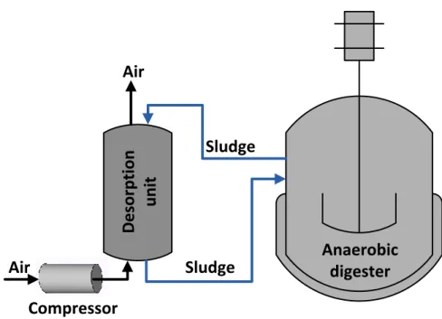
2.2.4. CO2 removal by in-situ desorption 625
Biogas upgrading by in-situ desorption of CO2 is based on the higher aqueous solubility of 626
CO2 compared with CH4. This technology has been implemented on a novel anaerobic 627
digester configuration (Figure 5) consisting of an external desorption unit, interconnected
628
with the anaerobic digester. The anaerobic mixed liquor is continuously recycled to an
629
aerated desorption unit, operated in countercurrent mode. The dissolved CH4, H2S and CO2 630
are easily stripped out from the recycling sludge, which results in an overall decrease in the
631
H2S and CO2 content in the biogas. However, the methane yield is lower as a result of CH4 632
28
the mixed anaerobic liquor (mainly present as bicarbonate) compared to that of CH4 634
support the quasi-selective separation of CO2 in the desorption unit. Lindberg and 635
Rasmuson (2006) identified the air flow rate in the desorption unit as a key operational
636
variable during the evaluation of the performance of this innovative biogas upgrading
637
configuration, using a bubble column as external desorption unit. The higher the air flow
638
rate, the lower the CO2 and H2S content in the upgraded biogas but the higher the CH4 639
losses and the redox potential of the mixed liquor, which surprisingly did not cause any
640
negative effect on the activity of the digester. Longer (but high enough to bring CH4 641
concentration to the set point) sludge residence times in the desorption unit are
642
recommended to maximize CO2 removal from biogas while minimizing methane losses and
643
the N2 content in the biogas. Maximum CH4 concentrations of 87% with associated CH4 644
losses of 8 % and biogas N2 concentrations of 2% (the main biogas pollutant being CO2)
645
were obtained by Nordberg et al (2012) in a pilot scale (15-19 m3) digesters interconnected
646
to 90-140 L desorption units. Likewise, an external hollow fiber membrane (where
647
degassing was driven by vacuum) was interconnected to a lab scale UASB reactor via
648
mixed liquor recycling in a recent study by Luo and co-workers (2014), which resulted in a
649
biomethane with CH4 concentrations of ≈94 % and no disturbance on the COD removal or 650
biogas yield.
651 652
Finally, it should be stressed that the fact that most biological CO2 removal technologies
653
are still in a lab or pilot scale limited the availability of both investment and operating cost 654
data for the technologies discussed in section 2.2. 655
29
3.
Removal of Hydrogen Sulfide
657
Unlike CO2 removal, biotechnologies for biogas desulfurization are nowadays implemented 658
at full scale due to their similar efficiencies and lower operating costs when compared to
659
their physical/chemical counterparts. The following section reviews the most commonly
660
used technologies for H2S removal from biogas nowadays. 661
662
3.1. Physical/Chemical H2S removal Technologies
663
Most physical/chemical technologies available nowadays for biogas desulfurization are
664
conventional unit operations adapted from chemical engineering, which also support the
665
removal of other sulfur biogas contaminants such as mercaptans. In-situ chemical
666
precipitation, adsorption, absorption and membrane separation constitute the most
667
commonly used technologies for H2S removal from biogas. 668
669
3.1.1 In-situ H2S precipitation 670
671
The addition of Fe2+ or Fe3+ in the form of FeCl
2, FeCl3 and FeSO42 into the digester or to 672
the organic feed can efficiently control H2S concentrations in the biogas by in-situ reacting 673
with the H2S in the anaerobic mixed liquor, generating the insoluble salt FeS (equations 4, 674
5) (Petersson and Wellinger, 2009; Ryckebosch et al, 2011):
675 676
Fe2+ + S2- FeS (4)
677
2Fe3+ + 3S2- 2FeS +S (5)
30
This technology is suitable to in-situ remove the H2S biologically produced in the digester 680
at high H2S concentrations, but cannot cost-efficiently reduce H2S levels in the biogas 681
below 100-150 ppmv (Persson et al, 2006). While this technology requires only an iron salt 682
storage tank and a dosing pump as major investment, the high operating costs derived from
683
the purchase of the chemical reagents (≈0.13-0.33 € kg FeCl3-1) represent the main 684
disadvantage of this simple H2S control approach. Thus, operating costs as high as 0.024 € 685
m-3 of biogas have been reported in literature using a FeCl3 dose of 0.035 kg FeCl3/ kg of 686
total sludge solids (Tomàs et al, 2009).
687 688
3.1.2 Adsorption
689
This classical unit operation is based on two parallel adsorbent modules (packed with either
690
Fe2O3, Fe(OH)3, ZnO or activated carbon) operated in an adsorption-regeneration (or 691
alternatively adsorbent replacement) configuration. The high cost associated to the
692
regeneration and replacement of the adsorbent material limits its application to
small-693
medium scale digesters (Abatzoglou and Boivin, 2009).
694 695
Chemical adsorption of H2S into Fe2O3, Fe(OH)3 and ZnO-based filters has become a 696
popular technology based on its simplicity, high efficiency (e.g. ZnO can provide H2S 697
biomethane levels down to 1 ppmv), fast oxidation kinetics (Petersson and Wellinger, 2009; 698
Ryckebosch et al, 2011). The oxidation of H2S and further regeneration of this adsorbent 699
material can be stoichiometrically described as follows (equations 6,7,8):
700 701
Fe2O3 + 3H2S Fe2S3 + 3H2O (6)
702
2Fe(OH)3 + 3H2S Fe2S3 + 6H2O (7)
31
2Fe2S3 + 3O22Fe2O3 + 6S (8)
704 705
These chemical reagents are often immobilized onto wood chips or red mud (a waste from
706
aluminum manufacture) in order to increase the superficial area of the adsorbent, which
707
significantly decreases as a result of aggregation due to biogas water condensation (Persson
708
et al, 2006). The process is operated at gas residence times ranging from 1- 15 min using
709
breakthrough threshold H2S concentrations of ≈ 100 ppmv. Adsorbent regeneration is a very 710
exothermic process which can result in wood chip auto-ignition if temperature is not
711
properly controlled, and can be conducted only 1-2 times based on an empirical loss of
712
adsorption capacity of 33 % per regeneration (Abatzoglou and Boivin, 2009). Commercial
713
adsorbents exhibit an adsorption capacity of 0.2 g H2S per gram of iron wood chips or 1.8-714
2.5 g H2S g Fe2O3-1 under continuous operation with air supplementation (2-3 %) to allow 715
an in-situ adsorbent revivification (Kohl and Neilsen, 1997; McKinsey, 2003; Kapdi et al,
716
2005). The cost of these adsorbents varies from 0.6 to 1.7 € kg-1 (Abatzoglou and Boivin,
717
2009). The high adsorbent costs and replacement frequency, together with the hazardous
718
nature of the saturated material, entail very high operating costs (0.021-0.037 € m3,
719
considering 5 year capital amortization), which constitutes one of the main disadvantage of
720
this technology. On the other hand, the investment costs (only considering the adsorption
721
unit) largely depend on the commercial brand (SulfaTreat®, Sulfur-Rite®, Media-G2®, etc),
722
ranging from 120 to 640 € (m3/h)-1.
723 724
H2S removal can be also carried out using adsorption into non-impregnated, catalytic-725
impregnated, and impregnated activated carbons, the two latter catalyzing H2S oxidation to 726
elemental sulfur (which indeed is the element adsorbed onto the activated carbon) at higher
32
rates (Persson et al, 2006; Abatzoglou and Boivin, 2009). Catalytic impregnation is
728
conducted by treating the carbon with a nitrogen containing reagent such as urea or
729
ammonia, while regular impregnation requires mixing of the carbon (before, during or after
730
activation) with NaHCO3, Na2CO3, NaOH, KOH, KI or KMnO4. H2S adsorption is 731
performed at high pressure (7-8 bar) and temperature (50-70ºC) with addition of air to the
732
biogas at 4-6 % in order to support the partial oxidation of H2S (equation 9) (Ryckebosch 733
et al, 2011):
734 735
2H2S + O22S + 2H2O (9)
736 737
Only KI or KMnO4 impregnation supports the partial oxidation of H2S in the absence of 738
O2. Carbon impregnated with these compounds is the preferred option for desulfurization 739
when biomethane is to be injected in natural gas grids or used as a vehicle fuel (Petersson
740
and Wellinger, 2009). Despite the elemental sulfur adsorbed can be desorbed at high
741
temperatures, in most cases the saturated activated carbon bed is replaced rather than
742
regenerated (Rutledge, 2005). Catalytic, impregnated and non-impregnated carbons exhibit
743
maximum adsorption capacities of 0.1, 0.15 and 0.2 g H2S g carbon-1, respectively. The 744
mechanisms underlying H2S oxidation are highly sensitive to the chemical properties of the 745
activated carbon surface, with acidic surfaces promoting H2S oxidation to SO2 and H2SO4, 746
and alkaline surfaces boosting the production of elemental sulfur (Bandosz, 2002). In
747
addition, the presence of water in the biogas severely deteriorates the performance of H2S 748
removal since this biogas component reacts with CO2, forming carbonates, and promotes 749
the formation of sulfurous acid, which can deactivate the active catalytic sites. Finally,
750


![Figure 6. EFFLUENTBIOGAS SRBHS-(d) H 2 S (d) S-organic, SO 4 2-FEED H 2 S (g) S 0 (s) EFFLUENTH2 S FREE BIOGASSRBHS-(d)H2S(d)S-organic, SO4 2-FEED H 2 S (g) SOBAIR / O2 G-L interphase [H 2 S (g) ] [H 2 S (d) ] + [HS -(d) ] Bulk gas-phase Bulk liquid-pha](https://thumb-us.123doks.com/thumbv2/123dok_es/5981208.167527/77.918.133.779.180.898/figure-effluentbiogas-organic-effluenth-biogassrbhs-organic-sobair-interphase.webp)

![(WSNs)[ ].RFIDidentifiesanobject(forexample,avehicle)usingauniqueidentifier ],withauniqueidentityandtheabilitytosenseandcollectinformationfromthesurroundingenvironment,andshare ].Therefore,trafficcongestionhasbecomeafundamentalproblemandamajorchallengeformos](data:image/gif;base64,R0lGODlhAQABAIAAAP///wAAACH5BAEAAAAALAAAAAABAAEAAAICRAEAOw==)