An Efficient QoS Routing Protocol for Mobile
Ad-Hoc Networks
⋆Inwhee Joe
College of Information and Communications, Hanyang University, Seoul, Korea
Summary. To satisfy the user requirements for continuous and real-time multime-dia information, the concept of Quality of Service (QoS) has emerged as a main issue in mobile ad-hoc networks. QoS routing is to find a route according to the QoS re-quirements of the users. In this paper, we propose an efficient QoS routing protocol that is based on AODV over TDMA, one of the typical routing protocols for mobile ad-hoc networks, by making a bandwidth reservation for QoS guarantee. While the existing schemes calculate the maximum available bandwidth for each candidate path, our scheme is to check only if the bandwidth of a given path satisfies the end-to-end QoS requirement. Also, the key idea in the bandwidth reservation is to select carefully time slots without causing any conflicts in the wireless environment, thereby maximizing the bandwidth efficiency. In order to evaluate the performance of the proposed QoS routing protocol, some simulations are carried out in the ad-hoc environment. The simulation results show that the proposed protocol provides sufficiently low and stable delay performance regardless of the offered load.
1 Introduction
In recent years, wireless mobile networks have become increasingly important for users of computing systems. There are currently two types of wireless mo-bile networks: Infrastructured network and Ad-hoc network. The first type refers to a network with any infrastructure by installing base stations in cel-lular networks or access points in wireless local area networks. On the other hand, the second type of wireless mobile networks does not rely on any fixed infrastructure. This may happen on conferences, rescue operations, or military actions in enemy terrain, i.e., when mobile users need to communicate to each other in situations and places with no infrastructure where rapid deployment of a network is required on a temporary basis.
Mobile ad-hoc networks consist of mobile nodes (each node conceptually consisting of a router, a radio port and one or more host computers). To communicate with mobile nodes that are not within the transmission range, a routing protocol is required for each node. Recently, many routing proto-cols have been proposed for mobile ad-hoc networks. In general, they can be divided into two main categories: proactive and reactive protocols. In a proac-tive routing protocol, nodes periodically exchange routing information with other nodes to maintain all the routes on the network beforehand, while in a reactive approach each node attempts to discover a route on demand only when it has data to send. Although there is no single standard routing proto-col yet, reactive routing protoproto-cols are known to perform better than proactive routing protocols in terms of lower overheads. Typical examples of reactive routing protocols include the dynamic source routing (DSR) protocol and the ad-hoc on-demand distance vector (AODV) routing protocol.
Even if existing routing protocols are designed to cope well with the dy-namic change of network topology, they are mainly concerned with best-effort data traffic. The problem of Quality-of-service (QoS) routing to support mul-timedia traffic over mobile ad-hoc networks is studied here. The goal of QoS routing is to find a route from a source to a destination that satisfies the end-to-end QoS requirements such as bandwidth and delay. Unlike traditional wireless networks, providing QoS is more difficult for mobile ad-hoc networks, because the network topology changes frequently and the end-to-end route is a multi-hop wireless path.
QoS routing in mobile ad-hoc networks has recently started to receive increasing attention in the literature [3, 4, 5]. To find out a route to the destination, QoS routing normally calculates the maximum available band-width for each candidate route so that it can check if the bandband-width meets the end-to-end QoS requirement. In fact, the ability to provide QoS is heav-ily dependent on how the resources like bandwidth are managed at the MAC (Medium Access Control) layer, whether it is TDMA (Time Division Multiple Access) or CDMA (Code Division Multiple Access). In TDMA, calculating the maximum bandwidth for a given multi-hop route is proven to be NP-complete because of the interference problem [1]. Some use CDMA on top of TDMA to eliminate this problem by assigning a different code to each transmitter [1].
2 Bandwidth Calculation
In the packet-switched network, QoS is meaningful only for a flow of packets between the source and destination. So, it is assumed that the application is flow-based and requires constant bandwidth as the end-to-end QoS require-ment to support multimedia traffic over mobile ad-hoc networks. Since band-width guarantee is one of the most critical requirements for multimedia traffic, we only consider bandwidth as the QoS here. In an attempt to satisfy the QoS requirement, the network must ensure that adequate network resources like bandwidth are available for the entire duration of a given flow. Therefore, QoS guarantees can be delivered only with appropriate resource reservation mechanisms. For each flow, QoS routing is the process of finding the route that meets the required bandwidth. In TDMA, the bandwidth is expressed in terms of time slots.
To find a route with sufficient bandwidth, QoS routing normally calculates the maximum available bandwidth for each candidate route, and then make a reservation along the route if the bandwidth is large enough to meet the QoS requirement as a part of the process. In this case, both the hidden terminal and exposed terminal problems should be taken into account so that the interference can be avoided in the wireless environment. If a given route R provides a bandwidth of B time slots, it means that every link along the route has at least B available time slots, and these slots do not interfere with other transmissions. That is, the end-to-end bandwidth of a route is not determined just by the bandwidth of the bottleneck link, because mutual interference among available time slots of links should be considered in the wireless environment.
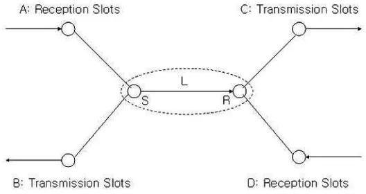
Each transmission is organized in a frame that contains a fixed number of time slots, N. The entire network is synchronized on a frame and slot ba-sis. The link bandwidth can be defined as the number of free time slots on the link from the sender to the receiver without any conflicts to other trans-missions. It is different according to the link direction, because the conflicts are directional. Due to the hidden-terminal and exposed-terminal problems, the link bandwidth is affected only by transmission or reception activities of one-hop neighbor nodes from the sender and the receiver. The available link bandwidth from a sender S to a receiver R can be obtained in terms of free time slots by removing the following unavailable time slots from the total time slots N:
• Time slots that are used already by a sender S or by a receiver R
• Time slots that are used to receive in one-hop neighbor nodes of a sender
S
• Time slots that are used to send in one-hop neighbor nodes of a receiver
R
and a receiver node R are regarded as one super node, the scope of our interest is one-hop range of the super node, since the link bandwidth is affected only by transmission and reception activities of the one-hop neighbor nodes. On the sender’s side, there are two cases whether time slots are used for transmission or reception. First, node A has only reception slots, and these slots cannot contribute to the link bandwidth L because of the hidden-terminal problem. Second, node B has only transmission slots, and these slots can contribute to the link bandwidth L because of the exposed-terminal problem. On the receiver’s side, there are also two cases depending on the direction. Node C has only transmission slots, and these slots cannot be counted into the link bandwidth L because of the hidden-terminal problem. Finally, node D has only reception slots, and these slots can be counted into the link bandwidth L, because they don’t interfere with the transmission from S to R. In summary, the link bandwidth L can be calculated by counting the number of remaining time slots in the total slots N, after removing the slots that are used by the sender S and receiver R, also used by their neighbor nodes A & C.
Fig. 1. Link Bandwidth Calculation
bandwidth, we propose only to check if the bandwidth of a given route satisfies the end-to-end QoS requirement.
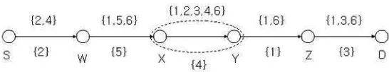
[image:5.612.150.423.300.351.2]Once every link bandwidth on the route is calculated in terms of free time slots, then the next step is what slots to choose for the path bandwidth without any conflicts to each other. Due to the hidden-terminal and exposed-terminal problems, the link bandwidth is affected only by one-hop neighbor nodes of the sender and the receiver. It means that for slot selection the path bandwidth should consider all the slots until the two-hop links with the sender and receiver in the center. For example, when slots are chosen for the path bandwidth from node X to Y, both its one-hop and two-hop links should be taken into account, as shown in Fig. 2. In this case, there are two one-hop links from node W to X and from node Y to Z. Also, there are two two-hop links from node S to W and from node Z to D. The difference between the left links and the right links around this link from node X to Y is that the left links already have their slots chosen according to the end-to-end QoS requirement. In particular, Fig. 2 illustrates how slots are selected along the route as the
Fig. 2.Slot Selection for Path Bandwidth
Fig. 3. Slot Selection Algorithm
3 QoS Routing with Bandwidth Reservation
3.1 Hello Message
Each node broadcasts a Hello message on a periodic basis to its one-hop neighbor nodes. The Hello message contains the time slot information ex-tracted from the slot table of each node that maintains which time slots are used for transmission or reception, and which time slots are available. Also, the Hello message contains the time slot information of the one-hop neighbor nodes using the previous Hello messages received from the neighbor nodes. In the Hello message, the sequence number is used to identify which message is more up-to-date. In this way, each node collects the time slot information of all the neighbor nodes in its two-hop range using the periodic Hello messages. As a result, the link bandwidth can be calculated with such information for each link direction, as mentioned in Section 2.
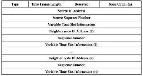
[image:7.612.146.426.337.487.2]Fig. 4 shows the modified Hello message format. One part of the previous Reserved field in the original Hello message is renamed as the field of Time Frame Length to indicate the total number of time slots for each frame cycle. The Node Count field indicates the total number n of the one-hop neighbor nodes. For each node, the IP address, sequence number, and the time slot information are included in the Hello message. As mentioned earlier, the time slot information represents the current state of each time slot, i.e. which slots are in use for transmission or reception, and which slots are available.
Fig. 4.Hello Message
3.2 Bandwidth Reservation
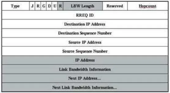
nodes like AODV. As the RREQ message proceeds hop by hop until the des-tination, each intermediate node appends the link bandwidth information to the RREQ message. The link bandwidth is a list of free time slots for each directional link and this information can be obtained using the periodic Hello messages. Once the RREQ message reaches the destination, the destination node extracts all the link bandwidth information between source and desti-nation out of the RREQ message. With this, our slot selection algorithm is applied so that it attempts to choose time slots for each link along the path according to the end-to-end QoS requirement. If the algorithm cannot find the required number of available time slots from each link, the destination node generates no response because this particular route does not meet the end-to-end QoS requirement.
Fig. 5.Route Request Message
Fig. 5 shows the modified RREQ message. In comparison with the original RREQ message, the modified portion is shaded. The R flag indicates whether the QoS guarantee is required or not, depending on the user requirement. The LBW Length field indicates the total number of time slots for each frame cycle. A directional link consists of two nodes, the transmitter node and the receiver node. The first link starts from the source node as a transmitter. Thus, for each link the IP address of the receiver node and the link bandwidth information are added to the last part of the RREQ message, as long as the R flag is set. This process continues on a hop by hop basis until the destination.
be unicast from the destination along the path to the source just like AODV. Whenever the RREP message is received, each relay node makes a bandwidth reservation using the selected time slot information of the message. In other words, as indicated in the selected time slot information of the RREP mes-sage, the corresponding time slots will be reserved for each node to support this particular flow.
[image:9.612.145.426.231.356.2]Finally, the source node begins to transmit data through the reserved path. Fig. 6 shows the modified RREP message. In comparison with the original RREP message, the modified portion is shaded. The same R flag is used here for QoS requirement. The Selected Slot Number field indicates the number of the time slots selected. The time slot information of each link is expressed in a form of the bit map: Selected Bitmap. This information represents which slots are selected as the path bandwidth for each link along the route from the source to the destination.
Fig. 6.Route Reply Message
4 Simulation
The objective of simulation is to evaluate the performance of our QoS rout-ing protocol with bandwidth reservation for mobile ad-hoc networks. Since the network simulatorns−2 does not support TDMA for mobile ad-hoc networks,
set to 20. Given simulation parameters above, we measure the QoS guarantee ratio and the delay performance as a function of the offered load.
Fig. 7. QoS Guarantee Ratio
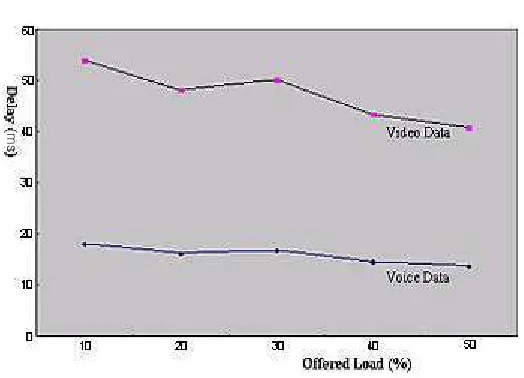
Fig. 8.Delay Performance
[image:10.612.154.416.323.512.2]For the video traffic the curve drops dramatically, while it drops gradually in case of the voice traffic. Since more time slots are required for the video traffic, it explains the behavior of the video curve in terms of the QoS guarantee ratio as compared to the voice case. To support video traffic, four time slots are required for transmission and another four time slots are required for reception at the same time, thereby leading to eight time slots for each relay node. As a result, it is certain that the video curve drops rapidly with the increased offered load, in that the total number of time slots is only 20 for each frame cycle.
On the other hand, Fig. 8 presents the delay performance as a function of the offered load. The delay performance is defined as the end-to-end de-lay measured at the application de-layer from the source to the destination. Regardless of the offered load, it is shown that the delay is sufficiently low and stable for both cases. It ensures that our proposed QoS routing protocol works correctly to make a bandwidth reservation with the slot selection al-gorithm according to the end-to-end QoS requirement. Obviously, the video traffic causes more delay than the voice traffic. If the offered load is 60% or higher, the QoS guarantee is actually hard to deliver, so measuring the delay is not so useful at all. In summary, the simulation results show that the de-lay performance is very stable and low enough to satisfy the end-to-end QoS requirement regardless of the offered load.
5 Conclusions
In this paper, we have discussed the design and performance of a novel QoS routing protocol with bandwidth reservation for mobile ad-hoc networks. While the existing schemes calculate the maximum available bandwidth for each candidate path, our scheme is to check only if the bandwidth of a given path satisfies the end-to-end QoS requirement. In fact, finding the maximum path bandwidth for a given route is proven to be NP-complete in terms of global optimization. Instead of calculating the maximum path bandwidth, we propose only to check if the path bandwidth meets the end-to-end QoS re-quirement by applying our slot selection algorithm. The algorithm attempts to choose carefully time slots without causing any conflicts in the wireless environment, thereby maximizing the bandwidth efficiency. If it can find the required number of available time slots for each link along the path, it ensures that the path bandwidth meets the end-to-end QoS requirement.
References
1. C.R. Lin and J. Liu, “QoS Routing in Ad Hoc Wireless Networks,” IEEE Jour-nal on Selected Areas in Communications, Vol. 17, No. 8, pp. 1426-1438, August 1999.
2. C. Perkins, E. Belding-Royer, and S. Das, “Ad Hoc On-Demand Distance Vec-tor (AODV) Routing,” IETF RFC 3561, July 2003.
3. W. Liao, Y. Tseng, and K. Shih, “A TDMA-based Bandwidth Reservation Protocol for QoS Routing in a Wireless Mobile Ad Hoc Network,” Proceedings of IEEE International Conference on Communications, pp. 3186-3190, April 2002.
4. Q. Xue and A. Ganz, “Ad Hoc QoS On-Demand Routing in Mobile Ad Hoc Network,” Journal of Parallel and Distributed Computing, Vol. 63, pp. 154-165, February 2003.
5. C. Zhu and M.S. Corson, “QoS Routing for Mobile Ad Hoc Networks,” Pro-ceedings of IEEE INFOCOM, pp. 322-331, June 2002.
6. I. Joe, “Reservation CSMA/CA for QoS Support in Mobile Ad Hoc Networks,” Lecture Notes in Computer Science, Vol. 3842, pp. 231-235, January 2006. 7. I. Joe and S.G. Batsell, “MPR-based Hybrid Routing for Mobile Ad Hoc
Net-works,” Proceedings of IEEE Conference on Local Computer Networks, pp. 7-12, November 2002.