All fiber tunable optical delay line
8
0
0
Texto completo
(2) 13. C. Caucheteur, S. Bette, R. Garcia-Olcina, M. Wuilpart, S. Sales, J. Capmany, and P. Mégret, “Transverse strain measurements using the birefringence effect in fiber Bragg gratings,” Photon. Technol. Lett. 19(13), 966–968 (2007). 14. D. Wang, M. Matthews, and J. Brennan Iii, “Polarization mode dispersion in chirped fiber Bragg gratings,” Opt. Express 12(23), 5741–5753 (2004), http://www.opticsinfobase.org/oe/abstract.cfm?URI=oe-12-23-5741. 15. C. Wang, and J. Yao, “Fourier Transform ultrashort optical pulses shaping using a single chirped fiber Bragg grating,” Photon. Technol. Lett. 21(19), 1375–1377 (2009).. 1. Introduction Tunable optical delaying is a valuable function in optical telecommunication networks since it enables important applications such as buffering, packet synchronisation or jitter control [1]. Tunable optical delay lines also find applications in optical coherence tomography [2] and phased array antennas [3]. Among the different ways investigated to achieve tunable optical delays, the use of linearly chirped fiber Bragg gratings (CFBGs) as dispersive elements has attracted considerable attention because of its simplicity and good performances. Such gratings are characterized by a linear group delay evolution within their reflection band [4]. In practice, the time delay experienced by pulses is generally tuned either by varying the wavelength of the optical carrier [5,6] or by shifting the CFBG resonance band through thermal or mechanical actuation [7,8]. Because wavelength shifts are induced in these experiments, optical pulses with a linewidth comparable to that of the CFBG reflection band cannot be variously delayed without undergoing important distortions. This is particularly detrimental, especially in the framework of high speed transmissions with bit rates higher than a few tens of Gbits/s. In addition, these solutions require a second CFBG perfectly matched with the first one to compensate its chromatic dispersion [9,10]. In this work, we have developed a novel setup able to generate a tunable delay with a single CFBG written into a standard single mode fiber. Instead of using directly the CFBG group delay curve, our solution exploits the differential group delay (DGD) evolution. In the proposed setup, orthogonally polarized pulses are sent through both ports of the CFBG while its local birefringence is controlled. This leads to a dynamic evolution of the DGD inside the CFBG reflected bandwidth so that tunable delays can be achieved. Two significant advantages are therefore obtained. Contrary to previous works [5–8,11], our setup does not require any wavelength shift. Consequently, the full CFBG bandwidth can be used to delay optical pulses nearly as broad as the grating reflection band. In addition, the double pass of light inside the same CFBG (in both directions) allows to compensate the second-order chromatic dispersion, without the need for a second CFBG perfectly matched with the first one. This simplifies the implementation and significantly alleviates potential impairments due to a mismatch between both gratings. The performances of our setup are experimentally investigated with a linearly polarized pulsed laser source at 1548 nm, characterized by a pulse duration of 6.3 ps and a spectral width of 64 GHz at full width at half maximum (FWHM). We experimentally demonstrate that optical delays continuously tunable up to 20 times the pulse duration can be achieved with this setup by applying a mechanical stress on the CFBG. The remaining of the paper is organized as follows. Section 2 recalls the spectral features of CFBGs in the presence of birefringence. Section 3 presents the advantages of our experimental setup for delaying optical pulses without dispersion, and its experimental demonstration. Finally, section 4 focuses on the tunability of the delay line. 2. CFBGs spectral characteristics in the presence of local birefringence CFBGs present an index modulation period of a few hundreds of nanometers. The periodicity varies along the fibre at a rate C (also called chirp coefficient) that can reach several nm/cm. At a location z along a CFBG, light is reflected at the wavelength λ(z) = 2neffΛ(z) where neff is the fiber core effective refractive index and Λ(z) is the index modulation periodicity at the position z (Λ(z) = Λ0 + Cz). As a result, the group delay curve monotonically evolves in the reflection band, starting from zero (a maximum value) and reaching a maximum value (zero) #118768 - $15.00 USD. (C) 2010 OSA. Received 19 Oct 2009; revised 18 Dec 2009; accepted 20 Dec 2009; published 28 Jan 2010. 1 February 2010 / Vol. 18, No. 3 / OPTICS EXPRESS 3094.
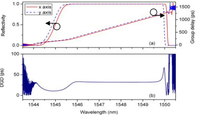
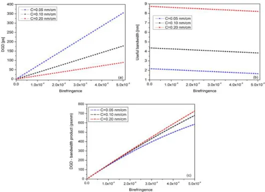
(3) at the end of the grating when the light is injected through the short (long) wavelengths port. Hence, the group delay evolutions as a function of the wavelength are of opposite signs when the light is injected from both ports of the CFBG. In the presence of local birefringence, the effective refractive indices of the two orthogonal polarization modes, defined along the x and y axes, can be expressed as neff,x = neff + Δn/2 and neff,y = neff-Δn/2. These modes undergo different couplings through the grating so that two different reflected coefficients are obtained. The x and y modes reflected spectra are identical in shape but slightly shifted in wavelength by a quantity Δλ = 2ΔnΛ [12]. An important consequence of the birefringence is the presence of a significant differential group delay (DGD) between the two eigenmodes. It is defined as the difference in absolute values between the delays measured along the x and y axes [12]: DGD(l) =| t x (l) − t y (l) |. (1). where τx (resp. τy) is the group delay of the x (resp. y) mode. Figure 1(a) depicts the simulated amplitude and group delay responses of a CFBG obtained from the coupled mode theory [4] in the presence of birefringence, for two orthogonally polarized axes. The parameters were chosen to match those of the experimental grating used in section 3, with a core refractive index modulation δn of 4 × 10⁻⁴ and a birefringence Δn set to 8 × 10⁻⁵. The DGD curve is displayed in Fig. 1(b). A remarkable feature is the flatness of the DGD in a band slightly smaller than the full CFBG reflection band. This band roughly corresponds to the CFBG reflected bandwidth reduced by the quantity Δλ (this quantity increases with the birefringence value). It is called useful bandwidth in the following.. Fig. 1. (a) Simulated reflected amplitude and group delay spectra of a CFBG in the presence of birefringence for two orthogonally polarized axes (solid and dashed lines). (b) Associated DGD curve (parameters used for the simulation: L = 15 cm, Λ0 = 531.5 nm, C = 0.12 nm/cm, δn = 4 × 10⁻⁴ and Δn = 8 × 10⁻⁵).. The dynamic evolution of the DGD through the modification of the local CFBG birefringence is the main feature of the experimental setup presented in the following sections. In practice, the local birefringence can be controlled by transversally loading the CFBG [13]. As a consequence, the DGD value can be modified dynamically. Moreover, depending on the aimed application, the DGD evolution can be further optimized thanks to the CFBG physical parameters. As demonstrated in Ref [14], the chirp coefficient C has the most significant impact on the DGD value. Figure 2(a) shows simulation results illustrating the dependence of DGD versus birefringence, for three different values of chirp coefficient C. It can be seen that the DGD increases linearly with the birefringence value. In particular, it reaches several hundreds of picoseconds for a realistic birefringence values in the order of 5 × 10⁻⁴, and chirp coefficient of 0.05 nm/cm. Note that the chosen set of parameters (L, C and Δn) is such that. #118768 - $15.00 USD. (C) 2010 OSA. Received 19 Oct 2009; revised 18 Dec 2009; accepted 20 Dec 2009; published 28 Jan 2010. 1 February 2010 / Vol. 18, No. 3 / OPTICS EXPRESS 3095.
(4) the flat DGD region remains important enough for most applications (more than 1.5 nm in the most stringent case), as shown in Fig. 2(b). This demonstrates that, in the frame of high speed communications (100 Gbits/s for instance), tunable delays of several tens times the pulse duration could be easily reached. However, a compromise must be found between the maximum available DGD and the corresponding available bandwidth, depending on the application requirements. This is illustrated in Fig. 2(c), which shows that the product of DGD with useful bandwidth is almost independent of C, for realistic birefringence values.. Fig. 2. (a) DGD evolution vs. birefringence for 15 cm CFBGs characterized by different chirp coefficients, (b) useful bandwidth evolution and (c) corresponding DGD-bandwidth product.. 3. Operating principle of the experimental setup Figure 3 depicts the schematic of the experimental setup that we developed to experimentally test the dispersionless properties and tunability of our delay line.. Fig. 3. Schematic of the experimental set-up. The optical paths followed by the orthogonally polarized pulses are represented in different colours (red and blue).. In order to demonstrate the performances of this setup in the context of high bit rate transmissions, we used a passively mode-locked fiber laser delivering linearly polarized #118768 - $15.00 USD. (C) 2010 OSA. Received 19 Oct 2009; revised 18 Dec 2009; accepted 20 Dec 2009; published 28 Jan 2010. 1 February 2010 / Vol. 18, No. 3 / OPTICS EXPRESS 3096.
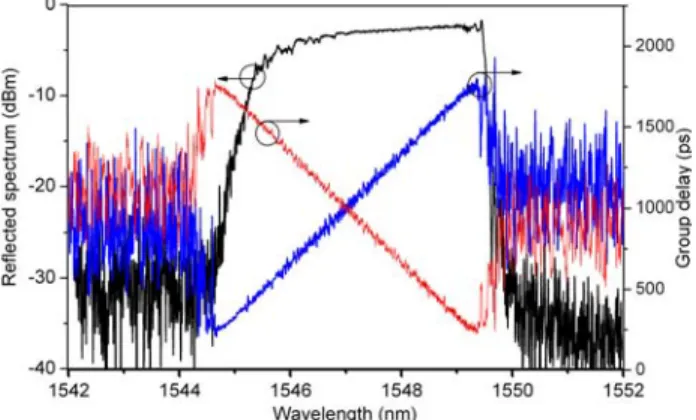
(5) Fourier transform limited pulses of 6.3 ps duration at FWHM at 1548 nm. Note that the pulse characteristics of this laser are similar to the bit slot duration of non-return to zero (NRZ) signals modulated at about 60 Gbits/s. Experiments were carried out on a 15 cm long apodized CFBG whose physical parameters match those used in the simulations in the previous section. The grating has been written in a hydrogen-loaded standard single mode fiber by means of a frequency-doubled argon laser at 244 nm and the scanning-beam phase mask technique. The measured reflection spectrum and group delay curves measured from both ports are displayed in Fig. 4. The refractive index modulation profile of the CFBG is apodized to reduce the ripple on the group delay curve. This results in group delay variations of less than 5% in the CFBG reflection bandwidth.. Fig. 4. Reflected amplitude spectrum (black) and associated group delay evolutions (short wavelengths port (blue) – long wavelengths port (red)) of the used CFBG.. The pulses delivered by the picosecond oscillator are launched into the short wavelengths port of the CFBG (port A) through a polarization controller (PC1) and an optical circulator. Figure 5 shows second-order autocorrelation traces of input (black line) and single-reflected (red line) pulses. Assuming a Gaussian shape, we found that the FWHM of input pulses is 6.4 ps, in good agreement with the data from the source manufacturer. As expected, it can be seen from Fig. 5 that the single-reflected pulses exhibit a significant temporal broadening due to the important chromatic dispersion induced by the CFBG (~350 ps/nm). Since our autocorrelator did not allow us to measure their FWHM, we deduced it from the CFBG group velocity dispersion parameter (β2 = 4.45 10−21 s2/m), and found a value of 108.8 ps. Singlereflected pulses then pass through a second polarization controller (PC2) and are redirected, via a second circulator, to the long wavelengths port of the grating (port B). The blue line of Fig. 5 corresponds to the autocorrelation trace of double-reflected pulses. This trace is quasi identical to the input pulse one, the discrepancy on the FWHM being only 5%. It is worth noting that the temporal broadening obtained in the single reflection case is only due to dispersion effects and not to spectral narrowing due to the finite bandwidth of the reflected band of the CFBG. All these measurements allow to validate the dispersion compensation function of our setup, similarly to the one presented in Ref [15]. However, the main difference between our setup and the one of Ref [15]. concerns the control of polarization effects. Our setup contains two polarization controllers that simultaneously play two crucial roles. At first, they allow to align the polarisation state of the injected (resp. reflected) signal along the x (resp. y) axis of the CFBG. Hence, the pulses are oriented along the x axis at the port A so that the reflected pulses experience a delay fixed by τx. The polarization state of the reflected pulses is then rotated so that the pulses re-enter the grating at the port B, this time aligned along the y axis. Hence, the double-reflected pulses undergo an additional delay corresponding to the DGD induced by the CFBG. The polarization controllers combined with the polarizer-analyzer placed at the output of the setup achieve a second important function. As the DGD is obtained for orthogonally polarized pulses, the setup also avoids the crosstalk #118768 - $15.00 USD. (C) 2010 OSA. Received 19 Oct 2009; revised 18 Dec 2009; accepted 20 Dec 2009; published 28 Jan 2010. 1 February 2010 / Vol. 18, No. 3 / OPTICS EXPRESS 3097.
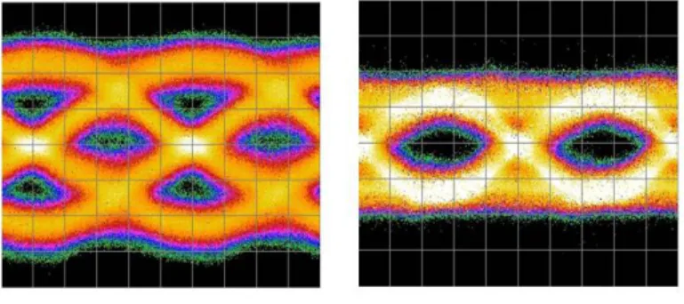
(6) between the transmitted and double-reflected pulses. Indeed, since the grating is not perfectly 100% reflective, a small part of the pulses launched in the port A is transmitted and could interfere with signals going out of the setup. The polarizer-analyzer (a polarizing beam splitter could also be used) placed behind the second circulator is then oriented to isolate the useful signal (pulses reflected twice by the grating) from the transmitted one passing directly through the CFBG and the two circulators. Let us also mention that, since the CFBG orthogonal polarization modes are constant, the orientation of the polarization controllers remains the same whatever the birefringence value.. Fig. 5. Autocorrelation traces of the original pulse (black line), single-reflected pulse (red line) and double-reflected pulse (blue line).. To further confirm the ability of the proposed system to compensate the CFBG chromatic dispersion in the context of data transmissions, a tunable laser source centred around 1548 nm is externally modulated at 10 Gb/s using an intensity modulator. The latter is driven by the pseudo-random binary sequence (PRBS – 2^(31)-1) emitted by a BERTScope S analyzer which is used for eye diagram measurements. Figure 6 depicts the eye diagrams obtained with the single-(left) and double-reflected pulses (right). Due to the pulse spreading, a strong intersymbol interference (ISI) occurs and the eye is completely closed in the single reflection case (left panel). After the second pass in the CFBG, the eye becomes well open, which testifies that the chromatic dispersion is well compensated. Note that, on the right panel, the measurement is quite noisy because of the limited sensitivity of the available photoreceiver. This, however, does not call into question the feasibility demonstration of our setup.. Fig. 6. Eye diagram measured at 10 Gb/s with single-reflected pulses (left) and double-reflected pulses (right). Legend: 20 ps/division (x-axis), 25 mV/division (y-axis).. #118768 - $15.00 USD. (C) 2010 OSA. Received 19 Oct 2009; revised 18 Dec 2009; accepted 20 Dec 2009; published 28 Jan 2010. 1 February 2010 / Vol. 18, No. 3 / OPTICS EXPRESS 3098.
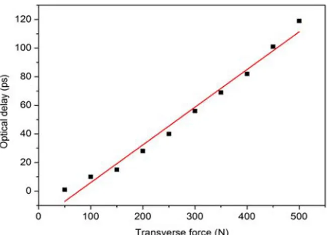
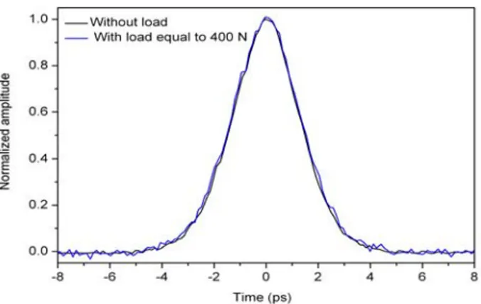
(7) 4. Demonstration of the delay line tunability As numerically shown in section 2, the DGD of the CFBG can be used to tune the optical delay through the modification of the local birefringence. For that purpose, the CFBG was placed in a mechanical system allowing the modification of the local birefringence by the application of controlled transverse forces, as previously reported in Ref [13]. Using an automated translation stage, such a control can be realized at frequencies of less than 1 kHz. The tunable delay generated by the loaded CFBG was measured by means of cross-correlation measurements using a free-space interferometer. Taking into account the uncertainty induced by the precision of the translator, the time delay resolution offered by the measurements is 0.07 ps. Figure 7 depicts the evolution of the optical delay undergone by the output pulses as a function of the transverse force applied on the CFBG. The delay increases with transverse load in a quasi-linear way (red fit). In particular, a nearly 120 ps delay (corresponding to about 20 times the pulse duration) is obtained for a transverse force of 500 Newtons.. Fig. 7. Induced optical delay on the double reflected pulses as a function of the transverse force applied on the CFBG (input pulses at 1548 nm). Squares: experimental measurements, red line: linear fit.. The frequency response of our tunable delay line has also been investigated. Since the pulses are Gaussian and Fourier transform limited, they are characterized by a spectral width of about 0.55 nm at FWHM. This is well below the bandwidth available for delaying without distortion provided by the used CFBG. Indeed, for the highest induced birefringence value, the wavelength spacing between the x and y modes is equal to about 400 pm, which implies a flat DGD region of more than 3 nm inside the CFBG reflection band. The central wavelength of the pulses was thus tuned in the CFBG reflection band and optical delay measurements were made for several different wavelengths. The same behaviour as the one of Fig. 7 was observed (not shown here), which confirms that the performances of the optical delay line are constant for almost all reflected wavelengths. It has finally been checked out that the dispersionless properties of the setup were not altered by the uniform mechanical stress applied to control the optical delay. Figure 8 presents a comparison between the autocorrelation traces measured after a double pass inside the unloaded CFBG and the CFBG loaded with a uniform transverse force of 400 Newtons. One can see that the transverse force does not modify the autocorrelation trace, which means that the pulse duration remains unchanged.. #118768 - $15.00 USD. (C) 2010 OSA. Received 19 Oct 2009; revised 18 Dec 2009; accepted 20 Dec 2009; published 28 Jan 2010. 1 February 2010 / Vol. 18, No. 3 / OPTICS EXPRESS 3099.
(8) Fig. 8. Autocorrelation traces of double reflected pulses after propagation through the unloaded CFBG (black curve) and the CFBG transversally loaded with a force of 400 N (blue curve).. 5. Conclusion In conclusion, we have demonstrated the feasibility of a dispersionless tunable optical delay line that could be dedicated to high bit rates transmission systems. Our configuration is based on a double pass of light in both directions of a CFBG and a simultaneous control of the local birefringence. A variable delay corresponding to the CFBG differential group delay is generated. As the mean DGD is flat inside the CFBG reflection band, our solution is suited to delay pulses covering most of the reflected wavelengths, without dispersion and distortion, which was not possible in previous setups involving wavelength shifts. Theoretical computations have shown the possibility to generate delays as high as a few hundreds of picoseconds. Using a 15 cm long apodized CFBG, tunable delays reaching 120 ps have been experimentally reported. Our solution is thus particularly well suited to delay picoseconds pulses. These results demonstrate that the proposed configuration is an efficient tunable optical delay line. It makes use of passive optical components that does not drastically affect the power budget: the output pulse power has been measured 2.8 dB smaller than the injected pulse. Note that the insertion losses of the whole setup are very low since they are limited by the ones of the circulators. As shown by the simulations, the higher the dispersion, the higher the maximum delay. However, a high dispersion leads to a reduction of the CFBG bandwidth so that amplitude distortions can occur. As our solution is dedicated to high bit rate optical networks, the correct FWHM of the reflection band is a few nanometers. In this case, the reported experiments confirm that the maximum tunable delay value can readily reach more than 100 ps. Let us finally mention that the same configuration could be used as an all-fiber chirped pulse amplification system by inserting an amplifier after the second polarization controller. Acknowledgments Christophe Caucheteur is supported by the Fonds National de la Recherche Scientifique (F.R.S.-FNRS). The authors acknowledge the Attraction Pole Program IAP 6/10 of the Belgian Science Policy (photonics@be), the “Conseil Régional Nord Pas-de-Calais” and the “Fonds Européens de Développement Economique des Régions”. They are indebted to Marc Leparquier for help during autocorrelation measurements.. #118768 - $15.00 USD. (C) 2010 OSA. Received 19 Oct 2009; revised 18 Dec 2009; accepted 20 Dec 2009; published 28 Jan 2010. 1 February 2010 / Vol. 18, No. 3 / OPTICS EXPRESS 3100.
(9)
Figure
+3
Documento similar
In all cases, it is preferable to delay the procedure until the thrombotic risk is at the most minimal possible; in cases of double antiplatelet therapy, it is possible to ei-
In the preparation of this report, the Venice Commission has relied on the comments of its rapporteurs; its recently adopted Report on Respect for Democracy, Human Rights and the Rule
The optical gap and the Urbach energy have also been evaluated for the co-evaporated samples but, as in the case of the pure materials, the values obtained must be taken just as
In addition to those studies the data used in this report has been used to obtain the monthly variability of clear and usable nights in a year, as well as relevant statistics for
In light of the scarce therapeutic tools currently available to delay the appearance of symptoms or disease progression, we will analyze here the following aspects of ALS to be able
Finally, by exploiting the temporal Talbot effect, DCS can be performed with two trains of optical pulses, as well as control their relative spectral phase by a fine tuning of
The Commission notes the applicant's conviction for having edited, published and distributed various articles and finds, therefore, that there has been an interference with
In the “big picture” perspective of the recent years that we have described in Brazil, Spain, Portugal and Puerto Rico there are some similarities and important differences,
