Monterrey, Nuevo León a
Lic. Arturo Azuara Flores:
Director de Asesoría Legal del Sistema
Por medio de la presente hago constar que soy autor y titular de la obra
", en los sucesivo LA OBRA, en virtud de lo cual autorizo a el Instituto Tecnológico y de Estudios Superiores de Monterrey (EL INSTITUTO) para que efectúe la divulgación, publicación, comunicación pública, distribución y reproducción, así como la digitalización de la misma, con fines académicos o propios al objeto de EL INSTITUTO.
El Instituto se compromete a respetar en todo momento mi autoría y a otorgarme el crédito correspondiente en todas las actividades mencionadas anteriormente de la obra.
Methodology to Design Reconfigurable Manufacturing Systems
Title Methodology to Design Reconfigurable Manufacturing
Systems
Authors Rosas Rangel, Roberto
suggest that new competitive advantages must be created within companies to belong capable to develop customized products and cost effective manufacturing systems. New manufacturing systems are required to create new
generation of manufacturing systems, which must be easy to increase in capacity, easy to update and capable to integrate, new technologies. All this will allow new products launching successfully, as well as any adaptation to the manufacturing system due to changes demand; it will be possible quickly to integrate new functions and
technologies to the new manufacturing systems, and by consequence the capacities of those systems will adjust to the market necessities and changes. This research proposes a systemic methodology to design reconfigurable
manufacturing systems. Reconfigurability is an attribute to develop within companies in order to respond rapidly and cost effective to market demands. The methodology to design manufacturing systems is based on systems engineering life cycle. The methodology is structured in three main phases: Manufacturing System Analysis, Manufacturing System Design and Manufacturing
Operations and Maintenance. Manufacturing systems need a degree of reconfigurability since its design and during the operation. The methodology incorporates Digital
Manufacturing tools to support strongly the manufacturing systems design. Through the use of these tools it is possible to design manufacturing systems in a virtual environment to minimize error production. The case studies reported in this thesis were developed in an Automotive Manufacturer company. The first case is the virtual design of an arc weld cell and the second one is the development of a resistance spot weld cell. Both case studies required to give a level of reconfigurability in product, volume, process and layout.
Discipline Ingeniería y Ciencias Aplicadas / Engineering & Applied Sciences
Item type Tesis
???pdf.cover.sheet .dc.contributor.adv isor???
David Apolinar Guerra Zubiaga, Ph. D.
???pdf.cover.sheet .thesis.degree.disci
???pdf.cover.sheet .thesis.degree.prog ram???
Campus Monterrey
Rights Open Access
Downloaded 18-Jan-2017 07:04:19
SUPERIORES DE MONTERREY
CAMPUS MONTERREY
DIVISIÓN DE INGENIERÍA Y ARQUITECTURA PROGRAMA DE GRADUADOS EN INGENIERÍA
METHODOLOGY TO DESIGN RECONFIGURABLE MANUFACTURING SYSTEMS
TESIS
PRESENTADA COMO REQUISITO PARCIAL PARA OBTENER EL GRADO ACADEMICO DE
MAESTRO EN CIENCIAS
ESPECIALIDAD EN SISTEMAS DE MANUFACTURA
POR:
ROBERTO ROSAS RANGEL
INSTITUTO TECNOLÓGICO Y DE ESTUDIOS
SUPERIORES DE MONTERREY
CAMPUS MONTERREY
DIVISIÓN DE INGENIERÍA Y ARQUITECTURA PROGRAMA DE GRADUADOS EN INGENIERÍA
Los miembros del Comité de Tesis recomendamos que la presente Tesis del Ing. Roberto Rosas Rangel sea aceptada como requisito parcial para obtener el grado académico de
Maestro en Ciencias con especialidad en:
SISTEMAS DE MANUFACTURA
Comité de Tesis
_______________________________ David Apolinar Guerra Zubiaga, Ph. D.
Asesor
___________________________ ______________________________ Alvaro Martínez Soto, M.C. Arturo Molina Gutiérrez, Ph. D.
Sinodal Sinodal
APROBADO
_______________________________ Dr. Federico Viramontes Brown
Director del Programa de Graduados en Ingeniería
Dedicatoria
A Dios, por ser la luz que ilumina mi camino y me permite seguir mis sueños.
A mi adorada Esposa, que con su apoyo, amor y sacrificio alimenta mi espíritu y me llena de entusiasmo para ser cada día mejor.
A mis Padres, que me han dado toda una vida llena de sacrificios, amor, valores y sobre todo por sus vivos ejemplos de entrega incondicional; por su esfuerzo y dedicación en hacerme un hombre de bien.
Agradecimientos
Al Dr. David Guerra, por darme la oportunidad de trabajar en su equipo, guiarme durante el desarrollo de este trabajo y sobre todo por su valiosa amistad.
Al Dr. Arturo Molina, por haberme dado la oportunidad de colaborar en su equipo de trabajo y dejarme aprender de sus experiencias. Por siempre exigir más de mí y hacerme crecer.
Al M.C. Alvaro Martínez, por ser parte de este trabajo, aportar su valiosa experiencia, por su valiosa retroalimentación al desarrollo de este trabajo y por su amistad.
Al M.C. Joaquín Aca, por sus comentarios y retroalimentaciones a este trabajo de tesis, que fueron de un enorme valor al desarrollo de la misma.
Al Dr. Mario A. Martínez, por haberme dado la oportunidad de integrarme al CIDYT y apoyarme en la realización de mi proyecto de maestría.
Al Dr. Guillermo Jiménez, por su apoyo y asesoría en este trabajo de tesis.
A mis grandes compañeros, Natalie, Nicolás, Luis, David Concha, David Cartagena, Choche, Camilo, Mathieu, Pedro, Ricky; por los momentos de desvelo que compartimos.
A Nacho, Andrés, Luis y Ricardo Leal, por su valioso apoyo en las simulaciones. A mis mejores amigos, Polo, Gil, Ricardo Camacho, Andrés, Iván, Roberto Rodríguez, Gerardo, Roberto Delgado; que hicieron de esta experiencia una mina de fraternidad y amistad.
A la Cátedra de Investigación en Mecatrónica del Tecnológico de Monterrey por financiar parte del desarrollo de este trabajo.
SUMMARY
Emerging economies and new ways of doing business are changing the world in a dramatic manner, these changes suggest that new competitive advantages must be created within companies to belong capable to develop customized products and cost effective manufacturing systems. New manufacturing systems are required to create new generation of manufacturing systems, which must be easy to increase in capacity, easy to update and capable to integrate, new technologies. All this will allow new products launching successfully, as well as any adaptation to the manufacturing system due to changes demand; it will be possible quickly to integrate new functions and technologies to the new manufacturing systems, and by consequence the capacities of those systems will adjust to the market necessities and changes.
This research proposes a systemic methodology to design reconfigurable manufacturing systems. Reconfigurability is an attribute to develop within companies in order to respond rapidly and cost effective to market demands. The methodology to design manufacturing systems is based on systems engineering life cycle. The methodology is structured in three main phases: Manufacturing System Analysis, Manufacturing System Design and Manufacturing Operations and Maintenance. Manufacturing systems need a degree of reconfigurability since its design and during the operation.
The methodology incorporates Digital Manufacturing tools to support strongly the manufacturing systems design. Through the use of these tools it is possible to design manufacturing systems in a virtual environment to minimize error production.
Chapter 1. Introduction
1
Introduction
1.1 Background
Emerging economies and new ways of doing business are changing the world in a dramatic manner, these changes suggest that new competitive advantages must be created within companies to belong capable to develop customized products and cost effective manufacturing systems. Manufacturing Industry play a leading role in regional development of Mexican Industry, however, the absence of formal programs for the development of manufacturing systems place to the Mexican Industry in disadvantage respect to other countries. In order to compete, Mexican Companies require adopting formalized process to implement and improve their practices during design of manufacturing systems. On this research thesis a systematic approach is proposed in order to design and configure manufacturing systems Facility Development, independently of the industrial sector.
Global economy and new ways of doing business cause dynamic changes in manufacturing companies. These changes are related to new competitive environment. The Next Generation Manufacturing Companies require improving significantly their technological capacities through internal changes that allow them to respond rapidly to these challenges in order to be successful.
previous, causes the necessity to create a new manufacturing systems that response, in terms of flexibility and adaptability, to the necessities and demands of the market.
According to this, new manufacturing systems are required to create new generation manufacturing systems, which must be easy to climb in capacity, easy to update and capable to integrate, fast and easy, new technologies. All this will allow new products launching in production lines, as well as any adaptation to the manufacturing system due to changes in demand; it will be possible quickly to integrate new functions and technologies to the new manufacturing systems, and by consequence the capacities of those systems will adjust to the market necessities and changes.
1.2 Research justification
Manufacturing companies have new challenges in a globalized and competitive manufacturing environment. To be successful, it is needed to develop new manufacturing systems to accomplish customer’s requirements, which are mainly oriented in low cost and time delivery. This vision suggests considerable changes in manufacturing enterprises. The National Research Council, in last decade, realized a study to define the vision, trends and perspectives for the Next Generation Manufacturing. According to this study manufacturing in 2020 will present six major challenges [NRC, 1998]:
• Grand Challenge 1: Achieve concurrency in all operations.
• Grand Challenge 2: Integrate human and technical resources to enhance workforce performance and satisfaction.
• Grand Challenge 3: Instantaneously transform information into useful knowledge
for making decision process
• Grand Challenge 4: reduce production waste and product environmental impact to
“near zero”
Chapter 1. Introduction
• Grand Challenge 6: develop innovative manufacturing processes and products
In order to compete effectively, manufacturing companies require to develop new manufacturing systems costly and timely effective. Thus, new methodologies have to be created in order to provide for manufacturers of new technologies and tools to launch new products and their manufacturing systems concurrently and to reduce the time and money expensed in the development of manufacturing systems.
Recent investigations suggest the necessity to proposed new methods for the development of a systematic approach for the design of Reconfigurable Manufacturing Systems (RMS) at the system level [Mehrabi et. al., 2001].
The present research aims to contribute to the next main challenges: i) Achieve concurrency in all operations, ii) Transform information gathered from vast arrays of diverse sources into useful knowledge for making effective decisions and iii) Reconfigure manufacturing enterprises rapidly in response to changing needs and opportunities.
1.3 Objectives
• Develop a methodology that supports the design of Manufacturing Systems to achieve reconfigurability.
• Demonstrate that the concept of Reconfigurable Manufacturing System can be implemented through the use of the methodology.
• Explore the use of Product Life Cycle Management tools and their benefits on the
design of manufacturing systems.
1.4 Research scope
Product Life Cycle describe the evolution of the product from its conception to its disposal. The product life cycle can be considered with six phases. The first three phases are related to design activities and last three phases are oriented to the supply chain [Aca, 2003].
PRODUCTION AND SALES
USE AND
MAINTENANCE DISPOSAL
ENGINEERING SUPPLY
ENGINEERING ENGINEERING ENGINEERING
MANUFACTURING SYSTEM DEVELOPMENT PROCESS
DEVELOPMENT PRODUCT
DEVELOPMENT
PRODUCT LIFE CYCLE
Figure 1-1 Product Life Cycle Phases [Aca, 2003].
Chapter 1. Introduction
facility level according to the manufacturing model proposed by [Molina and Bell, 1999]. According to the product life cycle phases the present research is focused on the manufacturing system development phase. Arc welding and resistance spot welding processes for the fabrication of automotive components are use to validate the methodology proposed.
The present methodology aims to design reconfigurable manufacturing systems and do not consider to measure the level of reconfigurability achieve by the use of the methodology.
Action research methodology is used in this thesis to guide the investigation through its four main phases: plan, observe, act and reflect during the design and implementation of the methodology to design reconfigurable manufacturing systems.
1.5 Thesis Organization
The research presented is organized in six chapters described below:
• Chapter 1 – Introduction
• Chapter 2 – Research fundamentals of this work are introduced. Systems life cycle concept is defined; the characteristics of the Reconfigurable Manufacturing Systems and literature review analysis about recent projects related to the design of manufacturing systems are also described.
• Chapter 3 – The design methodology for Reconfigurable Manufacturing Systems
is described in the development of innovative arc and resistance spot welding cells.
• Chapter 4 – Two study cases are shown describing how the methodology is
implemented.
3 Methodology to Design Reconfigurable Manufacturing Systems
In this chapter a methodology is proposed and the activities involved are explained in detail to execute and manage the implementation of the methodology to design reconfigurable manufacturing systems. The methodology is independent of the industrial sector of a company; it can be apply to any kind of industry.
The methodology is based on a framework designed under systems engineering life-cycle concept.
This chapter is divided in two sections; in the first section a framework and their elements are described in order to present the basis where the methodology is designed; in the second section the systemic methodology to Design Reconfigurable Manufacturing Systems is defined and how it can be implemented.
3.1 Manufacturing System Reconfiguration Framework
The manufacturing system life cycle refers to the evolution of a new system from concept trough development to production, operation and ultimate disposal [Kossiakof and Sweet 2003]. Several life-cycle models have been developed to represent the system life-cycle, they have been briefly described in chapter 2 (section 2.2, table 2-3).
Chapter 3. Methodology to Design Reconfigurable Manufacturing Systems
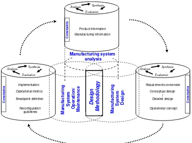
The framework proposed for the reconfiguration of manufacturing systems is based on the System Life-Cycle and the Unified Framework of Manufacturing Systems Design [Wu 2001].
Evaluation Analysis Synthesis Implementation Operational metrics Breakpoint definition Reconfiguration guidelines Co nst rai nt s | Evaluation Analysis Synthesis Requirements conversion Conceptual design Detailed design Operational concept Co nst rai nt s Manufacturing system analysis M a nufact uri n g S y stem D esi gn M a nu fa ct uri n g Sy s te m Op e ra ti on/ Ma in ten a n c e Design M e th o dolo g y Evaluation Analysis Synthesis Product information Manufacturing Information Con s tra ints
Figure 3-1 Framework for the reconfiguration of manufacturing systems (adapted
from [Wu 2001]).
3.1.1 Manufacturing System Analysis
Chapter 3. Methodology to Design Reconfigurable Manufacturing Systems
of manufacturing systems. Once the product and manufacturing information is gathered, it is important to structure it into the product and manufacturing models. Then, a reconfigurability assessment is performed in order to identify the requirements of reconfiguration according to the objectives and strategies of the manufacturing system.
3.1.2 Manufacturing System Design
3.1.3 Manufacturing System Operation and Maintenance
The third block of the framework is Manufacturing System Operation and Maintenance. In this block the implementation requirements of the manufacturing systems are required and a plan for the implementation is formulated to launch the manufacturing system. Once the manufacturing system is operating, it is necessary to establish operational metrics aligned with the design objectives to accomplish a manufacturing system performance. Some technological tools should be implemented to support the supervision of the manufacturing system and to follow the trends of the main indicators. It is important to establish a systematic supervision in order to identify breakpoints in the behavior of the manufacturing system that require a second cycle of reconfiguration of the manufacturing system. These breakpoints could be generated by changes in demand, introduction of new products, engineering changes in product, among others.
The integration of these three blocks is given by the Reconfigurable Manufacturing Systems Design Methodology which concentrate the concepts of the framework proposed and decomposed each stage in activities to analyze, evaluate and synthesize the inputs and outputs of each stage in order to design/reconfigure a manufacturing system.
3.2 Reconfigurable manufacturing systems design methodology
Chapter 3. Methodology to Design Reconfigurable Manufacturing Systems
a manufacturing system according to the requirements. The present research focuses on the Manufacturing System Development.
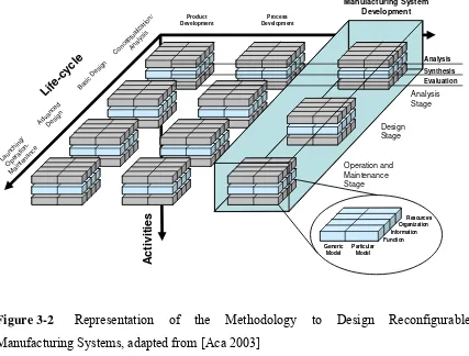
According to the framework presented in figure 3-1, each block correspond to one stage of the methodology presented the figure below. The Analysis Stage of the methodology corresponds to the Manufacturing System Analysis block of the framework; the Design Stage of the methodology corresponds to Manufacturing System Design block of the framework; and finally, the Operation and Maintenance Stage corresponds to the Manufacturing System Operation/Maintenance block of the framework.
Synthesis Analysis Evaluation Life -cyc le C once ptua lizat ion/ Anal ysis Basi c D
[image:20.612.94.521.306.630.2]esig n Adva nced Des ign Laun chin g/ Ope ratio n-Mai nten ance Ac ti vi ti e s Organization Function Resources Information Generic Model Particular Model Organization Function Resources Information Generic Model Particular Model Product Development Manufacturing System Development Process Development Analysis Stage Design Stage Operation and Maintenance Stage
Figure 3-2 Representation of the Methodology to Design Reconfigurable
Manufacturing Systems, adapted from [Aca 2003]
• Functions: represent the activities to implement the methodology (i.e. events, activities, processes).
• Information: represents enterprise’s objects and the information elements. It has to
be structured and shared between all the design processes.
• Resources: represents capabilities, tools, and resources.
• Organization: represents organizational levels, authorities and responsibilities. It
refers how people involved in design process are organized to achieve the manufacturing system design.
Any manufacturing system requires an arrangement of processes and activities in order to implement the methodology. When the methodology is implemented in a company it is important to define that the methodology can be adjusted according to its necessities. And some times several activities can be omitted. By the selection of specific tasks, a particular model of the methodology is created.
To support the implementation and an adequate documentation of the project, the methodology proposes a set of documents divided into two levels:
Instructive: they describe the activity to be performed, its objective, the input/output
information and the tool/technique that should be used during the execution of the activity.
Format: is a document used to record the information and data as a result of the execution of the activity performed. The formats used in the methodology are indicated in each instructive.
Chapter 3. Methodology to Design Reconfigurable Manufacturing Systems
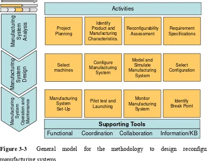
The general model of the methodology is presented in figure 3-3. The methodology is divided into three stages: i) Manufacturing system analysis stage, ii) Manufacturing system design stage, and iii) Manufacturing system operation and maintenance stage. Within each stage several activities are performed to implement the methodology and as a result, several activities has its own tollgate. In Manufacturing System Analysis stage four activities are performed: Project planning, identification of product and manufacturing characteristics, application of reconfigurability assessment and establishment of requirement specifications. Manufacturing System Design requires the execution of four activities: Selection of machines, configuration of manufacturing system, modeling and simulation of manufacturing system and selection of configuration. During Manufacturing System Operation and Maintenance stage a set of four activities is performed: manufacturing system set-up, pilot test and launching, monitoring of manufacturing system and identification of breakpoints for reconfiguration of the system.
Activities Ma nufac tu ring Sy st e m Analy s is Manufact u ring Sy st e m Design Manu fa c tu rin g Sy s tem Ope ra ti o n an d M a in te na nc e Project Planning Identify Product and Manufacturing Characteristics. Reconfigurability Assessment Requirement Specifications Select machines Configure Manufacturing System Model and Simulate Manufacturing System Select Configuration Manufacturing System Set-Up
Pilot test and Launching Monitor Manufacturing System Identify Break Point Supporting Tools
Functional Coordination Collaboration Information/KB
ENGINEERING
[image:22.612.90.499.363.682.2]MANUFACTURING SYSTEM DEVELOPMENT
Figure 3-3 General model for the methodology to design reconfigurable
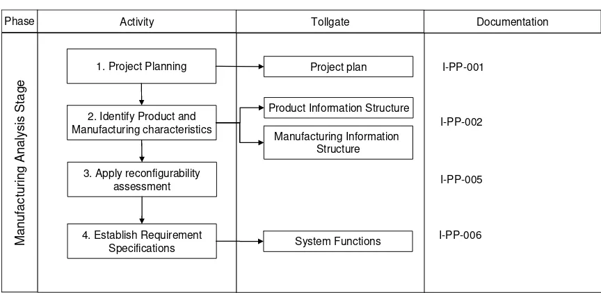
3.2.1 Manufacturing System Analysis Stage
The analysis stage of the methodology has the objective to plan the project, identify the main requirements of the manufacturing system that is under design and also to identify what attributes of reconfigurability should be included in the system. The activities to be performed are depicted in table 3-1. In this table three activities, tollgates and related proposed documentation is presented. The activities represent the functions to be done in order to implement the methodology. The tollgates represent the output of the activity. The documentation represents the documents proposed to support the implementation of the methodology.
.
2. Identify Product and Manufacturing characteristics
3. Apply reconfigurability assessment
Product Information Structure
M
a
n
u
fa
ct
u
rin
g A
n
al
y
s
is S
ta
g
e
Phase Activity Tollgate Documentation
Manufacturing Information Structure
4. Establish Requirement
Specifications System Functions
I-PP-002
I-PP-005
[image:23.612.89.521.289.500.2]I-PP-006 1. Project Planning Project plan I-PP-001
Table 3-1 Activities to perform in Manufacturing Analysis Stage
3.2.1.1 Project planning
Chapter 3. Methodology to Design Reconfigurable Manufacturing Systems
Company requirements: identify company requirements. The requirements define the scope, objectives and constrains of the project. It is important to identify which is the main goal of the project.
Company capabilities: The identification of company capabilities consists in the creation of a structure that represents what processes and products the company has. This task is oriented to understand what the manufacturing context within the company is, what is its main manufacturing strategy and general capabilities.
Once the requirements and capabilities have been identified, a plan program is created to guide the execution of the project. At this point it is necessary to identify clearly the different tollgates in each stage of the methodology and a tentative schedule indicating the list of activities to be executed, people, tools, and technologies that will support the implementation of the methodology are established.
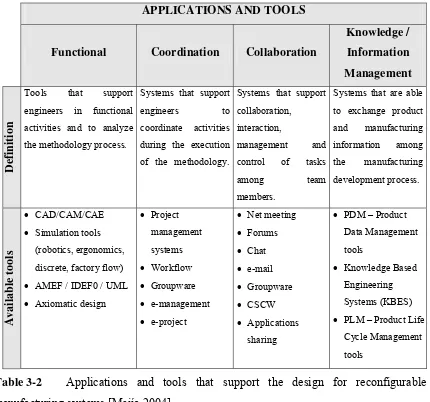
In the next table, the computer technology available to support the methodology is classified according to the taxonomy proposed by [Mejía 2004]: Functional, methodological, coordination, collaboration and information/knowledge technology tools (see table 3-2).
The applications and tools support the implementation of the methodology. The selection of these tools is aligned with the product and process characteristics.
3.2.1.2 Identify product and manufacturing characteristics
This characterization is important because it is necessary to locate the product and process into a group technology for a better design of the manufacturing system. This problem can solved by the methods proposed by [Askin and Standridge 1993].
APPLICATIONS AND TOOLS
Functional Coordination Collaboration
Knowledge / Information Management
Definition
Tools that support
engineers in functional
activities and to analyze
the methodology process.
Systems that support
engineers to
coordinate activities
during the execution
of the methodology.
Systems that support
collaboration,
interaction,
management and
control of tasks
among team
members.
Systems that are able
to exchange product
and manufacturing information among the manufacturing development process. Available tools • CAD/CAM/CAE • Simulation tools
(robotics, ergonomics,
discrete, factory flow) • AMEF / IDEF0 / UML • Axiomatic design
• Project management systems • Workflow • Groupware • e-management • e-project
• Net meeting • Forums • Chat • e-mail • Groupware • CSCW • Applications sharing
• PDM – Product
Data Management
tools
• Knowledge Based
Engineering
Systems (KBES) • PLM – Product Life
Cycle Management
[image:25.612.96.526.152.554.2]tools
Table 3-2 Applications and tools that support the design for reconfigurable
manufacturing systems [Mejía 2004].
3.2.1.3 Apply reconfigurability assessment
Chapter 3. Methodology to Design Reconfigurable Manufacturing Systems
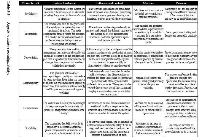
The reconfigurability assessment comprehends the five key characteristics that a RMS should. The assessment is applied in order to identify the requirements in terms of reconfigurability. This assessment will guide the designer to conceptualize the general reconfigurability the system should have in terms of the requirements. If the system already exists, the assessment will guide the designer to identify the opportunity areas in reconfigurability and the requirements. If the system is of new creation, the assessment will establish the reconfigurability requirements for the system.
The reconfigurability levels of a manufacturing system are depicted in table 3-3. It is considered modularity, integrability, convertibility, diagnosability, customization and scalability criteria for the assessment.
3.2.1.4 Establish requirement specifications
C h a p te r 3. Met ho d o lo gy t o D esi gn Reco nf ig ura b le M a nuf a ct u ri n g Syst em s R obe rt o R o sas R angel 45
Aspects to achieve recon
figurability.
Modularity
All major components of the system are modular. The structure of its elements including the product to be manufacture
is modular.
The software is modular and can handle tasks at various levels (control, monitoring,
communications, process planning,user interface, process controll, data collection)
Machines and tools that are included in system have a
modular structure.
The process has the capacity to manage the different modules
of the system; it has the capacity to be easily fined tune.
Integrability
The modules are able to integrate each other easily on the system by a set of
mechanical interfaces. The main components of the process are different,
it is needed to find out other tools in order to integrate both process arc
welding and arc brazing.
The software can be integrated easily to monitor and control the different modules of
the system by a set of informational interfaces. Software operates in
open-architecture principle.
The machine can integrate new modules to perform new
operations by its modular structure. It is capable to integrate new submodules or
tools.
New operations, tooling and fixtures are integrable precisely.
Convertibility
The system structure and its arrangement can response physically and
logically to changes in the product and part mix; its production functionality can
change from one product to another within the same family.
Software supports the reconfiguration of the system according to the production of parts and part mix. Software is able to be adapted
to the new configuration of the system structure and to execute fully its functionality without lossing the control.
Machine can be convertible in operations. It can execute different process by minimal changes in tools, fixtures.
Process can integrate new tools to increase its reliability. By the integration of new tools the process can be reconfigured.
Diagnosability
The system is able to detect unacceptable part quality and can reduce
its ramp-up time. Identifying the source of quality the system is able to rapidly be tuned fine. The system is able to identify itself its process status (working-not
working)
Software and control modules have the ability to support the diagnosability by tracking the error source and to control the
operation mode of the system under different circumstances. The system is able
to read the current state of the system and display it in a standard interface to take
correct actions.
Machine can execute the process reliably and precisely
in terms the process variables.
The process can be rapidly fine tuned to execute new operations. It also has clearly
control variables to achieve quality in process. Process can
be monitored in real time.
Customization
The system has the ability to be arranged in response to perform a variety of processes and products within its own
family.
Software and control can be customized easily and rapidly in response to the structure of the system and to achieve the
functions needed to control the system.
Machine can be customized adding new functionality or modules to execute more
operations.
Process can be customized to execute more operations or
processes without major changes in its structure. Only
adding new tools modules a new process can be configured.
Scalability
The system has the ability to scale its capability to accurately adjust the production capacity, or volume, of a
system in a short period of time.
The software and control can be scalable in order to increase its functionality; it can be integrated new modules to perform new
control operations and the integration
Machine can increase its capacity to perform more volume or can be scalable to
higher automation level.
[image:27.792.52.733.87.548.2]Chapter 3. Methodology to Design Reconfigurable Manufacturing Systems
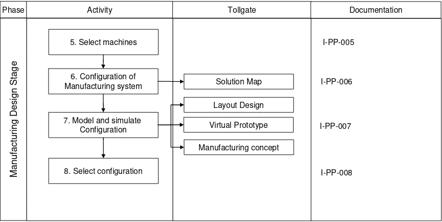
3.2.2 Manufacturing System Design Stage
The design stage of the methodology has the main objective to incorporate as an input the requirements and specifications identified in the previous stage into the design activities of the manufacturing system. The activities to be performed in this stage are depicted in table 3-4. In this table three activities, tollgates and related proposed documentation is presented. The activities represent the functions to be done in order to implement the methodology. The tollgates represent the output of the activity. The documentation represents the documents proposed to support the implementation of the methodology.
5. Select machines
6. Configuration of Manufacturing system
M
a
n
u
fa
c
tu
rin
g D
e
si
gn
S
ta
g
e
Phase Activity Tollgate Documentation
7. Model and simulate Configuration
Solution Map
Layout Design
Virtual Prototype
Manufacturing concept
I-PP-007
I-PP-008 8. Select configuration
[image:28.612.90.522.293.510.2]I-PP-006 I-PP-005
Table 3-4 Activities to perform during Manufacturing System Design stage.
3.2.2.1 Select machines
- Reconfigurability horizon
- Level of automation required
- Product to manufacture
- Manufacturing Process limitations
- Arrangement of the system
The methodology assumes that the process plan has been determined during product design process. Then, the process plan is an input for the methodology.
3.2.2.2 Configuration of manufacturing system
After machines and tools have been determined, the next step is to arrange machines into a system. Several concepts according to the selection of machines are generated in order to evaluate what configuration of the system is the best option according to the design objectives. Factors such as the production strategies and types of arrangement to manufacture should be considered. Criteria such as the capacity, control level and organization of resources are considered in order to generate feasible concepts for the configuration of the system.
3.2.2.3 Model and simulate concept
Chapter 3. Methodology to Design Reconfigurable Manufacturing Systems
two different perspectives: engineering and operational. The engineering perspective validate the structure of the elements and how they execute the process and function within the manufacturing system, The operational perspective helps to test and validate different operational circumstances, such as variations in the performance of each element, possible source of errors, variable trend performance, among others.
3.2.2.3.1 Manufacturing concept
Once the system has been simulated and validated it is important to support its operation and launching with detailed information such as the manufacturing concept. The manufacturing concept, see figure 3-4, has three main views: Product, Process and Resource. The product view provides the information about the product to manufacture (components, assemblies, material); the process view describes operations to execute in the process; the resource view contain the information related to equipment, tools and other resources required to execute the process.
Manufact uring Process Plann
Product View Process View Resource View
Product Operat ions Equipment Resources
- Has
* * - Has - Has
*
- Describe
* * - Describe * - Describe - Describe
* - Do
* - Produce
*
Figure 3-4 Manufacturing concept
reconfigurability before any physical change. Process plan guides the ramp-up and monitoring of the manufacturing system; it provides information on how the product is manufactured, the operations to perform, its sequence and what resources are needed to achieve a capacity level. The manufacturing concept includes the drawings and virtual models elaborated during the design process to support the set up of the manufacturing system and to speed up the installation and ramp up. In this case study, the manufacturing concept is not implemented.
3.2.2.3.2 Manufacturing concept
Once the system has been simulated and validated it is important to support its operation and launching with detailed information such as the manufacturing concept. The manufacturing concept, see figure 3-5, has three main views: Product, Process and Resource. The product view provides the information about the product to manufacture (components, assemblies, material); the process view describes operations to execute in the process; the resource view contain the information related to equipment, tools and other resources required to execute the process.
Manufact uring Process Plann
Product View Process View Resource View
Product Operat ions Equipment Resources
- Has
* * - Has - Has
*
- Describe
* * - Describe * - Describe - Describe
* - Do
* - Produce
*
Figure 3-5 Manufacturing concept
Chapter 3. Methodology to Design Reconfigurable Manufacturing Systems
manufacturing process plan allow to engineers to configure and reconfigure the manufacturing system virtually and to achieve, the main characteristics of reconfigurability before any physical change. Process plan guides the ramp-up and monitoring of the manufacturing system; it provides information on how the product is manufactured, the operations to perform, its sequence and what resources are needed to achieve a capacity level. The manufacturing concept includes the drawings and virtual models elaborated during the design process to support the set up of the manufacturing system and to speed up the installation and ramp up. In this case study, the manufacturing concept is not implemented.
3.2.2.4 Select configuration
An analysis of the different generated concept is necessary to determine what the best concept that achieves the design goals is. In this case a set of indicators to measure the level the system performance is proposed in appendix A. The indicators are selected according to the requirements established in first stage of the methodology and the facility level that is being designed. Other indicators can be added according to the objectives and requirements established in first stage of the methodology. Other factors such as the economic life cycle analysis of the system are not considered in this methodology.
3.2.3 Manufacturing Operation and Maintenance Stage
3.2.3.1 Manufacturing System Set-Up
The manufacturing system set up is the activity that integrates all the physical and logical elements designed for the manufacturing system. This activity installs de system and connects all the elements to achieve its main goal that is to produce a part. This activity is speed-up if a virtual design or prototype has been elaborated and the necessary elements for the set up of the system have been designed off-line, this means, in a virtual environment.
9. Manufacturing system Set-up
10. Pilot test and launching
11. Monitor manufacturing system Ma n u fa ct u ring O p e rat io n a n d M a in te na nc e S ta g e
Phase Activity Tollgate Documentation
12. Identify Break point Performance trends Reconfiguration driver I-PP-010 I-PP-011 I-PP-012 I-PP-009
Table 3-5 Activities to perform in Manufacturing Operations and Maintenance Stage
3.2.3.2 Pilot test and launching
The pilot test activity is the first production run of the manufacturing system in order to test how the system operates. The adjustment of parameters it is very important and risk management is required to avoid important failures during the launching period. Once the pilot test has been run and the parameters of the manufacturing system and process has been adjusted and validated, the system is able to start producing the part it was designed for.
Chapter 3. Methodology to Design Reconfigurable Manufacturing Systems
The follow up of the system is important in order to identify any deviation from the original design objectives. This means that the manufacturing system is monitored through the performance records generated among the operation stage. The information that the system should generate is related to the operational variables, process variables, productivity variables. The trend of these variables will determine any break point or requirement for adjustment of the system or even the reconfiguration of the system. It is helpful to follow up the behavior of the indicators proposed in the previous task. The methodology does not limit to use other indicators.
3.2.3.4 Identify break-points
The performance trends analysis will help to the manufacturing system manager to identify any negative trend of the performance of the variables defined to measure the behavior of the manufacturing system. The analysis can conclude in any of the five drivers for reconfigurability. If it is the case, a new cycle of the methodology should be started.
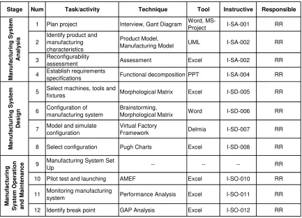
A general model for the implementation of the methodology is presented in table 3-7, where the activities are listed, what documentation is employed to record the information involved during the design process and what are the resources needed to implement the methodology.
Stage Num Task/activity Technique Tool Instructive Responsible
1 Plan project Interview, Gant Diagram Word,
MS-Project I-SA-001 RR
2
Identify product and manufacturing characteristics
Product Model,
Manufacturing Model UML I-SA-002 RR
3 Reconfigurability
assessment Assessment Excel I-SA-002 RR
4 Establish requirements
specifications Functional decomposition PPT I-SA-004 RR
5 Select machines, tools and
fixtures Morphological Matrix Excel I-SD-005 RR
6 Configuration of
manufacturing system
Brainstorming,
Morphological Matrix Word I-SD-006 RR
7 Model and simulate
configuration
Virtual Factory
Framework Delmia I-SD-007 RR
8 Select configuration Pugh Charts Excel I-SD-008 RR
9 Manufacturing System Set
Up -- -- -- RR
10 Pilot test and launching AMEF Excel I-SO-010 RR
11 Monitoring manufacturing
system Performance Analysis Excel I-SO-011 RR
12 Identify break point GAP Analysis Excel I-SO-012 RR
[image:35.612.90.523.70.382.2]M a nufa c tur ing S y s tem A n al ys is M a nufa c tu ri ng S y s tem De sign M a nufac tur ing S ystem O p e ra tion and M a intenanc e
Contents
List of Tables
Table 2-1 Comparison of manufacturing systems, adapted from [Koren et. al., 1999].20 Table 2-2 Characteristics that differentiate FMSs vs RMSs ... 21 Table 2-3 Scope of several research projects. ... 28 Table 2-4 Tools for design of manufacturing systems. ... 30 Table 3-1 Activities to perform in Manufacturing Analysis Stage ... 41 Table 3-2 Applications and tools that support the design for reconfigurable manufacturing systems [Mejía 2004]... 43 Table 3-3 Aspects to achieve reconfigurability... 45 Table 3-4 Activities to perform during Manufacturing System Design stage. ... 46 Table 3-5 Activities to perform in Manufacturing Operations and Maintenance Stage 51 Table 3-6 General model for the design methodology ... 53 Table 4-1 Drivers, strategies, and modes for reconfigurability, adapted from [Koren et al 1999]. 56
2 Literature review
2.1 Product Life Cycle
The global competition and the demand of low price products have forced companies to develop products and manufacturing systems in shorter times and with less cost. Due to this, it is important to consider the Product Life Cycle, which is shorter [Smith, 2000]. The Product Life Cycle describes the product’s evolution trough its life, from its creation to its disposal, including all the activities needed during the product development process. For example, [Alting, 1993] distinguishes six phases in a product’s life cycle: i) need recognition, ii) design development, iii) production, iv) distribution, v) use and vi) disposal (figure 2-1). However, most of other authors distinguish only four phases within the product life-cycle: i) design, ii) development, iii) production, iv) use and disposal [Asiedu and Gu, 1998].
LIFE – CYCLE DESIGN Design
Development Production
Distribution Need
Disposal/
Recycling Usage LIFE – CYCLE
DESIGN Design
Development Production
Distribution Need
Disposal/
[image:37.612.200.411.369.578.2]Recycling Usage
Figure 2-1 The life-cycle concept of product design [Alting, 1993].
Chapter 2. Literature Review
approach to address these issues in today’s competitive global market. Actually three different life cycles need to be considered during the product design: product life cycle, process and system life cycle and logistic support (figure 2-2).
Conceptual
Design PreliminaryDesign DetailedDesign Production Product Use Retirement /Disposal
Manufacturing System
Design ManufacturingOperations Recyclingprocess
Support and
Maintenance RecyclingSupport
Support System Design
Acquisition Phase UtilizationPhase RecyclingPhase
Product
Process
Logistic Support
Life Cycle
Figure 2-2 Parallel life cycles in product development [Asiedu and Gu, 1998].
The product life cycle is initiated when the needs are identified and extended through the design process, production, customer use, support and disposal. Process life cycle starts with the definition of the preliminary product design. Through the process life cycle production planning, plant layout, equipment selection, process planning and other activities are performed. The third an last parallel life cycle, logistic support, is initiated also at the preliminary design phase. This life cycle deals with the development of support for the design and production stages, consumer support and product recycling.
2.2 Systems Engineering Life Cycle
Systems Engineering is a management technology and leads to the notion of physical systems design, management systems design and information systems design. This technology assist and support policy making, planning, decision making and resource allocation or action deployment. Systems Engineering do this through quantitative and qualitative formulation, analysis and interpretation of alternatives referred to user’s needs, values and requirements [Sage, 1992].
This life cycle begins with the conceptualization and identification of needs, going to the specification of system requirements and architecture to install, evaluate, operate and maintain a system. It must be possible for a system to be effectively and efficiently produced, in order to achieve a high measure of functionality and performance. Also, the system must be so flexible to be modified, maintained and retrofitted through all the phases of the system design and development lifecycle. We call this overall cycle the systems engineering life cycle [Sage, 1992].
Some authors suggest that systems engineering is one of the best tools to solve complex problems such as the systems manufacturing design [Mason-Jones et. al., 1998]. One of the causes for not designing high performance manufacturing systems is due to the lack of internal systems integration. Therefore, systems engineering is the concept that supports the methodology proposed to design reconfigurable manufacturing systems.
A manufacturing system can be considered as a system that converts input flows (i.e. materials, manpower, etc.) into output flows (i.e. finished goods) [Mason-Jones et. al., 1998]. Based on this, it is necessary to explore different process models used for multiphased life-cycle models.
Chapter 2. Literature Review
The Department of Defense Model was developed in the second half of the twentieth century when the United States was developing large-scale complex military systems such as warships, airplanes, tanks, and command and control systems. To manage the risks in the application of advanced technology the Department of Defense created the guidelines contained in the DoD 5000 series. This model consists of four phases: Concept and Technology Development, System Development and Demonstration, Production and Deployment and Operation and Support.
The International ISO/IEC 15288 Model is a systems engineering standard. This model is becoming institutionalized in U.S. industry to replace previous standards. The model has six stages: Concept, Development, Production, Utilization, Support, and Retirement.
The Professional Engineering Model was developed by the National Society of Professional Engineers (NSPE) for the development of commercial systems. The model is mainly directed to develop new products, usually technology driven. This model is partitioned into six stages: Conceptual, Technical Feasibility, Development, Product Preparation, Full-Scale Production and Product Support.
Ch ap ter 2 . Litera tu re Review R obe rt o R o sas R angel 10
Parallel life cycles in sy
stem develo pm ent, adap ted from [Kossiakof an d Component advanced development System integration System demonstration
Production Utilization Support
Technical feasibility Production preparation Full scale production Systems Engineering Stages Systems Engineering phases Needs analysis Concept exploration Concept definition Advanced development Engineering design Integration and evaluation Production Systems Engineering Life Cycle model Mission need determination Post development Three-Phase Systems
Engineering System Definition System Design and development
System Operation and Maintenance
DoD 5000 phases
ISO/IEC 15288 stages
NSPE Stages
Concept and technology development System development and
demonstration Operation and support Production and deployment Operation and support Concept Development Concept exploration Conceptual
Concept development Engineering development
Chapter 2. Literature Review
The Systems Engineering Life Cycle corresponds to significant transitions into systems engineering activities through the system’s life cycle. The model is divided into three main stages and each stage subdivided into eight phases. The names of the subdivision of each stage represent the primary activities that occur in each part of the implementation of the model. Next two lifecycle models will be presented. The first one is based on three phases and the second one is performed of twenty two phases.
One of the life-cycle model is based on three phase, and it is used when a simple system is designed. The three main phases are: i) system definition, ii) System design & development and the iii) system operation and maintenance (figure 2-4).
Figure 2-4 Three-Phase System Engineering Life-Cycle Model [Sage, 1992].
A second model has been developed based on the Three-Phase model shown above. This is used for large scale systems. This model explain deeper the activities performed in the simpler appearing Three-Phase model. The activities are:
System
Definition
System Design
& Development
System definition
1. Perception of need 2. Requirements definition 3. Draft request for proposal 4. Comments on the RFP
5. Final RFP and statement of work 6. Proposal development
7. Source selection
System design and development
8. Development of refined conceptual architecture 9. Partitioning of the system into subsystems
10.Subsystem level specifications and test requirements 11.Development of components
12.Integration of subsystems 13.Integration of the overall system
14.Development of user training and aiding supports System operation and maintenance
15.Operational implementation or fielding of the system 16.Final acceptance testing
17.Operational test and evaluation 18.Final system acceptance
19.Identification of system change requirements
20.Bid on system changes or prenegotiated maintenance support 21.System maintenance change development
22.Maintenance testing by support contractor
Chapter 2. Literature Review
2.3 Agile Manufacturing
Agile manufacturing has become a manufacturing paradigm in the last years. However, it is difficult to find a common agreed definition for it. For example, [Gunasekaran and Yusuf, 2002] presented several definition such as the ability to thrive in a competitive environment of continuous and unanticipated change and respond quickly to changing markets; another given definition is the responsibility-based manufacturing; [Jain, 1995] stated that Agile Manufacturing focuses on rapidly setting up the whole organization for producing different products. Agile manufacturing makes emphasis on doing all tasks rapidly using various parts of the organization, all of whom are flexible and responsive. Then, Agile manufacturing takes the concept of flexible manufacturing to a higher plane, extending the concept to the whole organization, thus a key characteristics of an agile organization is flexibility [Aitken et. al., 2002]. Some of the common characteristics of Agile Manufacturing are [Jain, 1995]:
• Flexible production technologies • A knowledgeable, involved work force • Open management practices
• Rapid product and process development • Partnerships with suppliers and competitors
manufacturing identified the “increasingly” intensive computer modeling of processes with a view to eliminating pilot plants [Jain, 1995].
Agile manufacturing systems are born as a solution to manufacturing environment with an unpredictable and dynamic demand, and with a high degree of mass customization in its products [Sánchez and Gani, 2001]. The key enablers of agile manufacturing include [Gunasekaran and Yusuf, 2002]:
• Virtual enterprise formation tools/metrics
• Physically distributed manufacturing architecture and teams • Rapid partnership formation tools/metrics
• Concurrent engineering
• Integrated product /production business information system • Rapid prototyping
• Electronic commerce
Agile manufacturing is an extended concept of flexible technologies and the alignment of all the resources within the organization to response in an unpredictable manufacturing environment. Agile manufacturing requires new technologies that support the life cycle product in order to fulfill the customer requirements, such as reconfigurable manufacturing systems technologies [Gunasekaran and Yusuf, 2002]..
2.4 Flexible Manufacturing systems
Chapter 2. Literature Review
set of identical and/or complementary numerically controlled machines which are connected through an automated transportation system. Another definition is given by [Kaighobadi and Venkatesh, 1994] where define a FMS as a system dealing with high level distributed data processing and automated material flow using computer-controlled machines, assembly cells, industrial robots, inspection machines, together with computer integrated material-handling and storage systems. An FMS is capable of processing work-pieces of a certain mix in an arbitrary sequence with negligible setup delays between operations. In a FMS a set of preadjusted tools is available through a centralized tool magazine with direct access. FMSs can be configured to be process- or product-oriented. The main advantages of a FMS rely on being able to adapt well to most changes in the production.
Numerous goals are pursued by FMSs, typically the personnel costs reduction, increase of machine utilization, process time reduction for orders and lower inventory and capital costs. The FMSs aims the combination of advantages of a conventional quick change of production tasks with high capacity and low cost unit [Tempelmeier and Kuhn, 1993]. Some other factors to adopt FMS in manufacturing are the increased competition, market response improvements and flexibility in production [Narain and Yadav, 2004].
The major problems faced implementing FMS are [Kaighobadi and Venkatesh, 1994]: • Partially obsolete facilities
• Incompatibility between systems • Facilities with mixed processing • Dynamic volume and mix • Varieties of process options
dynamic operational factors into system design [Irani, 1999]. Then, a FMS can produce a variety of products, with changeable volume and mix, on the same predetermined capacity. FMS consists of expensive, general-purpose computer numerical controlled machines. FMSs are constructed with all possible functionality built in and it should be able to produce any part (within the machine envelope), at any mix of parts and in any sequence. This approach increase the cost related to investment by the installation of all possible functionality, requiring general purpose machines, very large tool magazines and multiple set of tools, making FMS a very expensive solution [Koren et. al., 1999].
2.5 Dedicated Manufacturing Lines
Dedicated Transfer Lines (DMLs) consist of up to several hundred interconnected process tools/machines. Each tool/machine within the system is highly specialized and performs one or two tasks. Material flow from one process tool to another is automated; the sequence of the flow is fixed, predetermined and it cannot be altered without stopping the system [Cardinall, 1995]. [Rehg and Kraebber, 2001] reported that DMLs are based on inexpensive fixed automation and produce a high volume product. The structure of a DML is of a linear network of service stations or machines separated by buffer storages; they are generally used in high volume production [Dinçer and Deler, 2000]. These types of manufacturing lines are called transfer machines or transfer lines. According to the main characteristics of a DML are:
• A series of closely spaced production stations are linked by material-handling
devices to move the parts from one machine to the next.
• There is a sequential production process, with each station performing one of the
process steps.
• The number of stations in the system is dictated by the complexity of the production process implemented.
Chapter 2. Literature Review
2.6 Reconfigurable Manufacturing Systems
Manufacturing companies in the 21st century will face unpredictable changes such as the high frequency introduction of new products, shorter product lifecycle, changes in market demands and environmental regulations. To survive in this new environment, companies need to react rapidly and cost effectively. As a response to the needs of the new global market, the Reconfigurable Manufacturing Systems (RMS) has been created. The RMSs are a new class of manufacturing systems and they are a new cost-effective response to the market requirements. A RMS is designed for rapid adjustment in its structure, including software and hardware, in order to quickly adjust production capacity and functionality within a part family. The reconfiguration of a RMS relied on the system design combined with the simultaneous design of open-architecture reconfigurable controllers with reconfigurable modular machines. The key characteristics of a RMS, according to [Koren et. al., 1999] are:
Modularity: This is dictated by the design of components, software and hardware, to be modular (structural elements, axes, controls, software, and tooling).
Integrability: Machine and control modules are designed with interfaces for component integration. The integrated system performance is predicted based on a given performance of its components and the interfaces of both software and machine hardware modules. The components are design to ready integration, it means, new technology is allowed to be integrated in a future.
Convertibility: The optimal operating mode is configured in batches that should be completed during one day, with short conversion times between batches. Conversion requires changing tools, part-programs, and fixtures. The system must be capable for quick changeover and quick system adaptability for future products.
more essential to rapidly tune the newly reconfigured system so products can be produced with quality.
Customization: Is the capability and flexibility of the system to math the product family. This characteristic has two aspects, the one relies on customized flexibility and the second one in customized control. Customized flexibility means that machines are built around parts of the family to be manufactured and provide the needed flexibility for those parts. Customized control is achieved integrating control modules with the aid of open-architecture technology, providing exact control functions needed.
Scalability: the ability to easily change existing production capacity by rearranging an existing production system and/or changing the production capacity of reconfigurable components within that system.
To achieve the goals of an RMS, there are several enabling technologies that are being developed. Some of these technologies concerned with the development of tools and methodologies to design the system and the evaluation of different configurations. Other technologies that enable the reconfigurability in manufacturing systems is the modular structure and the open architecture in control in order to be upgraded and customized the control besides the integration of new software/modules according to the reconfigurability of the manufacturing system. The development of approaches for design and construction of reconfigurable machine/tools is another technology that is being developed [Mehrabi et. al., 2000].
2.7 Manufacturing Systems, from Flexibility to Reconfigurability
Chapter 2. Literature Review
companies needs to react in a rapidly and cost-effective manner to cope with this challenges.
Current practice in product design through its life cycle requires of a huge amount of time [Young, 2003]. In last years the time consumed by product design process has been reduced by Computer Aided Design (CAD) technologies; this has not happened in manufacturing system design process [Koren et. al., 1999]. In order to reduce the time spent in manufacturing system development, and production, several changes in the manufacturing system are needed. These changes can be achieved incorporating some level of reconfigurability through the integration of new technologies. The contrast of the current practice and the required one is depicted in figure 2-5.
Product development
Manufacturing Systems Design and Build Ramp Up Production
Leadtime Product in Market
Product A development
Manufacturing Systems
Design and Build Ramp Up Produce A
Leadtime
Product B development
Product C development
RU Produce A + B RU Produce A+B+C
Physical Reconfiguration
Current Practice
Future Practice
Visualization
Reconfiguration System Configuration 1
System Configuration 2
System Configuration 3
Figure 2-5 Trends in manufacturing system development, adapted from [Koren et. al.,
1999].
variety of products in a changeable volume and mix on the same system. A FMS consists usually of expensive, general-purpose Computer Numerically Controlled (CNC) machines and other programmable automation such as an Automated Guided Vehicle (AGV). The FMS’s throughput is lower than that of DML. A FMS is designed for a variety of cycle times, then, the challenge of fluctuation in product demand can be dealt with a FMS; this is because a FMS is scalable. In contrast, the cost of a FMS is high, due to the machine focus and single-tool design. Agile manufacturing integrates flexible technologies and align all the resources within organization to support the life cycle product and to fulfill customer requirements. By the integration of concurrent tools, new technologies and new manufacturing systems, manufacturing companies can respond to changing market conditions.
In order to have better understanding related to FMS, DML and RMS a summary of its characteristics is depicted in Table 2-1.
DML FMS RMS
Cost Low Expensive Scalable
System Focus Part Machine Part family
Capacity Fixed Flexible Customized
Control Dedicated,
fixed Modular
Modular, open architecture
Machine structure Fixed Fixed Adjustable
Scalability No Yes Yes
Flexibility No General Customized
Simultaneous
operations Yes No Yes
Table 2-1 Comparison of manufacturing systems, adapted from [Koren et. al., 1999].
Chapter 2. Literature Review
part. The main characteristics of the RMS make it scalable in hardware and software, and it is possible to add “building blocks” to it in order to increase its capacity on demand.
Table 2-2 shows the characteristics that differentiate the FMS vs. a RMS.
FMS Characteristics RMS Characteristics
Produce several types of parts Oriented to produce a family of products Fixed and predetermined hardware and
software.
Capable to incorporate basic process modules. Reconfiguration allows adding, removing or modifying specific capabilities, controls or system structure.
Predetermined and fixed layout Layout can be rearranged quickly and
reliably Built with all possible flexibility and
functionality available, with an excess of tooling capacity and varieties of processes options.
Exact functionality and capacity needed when it is needed; functionality and capacity can be upgraded adding minimal modules.
Table 2-2 Characteristics that differentiate FMSs vs RMSs
RMS
Time 1 FMS 1
Product A
RMS
Time 2
Product A + B Product B + C Multiple Products
RMS
Time 3
Functionality
Capacit
y
FMS 2
Figure 2-6 Dimensions to differentiate FMS-RMS [Koren et. al., 1999]
[Mehrabi et. al., 2000] identified the necessity to investigate in the system-level design. Some of the key research issues are:
• Development of a systematic approach for design of RMS
• Analysis of the impact of system configuration on reliability, quality and cost • Extensive use of CAD tools in order to ram-up manufacturing systems
• Analysis and design of full process from recognizing customer needs through operation selection and system specification
2.8 New trends in manufacturing system design
![Figure 2-1 The life-cycle concept of product design [Alting, 1993].](https://thumb-us.123doks.com/thumbv2/123dok_es/4423812.34349/37.612.200.411.369.578/figure-life-cycle-concept-product-design-alting.webp)
![Figure 2-7 Manufacturing system life cycle, adapted from [Asiedu and Gu, 1998].](https://thumb-us.123doks.com/thumbv2/123dok_es/4423812.34349/57.612.94.441.74.321/figure-manufacturing-life-cycle-adapted-asiedu-gu.webp)
