INSTITUTO TECNOLÓGICO Y DE ESTUDIOS SUPERIORES DE MONTERREY
PRESENTE.-Por medio de la presente hago constar que soy autor y titular de la obra denominada
, en los sucesivo LA OBRA, en virtud de lo cual autorizo a el Instituto Tecnológico y de Estudios Superiores de Monterrey (EL INSTITUTO) para que efectúe la divulgación, publicación, comunicación pública, distribución, distribución pública y reproducción, así como la digitalización de la misma, con fines académicos o propios al objeto de EL INSTITUTO, dentro del círculo de la comunidad del Tecnológico de Monterrey.
El Instituto se compromete a respetar en todo momento mi autoría y a otorgarme el crédito correspondiente en todas las actividades mencionadas anteriormente de la obra.
Modeling and Principles of Ionic Polymer-Metal Composite
Electroactive Polymers as Actuators for Position Reconfigurable
Devices-Edición Única
Title Modeling and Principles of Ionic Polymer-Metal Composite Electroactive Polymers as Actuators for Position Reconfigurable Devices-Edición Única
Authors Josué Florencio Guzmán Lozano
Affiliation ITESM-Campus Monterrey
Issue Date 2007-12-01
Item type Tesis
Rights Open Access
Downloaded 19-Jan-2017 10:07:54
DIVISIÓN DE INGENIERÍA Y ARQUITECTURA PROGRAMA DE GRADUADOS EN INGENIERÍA
TECNOLÓGICO
DE MONTERREY,
Modeling and Principles of Ionic Polymer-Metal Composite Electroactive Polymers as Actuators for Position Reconfigurable Devices
TESIS
PRESENTADA COMO REQUISITO PARCIAL PARA OBTENER EL GRADO ACADÉMICO DE:
MAESTRO EN CIENCIAS
ESPECIALIDAD EN SISTEMAS DE MANUFACTURA
POR:
JOSUÉ FLORENCIO GUZMÁN LOZANO
CAMPUS MONTERREY
DIVISIÓN DE INGENIERÍA Y ARQUITECTURA PROGRAMA DE GRADUADOS EN INGENIERÍA
Los miembros del comité de tesis recomendamos que el presente proyecto de tesis presentado por el Ing. Josué Florencio Guzmán Lozano sea aceptado como requisito parcial para obtener el grado académico de:
Maestro en Ciencias en Sistemas de Manufactura Especialidad en Materiales
Comité de Tesis:
______________________________ Dr. Jorge Armando Cortés Ramírez
Asesor
________________________________ _______________________________ Dr. Bernard Jean Marie Micheli Masson M.C. Jesús Ángel Valencia Gallegos
Sinodal Sinodal
Aprobado:
_______________________ Dr. Francisco Ángel Bello
God, my heavenly Father, for countless hours of encouragement, dedication, and concern to myself; and for never giving up on me. For a little bit of science might make us
atheists, a profound knowledge about things will actually lead us to God.
To my father, Florencio Guzman, who raised me since the day I was born, and has dedicated his entire life for the good of his family in Mexico, Peru, Colombia, and the United States of America. His legacy has reached four nations. And we all thank him that in one important day of his life he continued to live for something better and greater that could only be given by God’s hand.
To my mother, Maria E. de Guzman, to whom I give thanks for countless hours of listening to my words, for listening to my dreams, and for giving me the exact words that I needed at the moments of despair and doubt. Her advice through life has become one of the most priceless things I have ever had.
To my brother, Juan E. Guzman, with whom I have shared some of the triumphs and flaws in life, as we grew together, and now we see each others’ lives finding a purpose in the ways that have been traced by our decisions. For his dedication to the work, his energy, and his persistence to remain in the path of his calling.
I would like to thank Dr. Jorge A. Cortes R. for these two years of being my advisor and leader of our research group. His concern and dedication to each of our projects has given me the opportunity to study the Masters’ Degree Program by working with him. His constant advice has made possible the completion of this work, and fulfillment of many goals that have been the result of his encouragement and guidance.
I want to thank Dr. Bernard J. M. Micheli M. and M.C. Jesús A. Valencia. G. for taking the time to revise and evaluate this work. I appreciate very much your opinions and comments on what is written and explained in this thesis in order to complete each and every aspect of it in the best way possible. I appreciate very much your advice and teaching during my undergraduate studies, where I found my interest in the study of polymer science and engineering.
I want to thank Dr. Takaomi Kobayashi (小林高臣) for his visit to our university and
the opportunity to work with him and his students at Nagaoka Institute of Technology. Thank
you to Yusuke Hoshina (保科勇輔), Zhang Quanqia, Minoru Yamamoto (山本稔) for their
help with the laboratory equipment and experimentation.
Thank you to all my Laboratory colleagues at Mexico: Ruth O. Valdés N., M. Ignaicio
Varela J., Luis G. Loo C., and Japan: Makoto Arisawa (有沢誠人), Che Ku Mohammad
Faizal, Kyaing Kyaing Latt, Yoshihiko Sato (佐藤慶彦), Ngo Le Ngoc, Takashi Onozuka (小
野塚卓), Kaori Katagawa (片川香織), Masaru Oushiro (大城優), Tsubasa Takano (高野翼),
The present work is in the field of functional materials known as electroactive
polymers. Electroactive polymers work as a system, enhancing the use of electrical
energy to produce displacements and possible mechanical work. An ionic polymer-metal
composite is one type of materials. The use of ionic polymer-metal composite actuators is
currently a field in development with several areas to be fulfilled by researchers.
The objective of this investigation is to develop a constitutive model of the
bending deformation of an electroactive ionic polymer-metal composite strip as a
response to an electrical input and the ion contents of the material.
The constitutive model uses an approach of phase transformation to describe the
changes in the cross section of an ionic polymer-metal composite, while modeling the
deformations as a bending beam system. For the solution of the constitutive model, the
composite material is prepared and characterized. The information about deformation in
terms of potential difference, frequency and ionic specie content is gathered through an
experimental analysis. The results of this analysis are used to find the parameters in the
proposed model. The constitutive model may be applied then to as an engineering tool to
propose the design and simulation for a reconfigurable system that uses the IPMC strip
Dedicated to… x
ACKOWNLEDGEMENTS xi
SUMMARY xii
CONTENTS xiii
LIST OF FIGURES xvi
LIST OF TABLES xviii
SYMBOLOGY xviii
1. BACKGROUND 1
1.1. INTRODUCTION 1
1.2. JUSTIFICATION 4
1.3. HYPOTHESIS 5
1.4. OBJECTIVE 6
1.4.1. General Objective 6
1.4.2. Specific Objectives 6
1.5. METHODOLOGY 6
1.5.1. Formulation of the constitutive model for the bending deformation phenomenon present in an ionic polymer-metal composite strip based on the applied voltage, frequency, and ionic content.
7 1.5.2. Preparation of a three-layer ionic polymer-metal composite material by metal deposition with
oxidation and reduction reactions. 7
1.5.3. Experimental analysis of the prepared material based on the voltage, frequency, ionic content, to
measure the displacement. 8
1.5.4. Solution for the parameters based on experimental results for application of the constitutive model
in the simulation and engineering of position reconfigurable systems. 8
1.6. REFERENCES 9
2. FORMULATION OF THE CONSTITUTIVE MODEL FOR THE BENDING DEFORMATION
PHENOMENON PRESENT IN AN IONIC POLYMER-METAL COMPOSITE 10
2.1 INTRODUCTION 10
2.2. IDENTIFICATION OF THE MATERIALS 10 2.2.1. Description of electroactive polymers 11 2.2.2. History in the research of EAP 12 2.2.3. IPMC as the state-of-the-art in EAP 15 2.2.4. Identification of the materials that compose the IPMC 16 2.3. DISCUSSION OF MODELS OF IONIC POLYMER-METAL COMPOSITES DEFORMATION
FOUND IN LITERATURE
19
2.4. MODELING OF THE DEFORMATION PHENOMENON IN IONIC POLYMER-METAL COMPOSITES
2.5. CHAPTER REMARKS 31
2.6. REFERENCES 33
3. PREPARATION OF A THREE-LAYER IONIC POLYMER-METAL COMPOSITE MATERIAL BY
METAL DEPOSITION WITH OXIDATION AND REDUCTION REACTIONS 36
3.1 INTRODUCTION 36
3.2. PREPARATION PROCEDURE FOR IPMC 36
3.2.1. Surface roughening and cleaning of the membrane 37 3.2.2. Ion-exchange process for platinum adsorption 37 3.2.3. Reduction process for primary plating 38 3.2.4. Additional reduction for developing the metal layers 39 3.2.5. Metallic ion implantation 40 3.3. CHARACTERIZATION OF THE PREPARED IPMC 41 3.3.1. Characterization using SEM 41 3.3.1.1. IPMC using roughening 42 3.3.1.2. IPMC without using roughening 44 3.3.1.3. Discussion of the results using SEM 45 3.3.2. Characterization using AFM 46
3.4. CHAPTER REMARKS 48
3.5. REFERENCES 50
4. EXPERIMENTAL ANALYSIS OF THE PREPARED MATERIAL BASED ON THE VOLTAGE,
FREQUENCY AND IONIC CONTENT, TO MEASURE THE DISPLACEMENT 51
4.1. INTRODUCTION 51
4.2. EXPERIMENTAL PLANNING 51
4.2.1. Input variables 52
4.2.2. Output variable 53
4.2.3. Diagram of experimental planning 53 4.3. DESIGN AND ARRANGEMENT OF THE EXPERIMENTAL SETTING 55 4.4. RESULTS FROM THE EXPERIMENTAL DATA 57
4.4.1. Use of Lithium ion 58
4.4.2. Use of Potassium ion 60
4.4.3. Use of Sodium ion 62
4.4.4. Use of Magnesium ion 64
4.4.5. Use of Calcium ion 66
4.5. DISCUSSION OF THE OBTAINED RESULTS 68
4.6 CHAPTER REMARKS 69
5.1. INTRODUCTION
5.2. MATHEMATICAL FITTING OF THE DATA TO OBTAIN PARAMETERS 72 5.2.1. Parameters for the use of Lithium ion 73 5.2.2. Parameters for the use of Potassium ion 75 5.2.3. Parameters for the use of Sodium ion 77 5.2.4. Parameters for the use of Magnesium ion 79 5.2.5. Parameters for the use of Calcium ion 81
5.3. CONCLUSIONS OF THE CHAPTER 83
6. CONCLUSIONS 83
6.1. CONCLUDING REMARKS 84
input conditions. 2 Fig. 1.2 Diagram showing the elements that compose an IPMC. 2 Fig. 1.3 Diagram explaining the deformation presented at an IPMC. 3 Fig. 2.1 Some examples of the possible deformations achieved by a stimulated electroactive
polymeric material. 11
Fig. 2.2 Successive photographs of an IPMC strip that shows very large deformation in the presence
of low voltage. 15
Fig. 2.3 Structure of perfluorinated polymers a) Nafion® and b) Flemion®. 18 Fig. 2.4. A system having a beam being deformed by a load (virtual) P, producing a total
displacement δ. 20
Fig.2.5. Linear relationship between the virtual load P and the total displacement δ. 21 Fig. 2.6. Diagram showing the change in the phase at one side of the cross section if the membrane. 22 Fig. 2.7. Behavior of the volume fraction at both side of the cross section of the membrane. 23 Fig. 2.8. Behavior of the volume fraction Vfi at the expanding side of the cross section at a specific
frequency ν. 24
Fig. 2.9. Behavior of the volume fraction Vfi at the expanding side of the cross section at
several frequency conditions. 25
Fig. 2.10. The characteristic voltage VC is the value of potential difference at which the
system is at 50% of transformation. 26
Fig. 2.11. The possible behaviors of characteristic voltage VC vs. Frequency and the material
parameter B vs. the ionic radius. 26
Fig. 2.12. The total displacement as a linear relationship between the factor K and the strain ε. 27 Fig. 2.13. Behavior of total displacement δ vs. strain ε at different conditions of potential difference. 28 Fig. 2.14. Linear relationship between the factor K and the volume fraction Vfi. 28 Fig. 3.1. Comparison of Nafion® ion-exchange membrane before (a) and after (b) the the platinum
plating process to produce the IPMC. 40
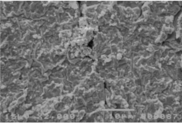
Fig. 3.2. Image of the surface of the IPMC as obtained by roughening the surface of the base polymer
and then doing the platinum deposition. 42
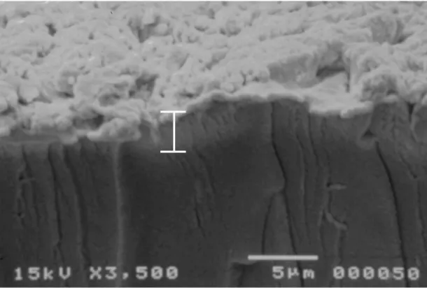
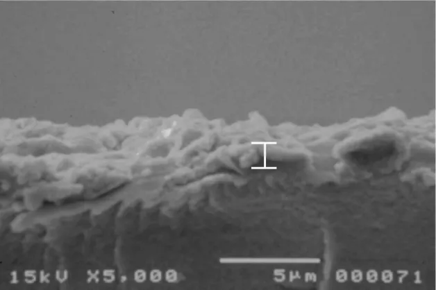
Fig. 3.3. Image of the cross section of the IPMC as obtained by roughening the surface of the base
polymer and then doing the platinum deposition. 43
Fig. 3.4. Image of the surface of the IPMC as obtained by doing the platinum deposition without
without roughening the surface of the base polymer. 45 Fig. 3.6. Image of AFM analysis for the morphology presented at the surface a Nafion ion-exchange
membrane. 47
Fig. 3.7. Image of AFM analysis for the morphology presented at the surface platinum
electrode of the IPMC. 47
Fig. 4.1. Diagram showing the proposed experimental setting for measuring the total displacement of
an IPMC strip. 55
Fig. 4.2. Photograph of the IPMC strips placed in a 3%wt solution of the chloride salt of the ionic
specie to use. 56
Fig. 4.3. Photograph of experimental setting for displacement measurement. 57 Fig. 4.4. Total displacement vs. the applied voltage at different frequency for Lithium system. 59 Fig. 4.5. Total displacement vs. the applied voltage at different frequency for Potassium system. 61 Fig. 4.6. Total displacement vs. the applied voltage at different frequency for Sodium system. 63 Fig. 4.7. Total displacement vs. the applied voltage at different frequency for Magnesium system. 65 Fig. 4.8. Total displacement vs. the applied voltage at different frequency for Calcium system. 67 Fig. 4.9. Electromechanical response of tetra-n- butylammonium in an IPMC using Flemion as a base
polymer. 68
Fig. 5.1. Total displacement vs. the applied voltage at different frequency in solved constitutive
model for Lithium system. 74
Fig. 5.2. Total displacement vs. the applied voltage at different frequency in solved constitutive
model for Potassium system. 76
Fig. 5.3. Total displacement vs. the applied voltage at different frequency in solved constitutive
model for Sodium system. 78
Fig. 5.4. Total displacement vs. the applied voltage at different frequency in solved constitutive
model for Magnesium system. 80
Fig. 5.5. Total displacement vs. the applied voltage at different frequency in solved constitutive
Table 4.2. Experimental data obtained for an IPMC with Lithium as its ion content. 58 Table 4.3. Experimental data obtained for an IPMC with Potassium as its ion content. 60 Table 4.4. Experimental data obtained for an IPMC with Sodium as its ion content. 62 Table 4.5. Experimental data obtained for an IPMC with Magnesium as its ion content. 64 Table 4.6. Experimental data obtained for an IPMC with Calcium as its ion content. 66 Table 5.1. Model displacements obtained for an IPMC with Lithium as its ion content. 73 Table 5.2. Model displacements obtained for an IPMC with Potassium as its ion content. 75 Table 5.3. Model displacements obtained for an IPMC with Sodium as its ion content. 77 Table 5.4. Model displacements obtained for an IPMC with Magnesium as its ion content. 79 Table 5.5. Model displacements obtained for an IPMC with Calcium as its ion content. 81
SYMBOLOGY
P Virtual load
δ Total displacement
X Distance of a beam
σ Bending stress
ε Strain or deformation
E Modulus of elasticity
Z Section Modulus
K Factor for the virtual, geometric, and material conditions
Vfi Volumetric fraction of the counter-ion present or missing in the material
ν Frequency
V Electrical potential difference
VC Characteristic potential difference at constant frequency conditions B Parameter for the constitution of the material
Table 4.1. Experimental planning of the bending actuation of an IPMC material strip. 54 Table 4.2. Experimental data obtained for an IPMC with Lithium as its ion content. 58 Table 4.3. Experimental data obtained for an IPMC with Potassium as its ion content. 60 Table 4.4. Experimental data obtained for an IPMC with Sodium as its ion content. 62 Table 4.5. Experimental data obtained for an IPMC with Magnesium as its ion content. 64 Table 4.6. Experimental data obtained for an IPMC with Calcium as its ion content. 66 Table 5.1. Model displacements obtained for an IPMC with Lithium as its ion content. 73 Table 5.2. Model displacements obtained for an IPMC with Potassium as its ion content. 75 Table 5.3. Model displacements obtained for an IPMC with Sodium as its ion content. 77 Table 5.4. Model displacements obtained for an IPMC with Magnesium as its ion content. 79 Table 5.5. Model displacements obtained for an IPMC with Calcium as its ion content. 81
SYMBOLOGY
P Virtual load
δ Total displacement
X Distance of a beam
σ Bending stress
ε Strain or deformation
E Modulus of elasticity
Z Section Modulus
K Factor for the virtual, geometric, and material conditions
Vfi Volumetric fraction of the counter-ion present or missing in the material
ν Frequency
V Electrical potential difference
VC Characteristic potential difference at constant frequency conditions B Parameter for the constitution of the material
1. BACKGROUND
1.1 INTRODUCTION
Polymer science has had a major impact on the way we live today; with new applications being researched. Currently, several efforts in the field of research and development have been focused in the future of functional materials. Functional materials are distinctly different from structural materials, and their physical and chemical properties are sensitive to a change in the environment such as temperature, pressure, electric field, magnetic field, optical wavelength, adsorbed gas molecules and the pH value. The functional materials utilize the native properties and functions of their own to achieve an intelligent action [1.1]. This means that the material by itself is able to work as a system; and polymers may be found among them. Very recently, polymeric materials have started to bloom into this new application due to the successful development of Electroactive Polymers (EAP).
The study of electroactive polymers (EAP) has followed the typical curve of laboratory curiosities that percolate in the back rooms of industrial labs for years and then seem to burst on the scene in the form of startups, annual conferences and industry associations dedicated to their development. Several conferences are now devoted to the subject, artificial muscle institutes are being established, and companies offering design services and products in the field are open for business [1.2].
Ionic polymer-metal composites (IPMC), a type of EAP, were discovered almost fifteen years ago as a result of the work done by researchers in the United States and Japan, separately [1.3-1.5]. These materials are generally produced as thin strips that present a bending deformation in response to an electrical stimulus. Fig. 1.1 shows an example of the deformation of an electrically stimulated IPMC.
Fig. 1.1. Example of an ionic-polymer metal composite deforming in response of electrical input conditions.
A typical ionic polymer-metal composite consists of a thin (0.2mm) base polymer membrane with metal electrode (5-10 m thick) plated on both faces. The polyelectrolyte matrix of the base polymer is neutralized with an amount of counter-ions, balancing the charge of the anionic (negative) functional groups found inside the polymer [1.6]. Fig. 1.2 shows the basic constitution of an IPMC as a three-layered arrangement along the cross section of the thin membrane.
Fig. 1.2. Diagram showing the elements that compose an IPMC. The image representing the cross section area of a thin flexible membrane shows the presence of a base polymer with two separate metallic electrodes in the upper and lower surfaces of the same.
An IPMC material is able to deform, exhibiting a bending action, when subject to an electric potential difference. The electroactive mechanism by which the material shows its bending action is as follows: When both layers at the top and bottom surfaces of the base
Base Polymer made of an ion-exchange membrane
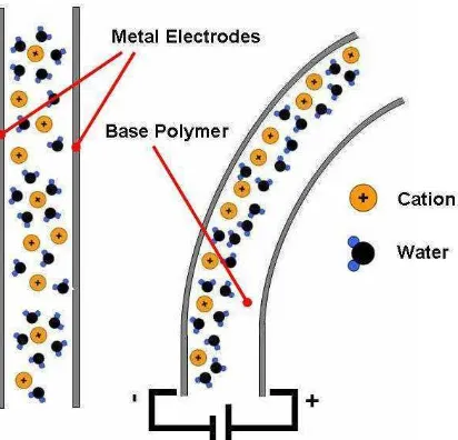
[image:16.612.201.461.387.552.2]polarization created at both electrodes will promote the migration of the embedded cations inside the membrane into the cathode side (with negative charge). Since the cations are surrounded by water molecules, those are also carried by the cations into the cathode side. The accumulation of both cations and water molecules causes an imbalance which makes the current side to expand by the sudden increase in the concentration of these cations and molecules, while it contracts in the other side due to the decrease in the concentration. All these changes make the strip to build a curvature towards the anode side of the circuit, which is stated here as a bending. This reaction happens in a fraction of a second; enabling to have several deformations achieved at real time. Fig. 1.3 shows a diagram which represents the IPMC before and after is electrically stimulated.
Fig. 1.3. Diagram explaining the deformation presented at an IPMC. When not connected, cations and water molecules are scattered along the polymer’s cross section. When an electric input is applied, this molecules travel to the cathode side causing a sudden increase in the volume. Along with the sudden decrease at the anode side, the polymer is able to bend.
[image:17.612.211.417.319.517.2]The up-to-date research and development in the IPMC as actuators or sensors has given some fundamentals, preparation techniques, and modeling of the phenomena regarding the deformation of the material from a scientific point of view [1.7-1.10]. However, a bridge between the scientific research and the technological application is necessary for the engineering of these functional materials.
1.2. JUSTIFICATION
The formulation of a constitutive model represents the bridge where the scientific fundamentals of the material are linked to the design and simulation of reconfigurable tools and devices. Previous investigations on the IPMC have worked in constitutive models of the deformation phenomenon, basing the equations in several characteristics present at the time when the material reconfigures itself in a bending action [1.11-1.14]. However, since IPMC are synthetic complex materials, a fundamental theory explaining the bending action of the material is far from being related to a system affected by any natural phenomena. Therefore, the bending behavior present in an IPMC is the result of the combination of several factors which go around the constitution of the material (base polymer, ion exchange, conducting material, ionic content) and the conditions for its actuation (electric potential difference, frequency, mechanical configuration); stressing into following a modeling approach based on the lineaments of an artificial material under the influence of artificially induced factors.
is possible. Analogically to this, the cross section of an IPMC may experiment something similar to a phase transformation when subject to an electric potential difference. This concept, based on the scientific method, could give the description of these artificial materials a new and more effective approach.
Since a constitutive model is a mathematical approximation which tries to describe the basics of the material behavior in a quantitative way, consequently, an experimental analysis is involved in order to place the IPMC in a set of conditions that trigger its characteristic response to determine the parameters which are strongly related to the observed phenomenon. The experimentation, at the same time, requires samples of the actual synthetic material to work at the conditions dictated in a design of experiments, to then carry out the processes that may give the results required to find the solutions for the modeling.
The parameters obtained by adjusting the values of input and response of the system into the model may be applied as an engineering tool for the design and construction of artificial systems; which are characterized by the actuation phenomenon represented in the proposed constitutive equation, for reconfiguring the position of a strip form made of the IPMC material.
1.3. HYPOTHESIS
1.4. OBJECTIVES
1.4.1 General Objective
The main objective of this investigation is to develop a constitutive model of the bending of a strip of IPMC in response to parameters such as: potential difference, frequency, and size of the aggregate counter-ion (ionic content) of the formed composite that may be used in numerical simulation and application for position reconfigurable systems.
1.4.2 Specific objectives
This objective is divided into the next specific objectives:
1) Formulation of constitutive model for bending deformation phenomenon present in an ionic polymer-metal composite strip based on the applied voltage, frequency, and ionic content.
2) Preparation of a three-layer ionic polymer-metal composite material by metal deposition with oxidation and reduction reactions.
3) Experimental analysis of the prepared material based on the voltage, frequency, ionic content, to measure the displacement.
4) Solution for the parameters based on experimental results for application of the constitutive model in the simulation and engineering of position reconfigurable systems.
1.5. METHODOLOGY
their respective objectives, activities, and results; followed by the conclusions of each chapter and the references used.
1.5.1. Formulation of constitutive model for bending deformation phenomenon present in an ionic polymer-metal composite.
This stage has the objective to propose a constitutive model of the bending phenomenon of an IPMC strip in terms of the applied potential difference, the frequency, and the distinctive characteristics of the implanted ionic specie within the material. In this part the fundaments of electroactive polymers (EAP) are explained in order to locate the IPMC as part of the current state-of-the-art in this field. A brief description found in literature of the factors considered in the modeling of this system is presented, as well as the proposed model is formulated based on the deformation of a beam and the phase transformation of a material in order to obtain the total displacement, the deformation, and the modulus of elasticity of the system. The further development of the constitutive model requires experimental procedures using actual samples of IPMC material.
1.5.2. Preparation of a three-layer ionic polymer-metal composite material.
1.5.3. Experimental analysis of the prepared material to measure the displacement.
In this part, the objective is to gather information about the bending of the prepared IPMC strip by doing an experimental planning where the strip is subject to input variables in order to measure a response, the data obtained from these tests are then arranged graphically, and the results are compared from one group of experiments to another. The experimental data is obtained for solution of the mathematical modeling of the bending phenomenon in the IPMC.
1.5.4. Solution for parameters based on experimental results for application of the constitutive model.
1.6 REFERENCES
[1.1] Wang, Z. L., Kang, Z. C., Functional and Smart Materials Structural Evolution and Structure Analysis, 1st edition, Plenum Publishing Corp., NY, 1998.
[1.2] Brown, Chappell, Getting a grip on artificial muscles, Electronic Engineering Times, Oct 4, 2004, issue 1341, pp. 1, 18-19.
[1.3] Oguro, K., Kawami, Y., Takenaka, H., Bending of an ion-conducting polymer film-electrode composite by an electrical stimulus at low voltage, Trans. Journal of Micromachine Society, Vol. 5, 1992, pp.27-30.
[1.4] Shahinpoor, M., Conceptual design, kinematics and dynamics of swimming robotic structures using ionic polymeric gel muscles, Smart Materials and Structures, Vol. 1, No.1, 1992, pp. 91-94.
[1.5] Sadeghipour, K., Salomon, R, Neogi, S., Development of a novel electromechanically active membrane and ‘smart’ material based vibration sensor/damper, Smart Materials and Structures, 1992, pp.172-179.
[1.6] Bar-Cohen, Yoseph; Electroactive Polymer (EAP) Actuators as Artificial Muscles – Reality, Potential, and Challenges, SPIE Press, Bellingham, Washington, 2001.
[1.7] Shahinpoor, M., Kwang, J. K., Ionic polymer-metal composites: I. Fundamentals, Smart Materials and Structures, Vol. 10, 2001, pp.819-833.
[1.8] Kwang, J. K., Shahinpoor, M., Ionic polymer-metal composites: II. Manufacturing techniques, Smart Materials and Structures, Vol. 12, 2003, pp.65-79.
[1.9] Shahinpoor, M., Kwang, J. K., Ionic polymer-metal composites: III. Modeling and simulations as biomimetic, sensors, actuators, transducers, and artificial muscles, Smart Materials and Structures, Vol. 13, 2004, pp.1362-1388.
[1.10] Bar-Cohen, Y., Electroactive Polymers as Artificial Muscles – Reality and Challenges, Structures, Structural Dynamics, and Materials Conference (SDM), Gossamer Spacecraft Forum(GSF), held in Seattle WA, April 2001.
[1.11] Bar-Cohen, Y., Leary, S., Electroactive Polymers (EAP) Characterization Methods Proceedings of SPIE's 7th Annual International Symposium on Smart Structures and Materials, 1-5 March, 2000, Newport, CA. Paper No. 3987-04.
[1.12] Asaka, K., Nakabo, Y., Muka, T., Luo, Z.W., Response Function of Polymer Electrolyte Actuators, SICE Annual Conference in Fukui, Fukui University, Japan, August 4-6, 2003.
[1.13] Bao, X., Bar-Cohen, Y., Lih, S., Measurments and Macro Models of Ionomeric Polymer-Metal Composites (IPMC), Smart Structures and Materials Symposium, paper 4695-27, March 2002.
2. FORMULATION OF CONSTITUTIVE MODEL FOR BENDING DEFORMATION PHENOMENON PRESENT IN AN
IONIC POLYMER-METAL COMPOSITE
2.1. INTRODUCTION
The objective in the following chapter is to determine a mathematical model which let us the quantification of the deformation present in a strip of an ionic polymer-metal composite (IPMC) material in terms of control parameters. It begins with the identification of EAP materials, giving a description of the electroactive phenomenon present in certain types of polymers and the known driving mechanisms for electroactive deformation. A chronological review in the research of EAP is also presented to locate the IPMC among the current state-of-the-art electroactive materials, and the subject of study for this research. After this, some of the factors for modeling found in previous investigations are briefly explored in order to have an approach to the characteristics that have been modeled to explain the electroactive phenomenon in an IPMC. Then, the proposed model is formulated based on the bending of a beam system in a cantilever configuration, where its characteristics of deformation due to internal changes within the polymer may be expressed in terms of a phase transformation phenomenon. The resulting phenomenological equation may be used to obtain a prediction of total displacement achieved by the material.
2.2. IDENTIFICATION OF THE ELECTROACTIVE POLYMERIC MATERIALS
2.2.1. Description of electroactive polymers
Electroactive polymers, by simple definition, are materials that are able to respond to an electrical stimulus. The response obtained by this stimulation is a spontaneous mechanical deformation of the material. While the stimulus persists, the material will tend to deform until it reaches a certain saturation; and thus, when the stimulation is taken away the material will tend to relax and, in most cases, return to its original state.
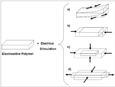
These properties are not exclusive of one type of polymer, but several types of polymeric materials may exhibit some kind of electromechanical response when subject to an electric field. Microscopically, they all may respond in different ways, but macroscopically they tend to deform, having sudden changes in their shape or their volume due to the electrical stimulation. Fig. 2.1 shows some basic responses that may be achieved by some types of electroactive materials.
Fig. 2.1. Some examples of the possible deformations achieved by a stimulated electroactive polymeric material. a) Contraction of a side and expansion of the counter-side creating a bending deformation. b) Contraction (or expansion) in one direction causing a change in volume. c) Contraction (or expansion) in all directions causing a change in volume. d) A redistribution of the material’s volumes to produce a change in its shape.
[image:25.612.192.431.383.563.2]force which produces a deformation in the material structure. This has lead researchers to classified EAP based on their deformation mechanisms. Although they all will response to an electrical signal or field, the reasons for this may vary from one type of EAP to another. So they are usually divided into two principal groups: Electronic EAP and Ionic EAP.
Electronic EAP’s are those that exhibit effects driven by an electric field or Coulomb
forces. Ionic EAP’s present displacement and/or volume change due to a different mechanism that the Electronic ones. These Displacements, induced by electric field, are due to molecule movements or diffusion of ions between polymer’s chains [2.1, 2.2].
It is to note that in most cases, the material will shows just one of the different kinds of deformations explained in the figure 2.1; and the deformation is strongly related to the polymer, its chemical structure, its macroscopic configuration, environment, and some other factors.
2.2.2. History in the research of EAP’s
As everything has a beginning, the history of how the study electroactive polymeric materials reached to what it has become today is the result of decades of research within the behavior of several materials put into test for their particular properties; as well as for their potential applications. This section is explained as a chronological review in the scientific background of the EAP. It starts more than a hundreds years ago, and continues to our days with still many things to be done, but still several references which are important for the material identification. The chronology in this field is explained as follows:
1899. A few years later, M.P. Sacerdote continues with Roentgen’s experiments and adds a mathematical formulation of the response obtain from the electric field. This study relates the material’s stress obtain when activated by the electrical field [2.2, 2.4]. This is one of the oldest known characterizations of the electroactive phenomenon present in a polymeric material.
1925. Several years later, polymers that present a piezoelectric behavior, and then called electrets, were observed by M. Eguchi [2.2, 2.5]. As in other kind of piezoelectric materials such as ceramic, these polymers present a linear deformation due a spontaneous polarization happening within the polymer structure.
1949. From all the previous research, other mechanisms such a chemical, thermal, or pneumatic were arising at the same time. The response of certain polymer studied by A. Katchalsky, as they were activated by acid or basic solutions, showed reversible deformation similar to the contraction and expansion mechanics of biological muscles. Therefore, a scientific interest of imitating these mechanisms was created [2.2, 2.6].
1966. The discovery of new polymers enabled the development of synthetic materials that could imitate biological muscles. The convenience and practical results obtained from electrical stimulation raises the interest among researchers for electroactive materials [2.2, 2.7]. It is to note that during this time, polymers are also known to be able to response to thermal, pH, magnetic, pneumatic, changes just as with the potential difference in an electric field [2.2]. However, most of these other materials are not developed further, or become less important.
1992. The characteristics of ionic polymer-metal composites are discovered as electroactive polymers by three research groups Oguro et al in Japan, and Shahipoor and Sadeghipour et al in the United States [2.9 – 2.11]. This represented a major advance in a time when electronic EAP seem to be more practical than ionic because of their fast response features.
1995. The study of conductive polymers, conducted by T.F. Otero, began as candidates for eletroactive materials using redox cycles for ion-exchange. This work is develop until 1998 with Otero and Sasiñena, where the synthesis techniques to obtain doped materials are refined for the production of mechanical actuators [2.12, 2.13].
2001. The first recollection of the work done so far, Electroactive Polymers as Artificial Muscles – Reality and Challenges, is gathered and edited by Y. Bar-Cohen to be
published in the SDM annual conference and as a book [2.1]. This publication collected information of the studies done over the years up to that date, representing a presentation the former state-of-the-art in EAP materials.
2.2.3. IPMC as the state-of-the-art in EAP
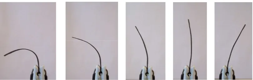
Ionic polymer-metal composites (IPMC) are ionic EAP. They constitute one of the major parts in the current advances in EAP. It is now well documented that ionic polymers in a composite form with a conductive medium such as a metal can exhibit large dynamic deformation if suitably set in an electrode and placed in a time-varying electric field. Currently this type of materials conform the up-to-date progress in electroactive polymer for application in short and mid term research and development. Conversely, dynamic deformation of such ionic polymers produces dynamic electric fields across their electrodes built in the same polymer; giving it a second feature to its actual properties. IPMC materials show great potential as soft robotic actuators, artificial muscles and dynamic sensors in the micro-to-macro size range [2.17].
Fig. 2.2. Successive photographs of an IPMC strip that shows very large deformation (up to 4 cm) in the presence of low voltage. Note that t = 0.5 s, 2 V applied. The sample is 1 cm wide, 4 cm long and 0.2 mm thick. [2.17]
There are a number of dynamic processes (e.g., ion migration, water diffusion) taking place in IPMC actuation despite that the exact mechanisms are still a subject of active research [2.18]. Though the bending-like deformation shown in figure 2.2 is one of the most seen in these materials, it has been known of other configurations that may help achieve different effects of actuation; leading to the manufacture of other original forms such as rods, multi-claw grippers, and some surface arrangements that, when cut in an specific patterns, are able to achieve different forms [2.19].
the end of a polymer chain), is replaced with a metal ionic cation (i.e. Na+, Li+). These cations will dissociate in water, so that terminal groups will have a negative charge and at the same time there will be an excess of free cations in the material. Since water molecules are dipoles, they orient themselves in electromagnetic field and attach to the free metal cations. When an electric field is applied, it causes an electric current which means that cations start to move to one side of the material causing expansion of the material from one side and contraction from the other side. The bent formation is an imbalanced situation. Water starts to diffuse in the opposite direction and the polymer sheet relaxes after some time. [2.20]
These materials do not keep their position under direct current. At the same time they are not as strong as electronic EAP and require from dozens to several hundred mA of current. When polarity of the electric field is changed, the muscle bends in the opposite direction since the cations always move towards the negative electrode. This is a specific property of all ion-conducting polymers (electronic polymers produce only unipolar actuation independent of the voltage polarity) [2.20].
Recently, much demand has been grown of soft actuators with bio-mimetic motions, which can be controlled by a small electric signal in various fields such as humanoid robotics, medical devices, and so on. Since their discovery, it has been noticed that the composite is capable of responding to an AC voltage in the ranges of 1 - 4V with a frequency of in the ranges of 100 – 1000mHz. The material is durable and the lifetime of the response is quite long, making then useful typically for more than 10,000 cycles [2.21].
2.2.4. Identification of the materials that compose an IPMC
1) Perfluorinated alkenes with short side-chains terminated by ionic groups (typically
sulfonate or carboxylate (SO−3 or COO−
) for cation exchange or ammonium cations for anion
exchange). The large polymer backbones determine their mechanical strength. Short side-chains provide ionic groups that interact with water and the passage of appropriate ions.
2) Styrene/divinylbenzene-based polymers in which the ionic groups have been substituted from the phenyl rings where the nitrogen atom is fixed to an ionic group. These polymers are highly crosslinked and are rigid.
In perfluorinated alkenes there are relatively few fixed ionic groups. They are located at the end of side-chains so as to position themselves in their preferred orientation to some extent. Therefore, they can create hydrophilic nano-channels, so-called cluster networks. Such configurations are completely different in other ionic polymers such as styrene/divinylbenzene families, which their ability to expand (due to their hydrophilic nature) is limited by cross-linking. For these reasons, it is considered that perfluorinated alkenes are more suitable to be used in the preparation of the IPMC [2.17].
Figure 2.3. Structure of perfluorinated polymers a) Nafion® and b) Flemion®. The side chains present sulfonate and carboxyl ionic groups in a) and b) respectively for cationic exchange, where +X can be any suitable counter-ion.
It has been noticed that the effectiveness of these materials to produce an IPMC is the result of the exchange and mechanical properties of perfluorinated polymers. The ion-exchange part is important not only for the preparation procedure of the IPMC, but also is important to achieve the deformation phenomenon in the material. The mechanical properties in the other hand become crucial in order to have a suitable actuator. For example, another porous ionic polymer membrane such as P(AN-co-SSS), where the presence of sulfonic acid groups makes it suitable in the ion-exchange part, is not suitable in its mechanical properties because of its acrylonitrile back bone structure. Thus, the preparation procedure uses Nafion ion-exchange material as the base polymer for the IPMC.
2.3. ABOUT OTHER MODELS FOR THE DEFORMATION IONIC POLYMER-METAL COMPOSITES FOUND IN LITERATURE
Due to their relatively recent discovery, several of the phenomena associated to the IPMC are still under active research. It is observed that, in general, a number of experimental procedures to measure the variables associated to the bending, as well as the phenomena considered during this action, are still in a way of proposing different approaches to model the particular features in IPMC.
For example, considering only the report advances as far as the year 2000 [2.24], de Gennes, Okumura, Shahinpoor and Kim [2.25] presented the first phenomenological theory for sensing and actuation in IPMC based on linear irreversible thermodynamics, with two
driving forces (E and a water pressure gradient ∇p) and two fluxes (electric current and water
current). Asaka and Oguro [2.26] discussed the bending of polyelectrolyte membrane-platinum composites by electric stimuli and presented a theory on actuation mechanisms in IPMC by considering the electro-osmotic drag term in transport equations.
Nemat-Nasser and Li [2.27] presented a modeling on the electromechanical response of ionic polymer-metal composites based on electrostatic attraction/repulsion forces in the IPMC. Later, Nemat-Nasser [2.28] presented a revised version of their earlier paper and stressed the role of hydrated cation transport within the clusters and polymeric networks in IPMC. Nemat-Nasser and Wu [2.29] have presented a discussion on the role of back bone ionic polymer and in particular sulfonic versus carboxylic ionic polymers, as well as, the effect of different cations such as K+, Na+, Li+, Cs+ and some organometalic cations on the actuation and sensing performance of IPMC’s.
All this freedom found in the formulation of the mathematical aspects which try to explain such a particular feature found in IPMC materials, somehow had made many engineers to choose for actual experimentations in order to have a basic understanding of the electroactive phenomenon in order to use it for specific design purposes; which consumes time and is still far to contribute to the establishment of standards in the field of giving applications to the material.
2.4. MODELING OF THE DEFORMATION PHENOMENON IN IONIC POLYMER-METAL COMPOSITES
2.4.1. Modeling of the displacement as a deforming beam
The modeling begins with the characterization of the system to be analyzed in its external behavior. The configuration of the IPMC is the same as a beam in a cantilever state, having one end fixed and the other end free for movement. When a load is applied to the system, a reversible deformation is produced. Where P is the load (virtual) responsible for the movement and δ is the maximum displacement obtained from the deformation; taking in
account the existence of a reciprocal deformation when the system enters relaxation after the load disappears.
The deformation of the system may be expressed mathematically as a function of the load and the material properties along the length of the beam. By Hooke’s law, it is known that the deformation over a beam system as presented in figure 2.4 is given by:
EZ PX
E =
= ( )
)
(χ σ χ
ε (2.1)
Where σ(χ) is the bending stress on a beam or strip at a distance X from the point of application of the load to its fixed end. E is the modulus of elasticity of the material which composed the beam. Z is the section modulus, which is constant while the geometric shape does not change.
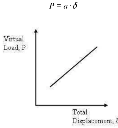
In this case, there is not a load P responsible for the displacement δ. However, this
load exists as a reaction. For this reason it will be called virtual load. On the other hand, it is known that the displacement δ is directly proportional to the virtual load P.
δ
⋅
=
a
[image:35.612.203.398.399.609.2]P
(2.2)Fig.2.5. Linear relationship between the virtual load P and the total displacement δ.
δ
ε
=
ZE aX
or
ε
δ
=
aX ZE
(2.3)
Where K is equal to:
aX ZE
K =
It is observed here that a and E are parameters that depend on the material. Also X and
Z depend on the geometry and the position of the material. In eq (2.3) the K is called a factor
for the virtual, geometric, and material conditions. At normal conditions, a and E are constant as the material does not change its properties. In this case, however, the material will change its composition properties at the diffusion zones, and thus a and E will also change. Nevertheless, to begin the modeling it is considered that these parameters will remain constant.
2.4.2. Determining the factor K for the effect of the presence of the ion
After establishing the principles for the external behavior for the bending beam system, the following states regarding the internal changes within the material are considered:
The diffusion of particles (ions and waters molecules) from a state A to B promotes the volumetric expansion in one side of the cross section of the thickness, and a volumetric contraction at the other side. In a particular region at a state A’, a lower concentration of the counter-ion is observed. After the migration it is possible to see that a larger volume of particles or counter-ions in the same region or space previously at state A’ has allocated there, which turned into a state B’. This change let us relate the diffusive process as a phase transformation induced by an external factor, more than by transport phenomena. Since one of the side will have a larger concentration than the other, A’ and B’ may be consider two phases coexisting at the same time in the material. It is by this that the following hypothesis may be proposed:
The change in the physical-chemical state due to ion transport diffusion as a
consequence of the application of a potential difference in an ionic polymer-metal composite,
IPMC, is considered as a type of phase transformation in the material, induced by said
potential difference.
That way, the following behavior regarding the ionic migration within the polymeric cross section, while increasing the potential to diffuse by means of a voltage (V), should be seen:
Where, Vfi is the volumetric fraction of the counter-ion present or missing in the material. The volumetric fraction is expressed by the next equation:
T i i f
V V
V = (2.5)
having,
0 1≥Vfi ≥
Where, Vi is the volume occupied by the counter-ion inside the polymer and VT is the total volume in the material.
Since most of the attention is towards the surface that expands, where the most of the counter-ions migrate, and because of the reciprocity of the phenomenon, it is possible to just consider the surface that expands. This way, by constant frequency (ν) conditions and the
migration of a certain size of counter-ion specie, Vfi should be able to show the following behavior:
Fig. 2.8. Behavior of the volume fraction Vfi at the expanding side of the cross section at a specific
So, at the end, for other values of frequency conditions, the following is obtained:
Fig. 2.9. Behavior of the volume fraction Vfi at the expanding side of the cross section at several frequency
conditions.
In order to calculate the different curves of Vfi within different voltages and frequency conditions, the model of phase transformation developed by Cortes [2.33, 2.34] may be analogically applied for these conditions in such a way that the following equation is obtained:
1
1
− −
+ =
B
C i
f
V V
V (2.6)
Where V is the potential difference in Volts, VC is a characteristic potential difference
Fig. 2.10. The characteristic voltage VC is the value of potential difference at which the system is at 50% of
transformation.
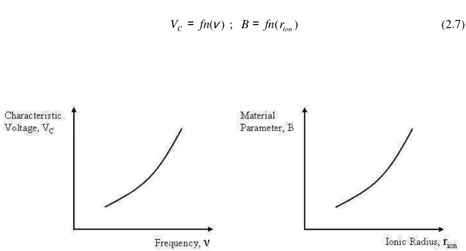
Then, it may be proposed that VC and B are found in terms of the frequency (ν) and the
distinctive characteristic of the embedded counter-ion, like the ionic radius (rion), respectively. This is:
) (ν fn
VC = ; B= fn(rion) (2.7)
Fig. 2.11. The possible behaviors of characteristic voltage VC vs. Frequency and the material parameter B
By substituting eq(2.7) into eq(2.6), there is 1 ) ( ) ( 1 − − + = ion r fn i f fn V V
ν (2.8)
The eq(2.8) represents the volumetric fraction of the new transformed ionic phase. This means that it represents the volume fraction of the immigrated ions by the effect of the potential difference applied to the IPMC and the type of counter-ion being transported.
Retaking eq(2.3), and emphasizing in the displacement of the strip in terms of the determination over the surface generated by the virtual load, and which it may be justified to be equal to the increase in the volume provided by the diffusion of the ionic phase in the surface of the strip, the total displacement of the previous external beam system may be expressed as:
ε
δ =K (2.9)
Fig. 2.12. The total displacement as a linear relationship between the factor K and the strain ε.
When the material changes, the following behavior may be expressed graphically as:
Fig. 2.13. Behavior of total displacement δ vs. strain ε at different conditions of potential difference.
Where the change in the material, in terms of the of the volume fraction of the contained ion specie, is observed as a particular composition of the achieved configuration.
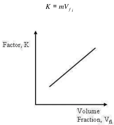
This way, each slope is a particular function of the type of material under constant geometric conditions. Thus,
i f mV
K = (2.10)
Where m is a proportionality constant. And so, eq(2.10) is specify as:
) ,
( rion
fn m
K = ⋅ ν (2.11)
Substituting eq. (2.8) in eq. (2.11), it results:
1 ) ( ) ( 1 − − + ⋅ = ion r fn fn V m K
ν (2.12)
Which is the factor needed for eq. (2.3). It may be noticed that the factor K in eq.
(2.12) is a function of the potential difference, the frequency, and the ionic characteristic. Also
the proportionality constant m and the volume fraction of the ion play a role in the equations.
Eq. (2.12) helps confirm that the factor K is parameter strongly dependant on the
material properties and the operational conditions; so that it becomes a critical parameter that enables to distinguish the material under the mechanical effect of deformation-displacement of
the same. However, since VC and B in eq.(2.6) still do not have a physical meaning, they are
considered here just as two values that vary with frequency and ionic radius respectively.
2.4.3. Determining the deformation as a function of the operational conditions
Parting from eq.(2.3) and substituting in eq.(2.12), it is given that
1 1 − − + ⋅ ⋅ = B C V V m ε
Considering the deformation over a section of the surface as a variable with a very small magnitude and practically constant for the displacements obtained experimentally, it may be established that:
= ⋅
= ε
α m constant
where, 1 1 − − + ⋅ = B C V V α
δ (2.15)
Eq. (2.15) represents the constitutive model that let us predict the total displacement from the bending deformation action in the IPMC strip. In order to use this constitutive model,
the three parameters, α, VC, and B must be solved; which is the purpose of the steps to follow
in the methodology established in the previous chapter.
After the solution of eq. (2.15) for the given parameters, by eq. (2.3) an expression of strain in terms of the geometry of the strip, the characteristics of the material, and the operational conditions may be obtained.
1 1 − − + ⋅ ⋅ = B C V V ZE aX α
ε (2.16)
On the other hand, by relating eq. (2.3) and eq. (2.16) it is possible to determine the Modulus of elasticity for the material as a function of the operational and ionic characteristics present in the material.
1 1 − − + ⋅ = B C V V Z aXm
Eq. (2.17) confirms that the compound material, and particularly of variable composition even under control, possesses also variable mechanical properties; being this one of the most distinctive characteristics of a functional and reconfigurable material. The
Modulus of elasticity E traditionally is a material constant, however in eq. (2.17) it is
expressed as a function of the factors related to the external and internal changes in the system. In numerical simulation, it may serve the purpose of predicting the changes in the Modulus of elasticity due to the change in the conditions given to the material.
2.5. CHAPTER REMARKS
In this chapter a constitutive model for the bending deformation of an electrically induced IPMC is proposed. In order to fulfill this objective, an identification of the characteristics of EAP materials is done in order to understand the features by which these polymers are distinguished from other functional materials. The identification process explained the difference between the mechanisms of the electroactive phenomenon in some EAP. These differences revealed the existence of two major behaviors which divide EAP into two main groups: Electronic and Ionic EAP.
The background in the research of EAP traced the advances since EAP were discovered. Using this information, the IPMC, an ionic EAP, is found within the state-of-the-art in EAP materials.
By briefly mentioning the current advances in modeling the bending behavior (along with other effects) of the IPMC, it is observed that several approaches done in the recent years still open a wide area of opportunity, where no concrete standards are currently present, in order to be used for engineering purposes.
transformation at one of the sides of the cross section of the IPMC. The phase transformation in this case is used to correlate the internal change in the volume fraction of the contained
counter-ions inside the polymer as a function of the applied voltage V, adjusted by a
characteristic voltage VCwhich depends on the frequency conditions, and a parameter B which
is a function of the inner constitution of the material base on the ionic content.
2.6. REFERENCES
[2.1] Bar-Cohen, Yoseph; Electroactive Polymer (EAP) Actuators as Artificial Muscles – Reality, Potential, and Challenges, SPIE Press, Bellingham, Washington, 2001.
[2.2] Bar-Cohen, Y., Electroactive Polymers as Artificial Muscles – Reality and Challenges, Structures, Structural Dynamics, and Materials Conference (SDM), Gossamer Spacecraft Forum(GSF), held in Seattle WA, April 2001.
[2.3] Roentgen, W.C., About the changes in shape and volume of dielectric caused by electricity, Annual Physics and Chemistry Series, Vol. 11, pp. 771-786, 1880.
[2.4] Sacerdote M. P., On the electrical deformation of isotropic dielectric solids, Journal of Physics, 3 Series, t, VIII, 31, 1899, pp. 282-285.
[2.5] Eguchi M., On the Permanent Electret, Philosophical Magazine, Vol. 49, 1925, pp. 178.
[2.6] Katchalsky, A., Rapid Swelling and Deswelling of Reversible Gels of Polymeric Acids by Ionization, Experientia, Vol. 5, 1949, pp. 319-320.
[2.7] Steinberg, I. Z., Oplatka, A., Katchalsky, A., Mechanochemical engines, Nature, Vol. 210, 1966, pp. 568-571.
[2.8] Kawai, H., The Piezoelectricity of Poly(vinylidene Fluoride), Japan Journal of Applied Physics, 1969, Vol. 8, p. 975.
[2.9] Oguro, K., Kawami, Y., Takenaka, H., Bending of an ion-conducting polymer film-electrode composite by an electrical stimulus at low voltage, Trans. Journal of Micromachine Society, Vol. 5, 1992, pp.27-30.
[2.10] Shahinpoor, M., Conceptual design, kinematics and dynamics of swimming robotic structures using ionic polymeric gel muscles, Smart Materials and Structures, Vol. 1, No.1, 1992, pp. 91-94.
[2.11] Sadeghipour, K., Salomon, R, Neogi, S., Development of a novel electromechanically active membrane and ‘smart’ material based vibration sensor/damper, Smart Materials and Structures, 1992, pp.172-179.
[2.12] Otero, T. F., Grande, H., Rodriguez, J., A new model for electrochemical oxidation of polypyrrole under conformational relaxation control, Journal of Electroanalytical Chemistry, Vol. 394, 1995, pp.211-216.
[2.13] Otero, T. F., Sansiñena, J., Soft and wet conducting polymers for artificial muscles, Advanced Materials, Vol. 10, No.6, 1998, pp. 491-494.
[2.15] Malone E., Lipson H., Freeform Fabrication of Electroactive Polymer Actuators and Electromechanical Devices, Proceedings of the 15th Solid Freeform Fabrication Symposium, Austin TX, 2004, pp.697-708.
[2.16] Ramos, M.M.D., Correia, H.M.G., Lanceros-Méndez, S., Atomistic modeling of processes involved in poling of PVDF, Computational Materials Science, Vol. 33, No. 1-3, 2005, pp. 230-236.
[2.17] Shahinpoor, M., Kwang, J. K., Ionic polymer-metal composites: I. Fundamentals, Smart Materials and Structures, Vol. 10, 2001, pp.819-833.
[2.18] Chen, Z., Tan, X., Shahinpoor, M., Quasi-static Positioning of Ionic Polymer-Metal Composite (IPMC) Actuators, Proceedings of the 2005 IEEE/ASME, International Conference on Advanced Intelligent Mechatronics, Monterey, California, USA, 24-28 July, 2005.
[2.19] Kim, K.J., Shahinpoor, M., A novel method of manufacturing three-dimensional ionic polymer-metal composites (IPMCs) biomimetic sensors, actuators and artificial muscles, Polymer, Vol.43, No.3, 2002, pp. 797-802.
[2.20] Punning, A., Anton, M., Kruusmaa, M., Aabloo, A., An Engineering Approach to Reduced Power Consumption of IPMC (Ion-Polymer Metal Composite) Actuators, The 12th International Conference on Advanced Robotics (ICAR2005), Seattle, 2005.
[2.21] Asaka, K., Nakabo, Y., Muka, T., Luo, Z.W., Response Function of Polymer Electrolyte Actuators, SICE Annual Conference in Fukui, Fukui University, Japan, August 4-6, 2003.
[2.22] DuPontTM Nafion® PFSA Membranes http://www.dupont.com/fuelcells/pdf/dfc101.pdf [Accessed April 2006].
[2.23] Asahi Glass, Co. LTD. R & D Flemion® http://www.agc.co.jp/english/rd/topics_04.html [Accessed April 2006].
[2.24] Shahinpoor, M., BIONIC: Soft Plastic Robots and Artificial Muscles, Artificial Muscle
Research Institute (AMRI), Division of Neurological Surgery, School of Medicine, University of New Mexico, Albuquerque, New Mexico, USA.
[2.25] de Gennes, P. G., Okumura, K., Shahinpoor, M., and Kim, K.J., Mechanoelectric Effects in Ionic Gels, Europhysics Letters , Vol. 50, No.4, 2000, pp. 513-518.
[2.26] Asaka, K., and Oguro, K., Bending of Polyelectrolyte Membrane Platinum Composites By Electric Stimuli, Part II. Response Kinetics, J. Electroanalytical Chemistry, vol. 480, 2000, pp. 186-198.
[2.27] Nemat-Nasser, S., and J. Y. Li, Electromechanical Response of Ionic Polymer-Metal Composites, J. Applied Physics, Vol. 87, No. 7, 2000, pp. 3321-3331.
[2.29] Nemat-Nasser, S., and Wu, Y., Comparative Experimental Study of Ionic Polymer-Metal Composites With Different Backbone Ionomers And In Various Cation Forms, J. Applied Physics, Vol. 93, 2003, pp. 5255-5267.
[2.30] Tadokoro, S., An Actuator Model of ICPF For Robotic Applications On the Basis of Physico-Chemical Hypotheses, Proc. IEEE, ICRA, 2000, pp. 1340-1346.
[2.31] Tadokoro, S., Yamagami, S., Takamori, T., and Oguro, K., Modeling of Nafion-Pt Composite Actuators (ICPF) by Ionic Motion, Proceedings of the SPIE, SPIE Publication, Vol. 3987, 2000, pp. 92-102.
[2.32] Tadokoro, S., Takamori, T., and Oguro, K., Application of the Nafion-Platinum Composite Actuator, Proceedings of the SPIE, SPIE Publication, Vol. 4329, 2001, pp. 28-42.
[2.33] Cortes, J.A., Analysis of Flow Stress and Martensitic Phase Transformation in the Austenitic Stainless Steels Under Cold Working, Doctor Course Thesis, Hiroshima University, Japan, March, 1993.
3. PREPARATION OF A THREE-LAYERIONIC POLYMER-METAL COMPOSITE MATERIAL BY METAL DEPOSITION WITH
OXIDATION AND REDUCTION REACTIONS
3.1. INTRODUCTION
The following chapter concerns the preparation of the IPMC. The objective is to construct a set of conducting electrodes over the surface of an ion-exchange membrane (Nafion®) to obtain the electroactive material that is used further in the work for experimentation, and solution of the constitutive equations proposed. The identified materials from the previous chapter are subject to a preparation procedure through chemical reactions in order to produce the IPMC material. Then a physical characterization of the prepared materials is done using Scanning Electron Microscopy (SEM) and Atomic Forcé Microscopy (AFM) in order to analyze the formation and morphology of the of the metallic layers in the IPMC.
The result from the work done in this chapter is a completely functional IPMC sample that may be used for the experimentation stage to follow. The results from the characterization are discussed at during the present chapter.
3.2. PREPARATION PROCEDURE FOR IPMC
introduced to carry out a reducing reaction similar to the first on, and build a thicker layer in addition to the initial platinum layer formed by the first compositing process.
3.2.1. Surface roughening and cleaning of the membrane
The purpose of this previous step is to prepare the surface of the polymer membrane and clean any impurities that may be present over the same. The roughening of the membrane has been done before by several techniques [3.2, 3.5]. The membrane could be roughened by using a sandblaster with an abrasive agent in other to obtain a fine roughening, or simple emery paper may be used over the membrane. It is to be noticed that the morphology of the surface will be importantly affected by any technique applied, and the surface of one sample may not be the same as to another one even after using the same technique. However, it has also been observed through experimentation that the platinum will still have a good adhesión to the surface even though no roughening is made. For further comparison, some samples are prepared applying roughening, and others are just cleaned leaving the membrane as received firom manufacturer.
After that, either the roughening is done on the surface or not, all the impurities present in the membrane must be cleaned. To do so, a solution of hydrochloric acid (HCl) is prepared with a 2N concentration. The membrane in the HCl solution is then heated up to boiling temperature for 30 minutes. After this, the membrane is rinse using deionized water. The process is repeated, but instead of HCl the membrane is introduced in deionized water and boiled for 30 minutes in order to remove the acid remnants inside the membrane. The cleaned polymer may be used now for the next process.
3.2.2. Ion-exchange process for platinum absorption