AN INTENSITY - BASED BOUNDARY ELEMENT METHOD FOR ANALYZING
BROADBAND HIGH FREQUENCY SOUND FIELDS IN ENCLOSURES
PACS REFERENCE: 43.55.Br
Franzoni, Linda; Rouse, Jerry Duke University
Department of Mechanical Engineering and Materials Science PO Box 90300
Durham, NC 27708-0300 USA
TEL: 919-660-5436 FAX: 919-660-8963 E-mail: [email protected]
ABSTRACT
An intensity-based boundary element method replaces enclosure boundaries with a continuous distribution of broadband uncorrelated sources, which are described in terms of intensity vectors and directivity functions. These directivity functions account for the local correlation between neighboring infinitesimal sources and are used to include specular reflections. Boundary conditions for radiating and absorbing surfaces are expressed in terms of intensity. This boundary element differs from the classical version in that the element size is large compared to an acoustic wavelength and equations are not solved on a frequency-by-frequency basis. The method is demonstrated for sample enclosures with comparison to exact analytical and experimental results and good agreement is obtained. [Sponsored by the U. S. National Science Foundation]
INTRODUCTION
The prediction of sound pressure levels in the interiors of vehicles is of importance to the design of such spaces. The design must consider passenger comfort, as well as functionality; this comfort includes the elimination of unwanted noise and the reduction of remaining noise levels. Central to the design process is the availability of computationally efficient modeling tools that enable one to predict the outcome of different design decisions before they become reality.
The focus of this work is the modeling and analysis of broadband high frequency sound fields in enclosures (such as vehicles or rooms) whose boundaries may be moderately damped, i.e., sound fields which are not necessarily diffuse. However, because of the quasi-randomness of the sound field (due to the large number of responding modes in the bandwidth of interest) those simplifying assumptions which are usually used to allow the variable of interest to be energy rather than sound pressure still apply. The rationale behind these assumptions in the high frequency regime is discussed by many authors, for example, Kuttruff [1], Le Bot [2], or Lyon [3].
PREVIOUS WORK
Energy-based methods for analyzing broadband high frequency sound fields have been evolving in recent years. The most common energy-based method for predicting steady-state sound pressure levels in high frequency applications is Statistical Energy Analysis (SEA), which has been in use since at least the mid-1970’s. The text by Lyon [3] is the standard reference for this method. Individual papers involving the use of SEA for predicting sound pressure levels are too numerous to mention. In the late 1980’s, Nefske and Sung [4] developed an energy-based finite element approach for dynamic systems, resulting in a diffusion equation for the power flow in beams. Bernhard and colleagues [5-9] extended their energy flow analysis work to various other dynamic systems and subsequently developed an Energy Finite Element Method (EFEM). The aforementioned approaches assume a dissipative medium, and in theory, will fail if the medium is non-dissipative. Le Bot and colleagues [10,11], as well as Langley [12, 13], have examined the relationship between the heat conduction equation that was the basis for much of the previous energy flow work and a wave approach solution. They found some discrepancies between these approaches and in Ref.[11] an alternative energy approach is suggested.
Energy-based approaches which do not result in a diffusion equation have also been studied recently. Work by Carroll and Miles [14], Miles [15], Kuttruff [1], Le Bot and Bocquillet[2], and Le Bot[16] have involved analysis of high frequency diffuse sound fields. In each of these cases, Lambert’s Law was applied to describe the reflections from the boundaries; specular reflection effects were not included. The main difference between all of the previous work and the work presented here is the consideration of specular reflection rather than Lambertian reflection. For certain geometries and partially diffuse situations, an image source method has been used by Kuttruff [17] in combination with the diffusely reflecting boundary condition in order to include some effects of specular reflection. The image source method was not used in the work presented here. Franzoni, Bliss, and Rouse [18] have shown that the acoustic field in an enclosure can not be modeled by uncorrelated plane waves, unless the sound field is truly diffuse (i.e., no energy gradient is present). In their work (and this paper), the assumption of plane waves is abandoned and uncorrelated spreading waves are used instead. In addition, the uncorrelated sound sources that comprise the boundaries of the enclosure are directional. The role of the directivity function is two-fold: it includes the very local effects (within a fraction of a wavelength) of correlation between neighboring sources, and it is used to account for specular reflection. It is the directivity function that makes this particular energy-based method so unique.
THEORETICAL DEVELOPMENT
A thorough derivation of the intensity-based boundary element is given in Ref. [18], therefore only the highlights of the derivation will be presented here. As previously mentioned, it was shown mathematically that for enclosures with reflective and absorptive surfaces, where energy is flowing, waves can not be both uncorrelated and planar. In the earlier work by others [Ref. 5-9], where plane waves are assumed to be uncorrelated, the addition of a dissipative term allows for a non-zero gradient of energy. However, in non-dissipative media, where the only energy loss is at the boundaries, it is physically incorrect to assume both plane waves and a lack of correlation.
In Ref.[18], the boundaries of the enclosure are replaced with broadband high frequency infinitesmal acoustic sources which are assumed to emit directional spreading waves. An integral equation over the boundary is derived for the mean-square pressure as a function of the distributed power (dW/dS) and directivity functions (D(θ)) and known source power, Ws.
This equation is discretized, and the integration is performed over boundary elements that are assumed to have constant strength (i.e., one source strength assigned to each element). The strength of each element is determined from a linear set of equations that come from the boundary conditions applied at the node (control point) of each element. The boundary condition is a statement of energy conservation: the power into the enclosure from the i element is equal to a sum of that reflected due to the power incident from all of the other elements, j, (the reflection coefficient associated with the i element times the incident power from each of the other boundary elements) plus that reflected due to any interior sources, s. The power associated with the i
element is therefore a function of all of the unknown source powers associated with the j elements, as well as their directivity functions and the angle of incidence from j to i. This condition is written, in terms of intensity, as:
(
)
(
)
∑
(
)
(
)
∑
⋅
θ
−
⋅
θ
−
=
⋅
≠ s1
s , i i s , i s , i i i
j
j , i i j , i j , i i i
i
I
n
I
R
z
,
n
I
R
z
,
n
r
r
r
r
r
r
(2)where
z
is the normalized boundary impedance, and R is the reflection coefficient.For an individual element, the same directivity pattern is assumed for all the infinitesimal sources distributed along that element. In two-dimensions, the directivity function is assumed to have the form:
( )
cos
[
f
f
cos
f
sin
...
]
D
φ
=
φ
0+
1φ
+
2φ
+
(3)where φ is the angle from the normal of the element. Using the iterative approach of Ref [18], the problem is solved first with only one term in the series, leaving only one unknown per element. Truncating the directivity function series to a single term satisfies power conservation and happens to represent Lambertian reflection. It is important to note that Lambertian reflection (i.e., a diffusely reflecting boundary) is not an assumption in the model. For subsequent iterations, the incident (and therefore, the reflected) intensity field is divided into sections. In 2-D the incident intensity is divided into right- and left- components, relative to the local coordinate system of the element. The normal component of intensity is also used. A relationship is derived between the components of intensity and the coefficients of the directivity function series expansion. Intuitively, one can see that if the incident intensity (and therefore, reflected intensity) is large in the normal direction compared to either of the side directions, the f1 term in the series expansion will be large, resulting in a significant cosine-squared contribution to the directivity. On the other hand, if the directivity is skewed to one side, the f2 term will account for left- or right- tipping of the directivity function. To solve for the unknown coefficients directly, rather than by an iterative scheme, the incident intensity needs to be written in terms of the series expansion from the beginning. The boundary conditions (including specular reflection) need to be applied to each element, resulting in equations that are functions of angle at each element. Applying orthogonality allows the equations to be separated into constituent equations, where there will be the same number of equations as unknowns.
RESULTS
Rectangular Two-dimensional Enclosure: Comparison with Exact Analytical Solution
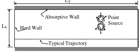
[image:4.612.156.397.137.226.2]A two-dimensional model problem, consisting of a rectangular enclosure with absorptive parallel walls along the lengthwise direction, and hard walls in the width-wise (shorter) direction, as shown in Fig. 1.
Figure 1. Description of 2-dimensional model problem with exact analytical solution
This is a problem that can be solved analytically, and was used for comparison with the BEM results. Figures 2 and 3 show comparisons between the exact analytical solution, averaged in one-third octave bands for different center frequencies, at different spatial locations along a trajectory. The data points representing the exact solution are averages of many points within a
representative quarter-wavelength around the center point. In Figure 2, there is only one interior sound source, whereas, in Figure 3, there are two interior sound sources. Notice that in between the sound sources in Figure 3, the boundary element method and the exact results do not agree very well. This is due to the correlation on the centerline between the two sources.
Figure 2. Different levels of absorption Figure 3. Case with 2 sources
Rectangular Three-dimensional Enclosure: Comparison with Exact Analytical Solution
A similar verification was performed for a three-dimensional model problem with two absorptive parallel walls and hard walls otherwise. Agreement between the boundary element results and the exact analytical solution was comparable to that of the two-dimensional case. In the three-dimensional case, the directivity function is expanded as a series of spherical harmonic functions (Legendre polynomials with unknown coefficients).
Point Source Hard Wall
Absorptive Wall L
L
x
y
Typical Trajectory
0.0 2.0 4.0 6.0 8.0 10.0 12.0 14.0 16.0 18.0
0 0.1 0.2 0.3 0.4 0.5 0.6 0.7 0.8 0.9 1
Dimensionless Y
Pbar^2*Ly/(rho*c*Wps)
BEM
Avg. Kcbar = 160
Avg. Kcbar = 320
Avg. Kcbar = 640
0.0 5.0 10.0 15.0 20.0 25.0
0 0.1 0.2 0.3 0.4 0.5 0.6 0.7 0.8 0.9 1
Dimensionless Y
Pbar^2*Ly/(rho*c*Wps)
BEM
[image:4.612.68.528.386.568.2]Irregular Two-dimensional Enclosure: Comparison with Experimental Results
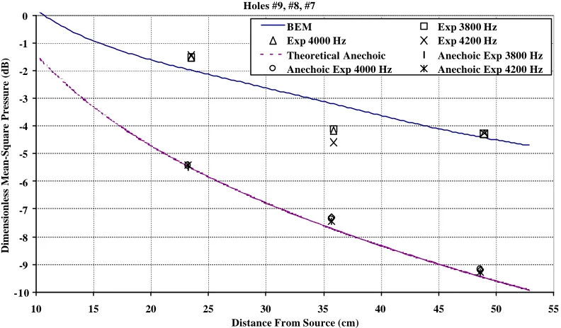
[image:5.612.148.460.184.348.2]In order to verify the method for an irregular geometry, an experiment was performed for a two-dimensional case, where the enclosure had no parallel side walls or right angles in-plane and was shallow out-of-the-plane relative to a half-wavelength. Measurements of sound pressure level were taken at points in the interior. The sound pressure levels were measured in octave bands and fractions of an octave band. A schematic of the experimental enclosure is shown in Figure 4. Results are currently being obtained for numerous spatial locations and different distributions of absorptive material. An example comparison is shown in Figure 5.
Figure 4. The experimental enclosure (top view). Dimensions in cm.
Figure 5. Comparison between 2-D experiment and BEM code.
Holes #9, #8, #7
-10 -9 -8 -7 -6 -5 -4 -3 -2 -1 0
10 15 20 25 30 35 40 45 50 55
Distance From Source (cm)
Dimensionless Mean-Square Pressure (dB)
BEM Exp 3800 Hz
[image:5.612.105.501.409.641.2]Two curves are shown in Figure 5, the curve with higher amplitude is a trajectory along a constant radial line from the source (see Fig 4). The second curve corresponds to the theoretical prediction of the direct field. The corresponding experimental data points are shown for the two cases: walls partially covered with absorptive foam, and an anechoic condition. Good agreement between the experiment and theoretical results is shown.
SUMMARY AND CONCLUSIONS
The intensity-based boundary element method that is presented here, containing specular reflection effects is an efficient and accurate means of predicting mean-square pressure levels on a spatially-averaged basis in a frequency band. Comparison between the BEM results and exact analytical solutions, where the parameters are known precisely (for example, boundary impedance, and spatial locations are explicitly given) show excellent agreement. Comparisons with experiment, where quantities such as impedance of wall coverings and precise spatial location may not be that well known, show fairly good agreement. In general, the method shows promise; further verification and development of the method is underway.
REFERENCES
[1] Kutruff, H. “Energetic Sound Propagation in Rooms,” Acustica, 83 (1997) 622-628.
[2] Le Bot, A. and Bocquillet, A., “Comparison of an Integral Equation on Energy and the Ray-Tracing Technique in Room Acoustics,” J. Acoust. Soc. Am., 108 (2000) 1732-1740.
[3] Lyon, R.H., Statistical Energy Analysis of Dynamical Systems: Theory and Applications, Cambridge, MA: MIT Press, 1975.
[4] Nefske, D. J. and Sung, S. H., “Power Flow Finite Element Analysis of Dynamic Systems: Basic Theory and Application to Beams,” J. of Vib., Stress, and Reliability in Design, 111 (1989) 94-100. [5] Wohlever, J. C. and Bernhard, R. J., “Mechanical Energy Flow Models of Rods and Beams,”
Journal of Sound and Vibration153 (1992) 1-19.
[6] Bouthier, O.M. and Bernhard, R. J., “Simple Models of Energy Flow in Vibrating Membranes,”
Journal of Sound and Vibration182 (1995) 129-147.
[7] Bouthier, O.M. and Bernhard, R.J., “Simple Models of the Energetics of Transversely Vibrating Plates,” Journal of Sound and Vibration182 (1995) 149-164.
[8] Bernhard, R. J. and Huff, J.E., “Structural-Acoustic Design at High Frequency Using the Energy Finite Element Method,” ASME Design Eng. Tech Conferences, DE-Vol.84-2, 1995, 565-570.
[9] Huff, J.E., Bernhard, R. J., “Prediction of High Frequency Vibrations in Coupled Plates Using Energy Finite Elements,” Proceedings of Inter-Noise, Newport, CA, July 10-12 1995, 1221-1226. [10] Inchchou, M. N., Le Bot, A., and Jezequel, L., “Energy Models of One-Dimensional, Multi-Propagative Systems, Journal of Sound and Vibration201 (1997) 535-554.
[11] Le Bot, A., “A Vibroacoustic Model for High Frequency analysis,” Journal of Sound and Vibration211 (1998) 537-554.
[12] Langley, R.S., “Analysis of Beam and Plate Vibrations by Using the Wave Equation,” Journal of Sound and Vibration 150 (1991) 47-65.
[13] Langley, R.S., “On the Vibrational Conductivity Approach to High Frequency Dynamics for Two-Dimensional Structural Components,” Journal of Sound and Vibration, 182, (1995) 637-657. [14] Carroll, M.M., and Miles, R.N., “Steady-State Sound in an Enclosure with Diffusely Reflecting Boundary,” J. Acoust. Soc. Am. 64 (1978) 1424-1428.
[15] Miles, R.N., “Sound Field in a Recttangular Enclosure with Duffusely Reflecting Boundaries,”
Journal of Sound and Vibration92 (1984) 203-226.
[16] Le Bot, A., “A Vibroacoustic Model for High Frequency Analysis,” Journal of Sound and Vibration211 (1998) 537-554.
[17] Kuttruff, H., “Stationary Propagation of Sound Energy in Flat Enclosures With Partially Diffuse Surface Reflection,” Acustica, 86 (2000) 1028-1033.