Probabilistic Multicast Trees
David A. JohnstonRockwell Automation, dajohnston@ra.rockwell.com Cleveland, Ohio 44124
David R. McIntyre
CS Department, Cleveland State University Cleveland, Ohio 44101
Francis G. Wolff
EECS Department, Case Western Reserve University Cleveland, Ohio 44106
Christos A. Papachristou
EECS Department, Case Western Reserve University Cleveland, Ohio 44106
Abstract
Delivery of the same data content to many clients simultaneously over the Internet continues to be a challenging problem. Multicasting using a single tree structure for data distribution has been shown to be an effective methodology for distribution of data. Using the tree structure to distribute data relieves the source node from the burden of trying to unicast to each client and is efficient because the data delivery burden is distributed over all the participating client nodes. Using multiple tree multicasting further distributes the transmission burden over more participating client nodes and it improves the efficiency of the data distribution. Multiple multicast trees can also be used to manage dynamic behavior of the underlying network. We introduce a methodology which improves data delivery latency and efficiency upon current multiple tree multicast methods. This methodology incorporates a feedback mechanism, randomness and a weighted tree selection mechanism to determine the most efficient multicast tree for multicasting.
Keywords
: Application-level multicast, Reliable Multicast, Adaptive tree selection, Content distributionIntroduction
Researchers have long sought ways to distribute the same data to many clients efficiently. Early methods examined hardware methods to distribute this data which resulted in IP multicast. Unfortunately, IP multicast has many limitations that prevent it from being widely used on the Internet. Saltzer[11] argued that the network should be kept as simple as possible and for any multicasting that the intelligence resides at the application layer. Application layer multicast is the fundamental principle of the “end to end” argument that Saltzer proposed. Many researchers [1][6][3][5] focused on ways to distribute data using multicast overlay networks formed as trees where a multicast tree structure is overlaid on the physical network. The main issue with a single multicast tree
is that node failures cause long delays and performance issues as the data is delivered. By node we mean a computing device which can both receive and relay data.
Most of the multicasting applications supported repair of the multicast tree as node failures occurred. In some cases, probing methods were used to improve the performance of the tree and by design, repair the tree if needed [6]. However, the repair and probing methods were performed at a much slower rate than the transmission of the data stream to prevent extra burden on the multicast tree. To address client failures, several methods were used such as using redundant paths, replicating data randomly or using wholly redundant trees [1].
Other methods build multiple multicast trees and use them all equally. This methodology is called multiple tree multicasting. Multiple multicast trees have been shown to benefit the multicasting application where they increase throughput and reliability [2][4][12][13]. Using multiple trees increases the efficiency of data delivery over a single multicast tree because it is using alternate routes. However, multiple multicast trees have issues as well such as lost nodes and congested routes. Researchers have devised solutions to address these issues such as additional replication of data packets beyond the normal multicast distribution, forward error correction FEC [9] and multiple description coding MDC [7]. However, these schemes use additional network bandwidth.
a multiple multicast tree system built upon Scribe [5]. Split-stream builds several Scribe trees to form the multiple multicast tree system. Scribe is a single tree multicast system built upon Pastry [10]. Pastry is a generic distributed hash and routing system. This routing scheme allows for simple routing in time complexity O(log2 Nodes). A Pastry node has a unique randomly assigned NodeID which is uniformly distributed over a given number space, zero to 2128-1. Pastry is a reliable routing system that delivers a message to the node whose NodeID is numerically closest to the message key. Figure 1 shows how Pastry performs its routing. The node with NodeID 47F196 is routing a message to key C46B14. The node table in the originating node 47F196 chooses NodeID C13672 first since it matches the first digit of the destination NodeID and sends the message there. The node with NodeID C13672 then sends to the node with NodeID C4279C because it matches the first two digits. This process repeats until the destination node is reached.
C4279C
C13672
47F196
0 2128-1
C4698E
[image:2.595.90.277.340.503.2]C46B14
Figure 1. Pastry Routing Example
Terminology
An application layer multicast tree consists of nodes and links. A multicast tree node is a computing device which can both receive and relay data. The source is the node of the multicast system that originates the data to be sent and transmits data to one of the root nodes of the multicast tree. Each client joins each multicast tree as a node. Furthermore, a node must participate in every multicast tree. It can be a leaf of one multicast tree and an interior node of another multicast tree. Network devices such as routers, switches and hubs (constituting physical connections) do not actively participate as nodes of a multicast tree. A link is an application layer direct connection between two nodes. A link is can be composed of one or more physical connections which traverse network devices such as routers, switches and hubs. There is no requirement that communications between two
application layer nodes always follow the same physical connections even though it is always considered the same link from an application layer multicast tree frame of reference.
A child node is a node that receives a transmission. Parent nodes will multicast the data they receive to all of their children. Nodes can be both a child node and a parent node. A root node is the node that resides at the top of the multicast tree. In Figure 2,nodes A, B, and C are considered to be root nodes of the three multicast trees.
Probabilistic Multicast Trees
PMT improves upon the management of the dynamic behavior of the clients when the target connectivity is constantly changing because of its feedback mechanisms and probabilistic tree selection. This improvement manifests itself in data delivery latency and data delivery efficiency. Both of these metrics are measured as outputs of the process. An improvement in either or both metrics is an indication that using PMT is advantageous. Data delivery latency (Ld) is the sum of the source to destination delivery times for the packets for all packets to a particular destination. Specifically, this total is the summation of all the source-to-destination packet delivery times. The time difference is calculated from a timestamp (Ts) that the source puts into each packet and the receive time (Tr) of the same packet by the destination client. Data delivery latency can be expressed by the following equation where the summation is taken over all packets received,
Ld=∑ ( Tr - Ts ).
On a per client basis, data delivery efficiency (Ed) refers to the percentage of the total number of packets received (Pr) compared to the total number of packets sent (Ps) by the source over all the trees over a period of time. PMT aims to increase the overall efficiency by delivering a higher percentage of the packets based on improved multicast tree selection. Efficiency is increased when a tree is penalized for missing nodes because this tree will be used less often. Data delivery efficiency can be expressed by the following equation, Ed = Pr / Ps.
Feedback delivery latency (Lf) is the sum of the destination to source delivery times for the packets for all packets fed back to the source. The time difference is calculated from a timestamp (Td) that the destination puts into each packet and the receive time (Ts) of the same packet by the source. Feedback delivery latency can be expressed by the following equation where the summation is taken over a set of packets received,
In this paper, the feedback latency (Lf) drives the tree selection procedure whereas forward latency (Ld) measures the performance of the multicast PMT algorithm.
Multicast on Tree 1
Multicast on Tree 2
Multicast on Tree 3
Src
A
B
C
J H
G
D
E F
Network
Multicast on Tree 1
Multicast on Tree 2
Multicast on Tree 3
Src
A B
C J
H
G D
E F A
B
C J H
G
D E
F
Src Src
A B
C
J H
G D
E F
Figure 2. Three Multicast Trees overlaid (above); spanning (below)
Multiple Tree Multicast Example
Figure 2 illustrates 3 multicast spanning trees. To send data in Split-stream, each tree is used in a round robin fashion for each individual packet. For example, the first packet is sent on the blue tree, second packet is sent on the red tree, the third packet is sent on the black tree. The fourth packet will be sent on the blue tree as the process repeats until all the data is transmitted. [image:3.595.71.291.143.610.2]Unlike Split-stream, PMT does not follow this round robin process for tree selection. For example, Tree 1 has been determined to be a more efficient tree for transmission with a normalized feedback latency of 0.40 than Tree 2 with a normalize feedback latency of 0.33. Similarly, Tree 2 is more efficient for transmission than Tree 3. The efficiency of each tree was measured via feedback over a period of time with the network in a steady state mode which resulted in the assigned probabilities. The calculation of the probabilities will be described below. To choose a tree for transmission a random number is generated. If the random number is less than 0.40 then Tree 1 is chosen. If the random number is between 0.40 and 0.73 then Tree 2 is chosen. If the random number is greater than 0.73 then Tree 3 is chosen. This process is repeated for each packet transmitted. As long as no significant changes occur in the performance of the trees, then the probability of usage for each tree will remain the same. When the efficiency of the trees changes then the probability of usage will change based on the relative performance of each tree. It is important to note that trees are chosen randomly in proportion to their feedback latency. This means that on average more efficient trees will be used to broadcast packets thereby increasing throughput. However, less frequently, poorer trees will also be chosen to broadcast packets. This allows reassessment of feedback latency on such trees thereby allowing for such trees to improve their latency feedback due to changing network conditions.
Figure 3. PMT Multicast Tree Selection Application
PMT Layer
Distribution
Tree 1 at 40% Tree 2 at 33% Tree 3 at 27%
Split-stream
Scribe
Pastry
Multicast on Tree 1
Multicast on Tree 2
[image:3.595.313.533.465.646.2]Probabilistic Multicast Trees Design
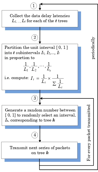
PMT consists of two parts, the latency feedback mechanism and the tree selection scheme. PMT is built upon the following premise: Since each multicast tree does not have the same performance characteristics latency feedback (Lf) can be generated for each multicast tree so that a probability percentage of usage for each multicast tree can be generated. The probability percentage of usage for a given multicast tree is a value indicating how frequently a particular multicast tree may be chosen. For each packet sent, one of the multicast trees is chosen randomly based on its probability percentage of usage. The higher a value for a particular multicast tree, the higher its probability is for being chosen for the next packet to be sent. As a result, the tree with the best performance will be used most often.Lesser performance trees will be used less frequently in order to account for changing bandwidth patterns. The decision to select a multicast tree for a packet about to be sent is based on the generation of a random number and this number is applied against the trees’ probability percentage of usage to make the selection. As the performance of the multicast trees change, the latency feedback mechanism continually provides updated latency values to the source so that the multicast trees’ probability percentage of usage can be recalculated at regular intervals. Figure 4 shows this process.
It is each destination’s responsibility to provide latency feedback so that the source can make an informed decision when choosing the appropriate multicast tree. The latency feedback mechanism is the key to PMT. It is based on transmit time which is used to generate the data delivery latency metric. Each multicast tree is assigned a number. The transmit time-stamp and multicast tree number are included in every packet that is sent by the source. As packets are received by each destination, the transmit time is calculated and summed as part of the data delivery latency. For a given destination, each multicast tree will have a different transmit time. Each destination will compute a latency feedback value for each multicast tree based on the last received packet on that tree.
An exponential moving average is used to generate the latency feedback value where emphasizes recent over older values. It is an averaging calculation that applies an exponential decreasing weight to older data points as new data points are received. The equation Dt= α×dp+ (1–α)×Dt-1where α is the weight, dp is the delay from the current packet, and
Dt and Dt-1arethe new averaged latency value and the last average latency feedback values respectively shows how the moving average was calculated.
Since PMT requires the feedback to be responsive, the weight α chosen was ½ rather than the typical ⅛. The choice of weight value smoothes the immediate changes in the network but the rate of change is still responsive enough to provide timely feedback. Each client provides the calculated latency delay as feedback to its parent. The feedback is sent periodically and must be balanced with network load so that timely feedback is returned but not so quickly that it is disruptive to the network. Even though the feedback value may change with each packet received the value is only sent periodically to prevent burdening the multicast trees with too much maintenance overhead.
The destination sends the feedback latency value to its multicast tree’s parent. Each parent accumulates the latency values from all of its children. Referring to Figure 2 above, each child node sends feedback to the parent node. The parent node collects the latency values, averages them and sends the feedback to its parent node. The process continues until the parent is the root node which sends the feedback latency value to the source. Since each child sends feedback to its parent at regular intervals the parent can determine whether it received feedback from each child or not. It is the parent’s responsibility to supply a latency value for each missing child. Since the child is effectively “out of the network” at this point, the latency value used for each missing child must be sufficiently large compared to the latency feedback of the children that are present so that this multicast tree is penalized compared to other multicast trees. Since the parent can also be a child to another parent its feedback value is the addition of its delay value with an average delay value for all of its children.
Selection of Multicast Trees
Figure 4 describes the multicast tree selection procedure based on the multicast tree feedback latency. The trees are initially generated by Split-stream. All of the feedback delay latencies (Lf) are collected from each of t trees and then divided into t
units over the unit interval (step 1). Each tree’s latency (Li) is normalized into a zero to one interval (Ii). The probability of usage is proportional to its Ii; larger intervals have smaller latencies(step 2). The multicast tree selection uses the multicast tree probability table just described. For each packet that is sent a random number is generated and compared against the intervals (Ii) so that one tree (Ti) is selected for transmission of this packet (steps 3 - 4), refer to Figure 5. Learning occurs when steps 1 and 2 are run periodically based on the needs of the underlying methodology. Steps 3 and 4 are performed for every packet transmitted.
[image:5.595.331.508.79.264.2]Figure 4. Probabilistic Selection Procedure
Figure 5. Tree Interval Selection
Split-stream modifications
To provide the feedback a separate periodic thread was created that executes at a fixed time period. This thread issues feedback data transmission from child to parent in each multicast tree. The feedback packet consists of the accumulated feedback from any children and its average latency delay value. The source node thread was changed to use the probability generation and multicast tree selection algorithm. This thread still sends the same data. Each client node was modified to unload the extra multicast tree information from the packet and record the appropriate metrics. The Scribe [6] “anycast” functionality was added to enable the feedback from child to parent. The clients were modified to discern whether they are a root node or not. A root node has the extra task of sending the feedback to the source since the source is not the parent for the root node’s particular multicast tree.
Results
The FreePastry
[17]
simulator using the GT-ITM [16] delay model was used for testing and modified as described above to run both Split-stream as it was designed and with PMT integrated into it. FreePastry requires 2n number of trees due to its routing algorithm so three different tree counts were used for testing, 4, 8, and 16 trees along with three different node counts of 500, 1000, and 2000 nodeswhich are typical for a Split-stream environment due to the limits of simulator memory.Each test consists of one simulation run which sends 1024 packets into the multiple tree multicast network. In a typical case, the number of packets were never less than 512 or more than 2048.Table 1 shows preliminary results illustrating that the PMT method improves data delivery latency by an average of 25% for smaller node counts due to greater disparity of the feedback values.I
tI
1I
2I
30
1
t
1t
2t
3t
t...
...
Collect the data delay latencies
L1, …, Lt for each of the t trees
Partition the unit interval [ 0, 1 ] into t subintervals I1, I2,..., It
in proportion to
i.e. compute:
t
L
L
L
1
,
,
1
,
1
2 1
i i
i
L L
I
1 1 1
Generate a random number between [ 0, 1] to randomly select an interval,
Ik, corresponding to tree k
Transmit next series of packets on tree k
1
2
3
4
For
ev
er
y
p
a
ck
et
t
ra
n
sm
it
ted
p
er
iod
ic
a
ll
[image:5.595.74.281.312.673.2]Table 1 PMT Total Session Test Results
Number of trees, t
Split-stream data delivery latency,Ld
PMT data delivery latency,Ld
Percent improvement
500, 1000, and 2000 Nodes tests 4 43752 ms 30900 ms 29% 8 39816 ms 30648 ms 23% 16 40059 ms 29455 ms 25%
5000 and 7500 Nodes tests
16 44794 ms 37612 ms 15% 16 41246 ms 37605 ms 8%
For these set of tests, PMT gives a 29% improvement in data delivery latency for a system with 4 trees, a 23% improvement for a system with 8 trees, and a 25% improvement with 16 trees for an average 25% improvement in data delivery latency when compared to Split-stream. Smaller node counts show more improvement with PMT due to disparity of the feedback values which were observed experimentally.This improvement is due to the feedback mechanism and random tree selection, which favors high percentage low latency trees. In multiple tree multicasting, the process of random tree selection allows the occasional selection of high latency feedback trees thereby permitting the reevaluation of the feedback latency in these trees resulting in the ability to detect and learn the changing latency conditions in each tree.
Conclusions
Using the most efficient tree for all transmissions is no different than a single tree multicast with all of its accompanying issues. Multiple tree multicast has an inherent advantage because more nodes participate in the data distribution and multiple trees provide a measure of path diversity. We introduced Probabilistic Multicast Trees which is built into an existing multiple multicast tree protocol. The addition of feedback and random tree selection with PMT reduces data delivery latency. The feedback allows better trees to be used more often which reduces the latency, Ld, and improves efficiency, Ed, at the same time. As tree performance changes and as feedback data is reflected in the probability of usage table implies that PMT learns which trees are better at any given time and that it can make fuller use of them. PMT works best when there is a disparity between the feedback latency of each tree.As node failures cause a negative impact on probability of usage to a given tree, PMT will use this tree less often than other trees. This self adjusting behavior drives the improvement that is delivered by PMT.
In future work we intend to examine feedback frequency and the aggregation of the feedback by the parent nodes. We will investigate integration of PMT at the application level with network layer multicast mechanisms such as IP multicast. We will also examine whether IPv6 has any multicast advantages over IPv4.
Bibliography
[1] Banerjee, S, Lee, S., Bhattacharjee, B. and Srinivasan, A., Resilient multicast using overlays, Proc. of ACM SIGMETRICS, June 2003
[2] Birrer, S. Bustamante, F.E, Magellan: performance-based, cooperative multicast, 10th International Workshop on Web Content Caching and Distribution WCW 2005, Publication Date: 12-13 Sept. 2005, pp: 133- 143
[3] Birrer, Stefan, Bustamante, Fabian E., Resilient peer-to-peer multicast without the cost , Proc. of MMCN, January 2005. [4] Castro, M., Druschel, P., Kermarrec, A.-M., Nandi, A., Rowstron, A. and Singh, A., Splitstream: High-bandwidth multicast in cooperative environments, Proc. of the 19th ACM SOSP, October 2003.
[5] Castro, M., Druschel, P., Kermarrec, A.-M., Rowstron, A., SCRIBE: a large-scale and decentralized application-level multicast infrastructure, IEEE Journal on Selected Areas in Communications, 20 (8) (2002),pp: 1489–1499.
[6] Chu, Yang-hua, Rao, Sanjay G., Seshan, Srinivasan, Zhang, Hui, A case for end system multicast, IEEE Journal on Selected Areas in Communications, Vol 20, Issue 8, Oct 2002
[7] Goyal,V.K. Multiple Description Coding: Compression meets the Network. IEEE Signal Processing Magazine, Sept 2001, Volume 18, Issue 5 pp: 74-93
[8] Johnston, D., McIntyre, D., Wolff, F., Papachristou, C. Optimizing Application Level Multicast Trees over Wireless Networks, IEEE NAECON 2011, July 20 - 22, 2011, Dayton, Ohio
[9] Koutsonikolas, Dimitrios, Hu, Y. Charlie, The case for FEC-based reliable multicast in wireless mesh networks, Proc. of 37th Annual International Conference on Dependable Systems and Networks Washington DC, USA, 2007, pp 491 – 501 [10] Rowstron, Antony, Druschel, Peter, Pastry: Scalable, decentralized object location and routing for large-scale peer to peer systems., Proceedings of the 18th IFIP/ACM International Conference on Distributed Systems Platforms, (Middleware 2001), Heidelberg, Germany, November 2001
[11] Saltzer, J.H., Reed, D.P., and Clark, D.D., End-to-end arguments in system design, M.I.T. Laboratory for Computer Science, ACM Transactions on Computer Systems, Vol 2, Issue 4, Nov 1984, pp 277-288
[12] To, K.K., Lee, Jack Y.B., Parallel overlays for high data-rate multicast data transfer, Computer Networks 51, (2007), pp 31-42
[13] Venkataraman, Vidhyashankar, Yoshida, Kaoru, Francis, Paul, Chunkyspread: Heterogeneous unstructured end system multicast, Proceedings of 14th IEEE International Conference on Network Protocols,November 2006
[14] Yi, Jun, Poellabauer, Christian, Real-time multicast for wireless multihop networks, Journal of Computers and Electrical Engineering Vol. 36, Issue 2, March 2010
[15] Zakhor, Avideh, Wei, Wei, Multiple Tree Video Multicast over Wireless Ad Hoc Networks, Proc. of IEEE International Conference on Image Processing, Oct. 2006, pp 1665 - 1668 [16] Zegura, E.W., Calvert, K.L., Bhattacharjee, S, How to Model and Internetwork, Proc of IEEE INFOCOM, Mar 1996 [17] Free Pastry Simulation
http://www.freepastry.org/FreePastry/