1
Experience in information management and control of electric and magnetic
fields of electrical companies
P. ARNERA
(1), B. BARBIERI
(1), C. WALL
(1), G. MAYER
(1),
O. POSTIGLIONI
(2)J. TURCO
(2)(1)
IITREE-LAT - Facultad de Ingeniería – Universidad Nacional de La Plata
(2)
ENRE - Ente Nacional Regulador de la Electricidad
Argentina
SUMMARY
The use of electricity involves a broad range of activities that cause a wide variety of environmental impacts during the extraction, processing, transport and consuming procedures, due to their diversity, characteristics and relative importance.
It is the role of the State to elaborate the guidelines and regulations for the environmental aspects in the different segments of the market, for different electrical energy sources and in all the stages of the process, from the initial evaluation to the construction and exploitation phases.
On the other hand, the State should exercise the Controller’s role in order to guarantee the adequate environmental management. The State is also faced with the complexity of the negotiations with multiple key players – public, private, national and international- who decide the course of action and the contents of the environmental management.
Among the environmental key aspects to be considerate, there are the electric and magnetic fields, in which society has taken special interest as they are believed to be involved in health hazard.
Some of the faculties of the National Electricity Regulator (Ente Nacional Regulador de la Electricidad - ENRE) include the issuing of regulations and technical procedures to be fulfilled by the agents, and to verify their compliance.
The ENRE has gathered information regarding electric and magnetic fields that includes those planned by the private environmental planning departments and those obtained ex-post in the role of controller. In order to systematize this information, a database has been designed considering different types of electric facilities, the company which they belong to, equipment used in the measurements, representative layouts with measure points and the profiles of electric and magnetic fields that were obtained.
This database results in a management tool for evaluation of the evolution and control of the environmental parameters and in an instrument for communication purposes.
KEYWORDS
Electro Magnetic Fields- Extremely Low Frequency, Measures, Control Management, National legislation, Communication practices.
2
1. Introduction
During the last years the Argentinean “National Regulatory Authority of Electricity” (ENRE: Ente Nacional Regulador de la Electricidad) has been developing a database with the main objective of centralizing all the environmental information collected in relation with electricity. Electric and Magnetic Fields Extremely Low Frequency (EMF-ELF) measurements are available for different kinds of facilities. For these facilities was made a classification, considering power lines, cables, substations and distribution substations.
In order to make this tool useful, the uploading of all historical measurements and the new ones had to be done. This task was carried out by the ENRE, the IITREE (an Institute that belongs to the Engineering School at the National University of La Plata, UNLP) and also the members of the electrical market to be controlled (Agents). Most of these measurements were performed by the IITREE during several years and the complete information included different formats like diskette, CD, sheets of paper only, digital and non-digital photographs, etc.
Among the powers of the ENRE are to dictate regulations and technical procedures to be followed by the agents, to verify the compliance of these regulations and to apply sanctions in the cases of non-compliance. The Environmental Department, as a specific part of the ENRE, plays this role with activities that include performing analysis, answering inquiries and solving complaints. This area also produces reports with technical opinion for the Evaluation of Environmental Impact Studies submitted by those who initiate requests for extending the generation, transmission and distribution system. In order to control EMF levels, the ENRE measures and requires companies to carry out measurements, which are uploaded in the database for monitoring purposes.
The increasing public interest in environmental aspects related to electricity, particularly in EMF, reinforced the effort of the ENRE in not only aspects related to the control role but to those that involve giving information to society in general too. In this way, the database became also a tool to obtain information for communication purposes.
2. National legislation and guidelines
The Secretary of Energy (SE) sets specific protective and environmental control measures of electric activities restricting the emission levels (i.e. emissions of SO2, NOx, PM; limits of EMF, RI, etc). In particular the limit of electric field is 3 kV/m and for the magnetic field the limit is 25 µT, for public areas. [1], [2].
In order to apply the control role, the ENRE published various standards and guidelines:
Res. ENRE 1724/1998, with instructions for measuring electric and magnetic fields in transmission and distribution systems [3].
Res. ENRE 1725/1998, states those agents that must submit an Environmental Impact Study and Management Plan [4].
Res. ENRE 0546/1999: Establishes Environmental Procedures for Construction of Electric 132 kV (or more) Power Transmission [5]
Res. ENRE 555/2001 [6] requires agents to implement “The Environmental Management System”, which establishes the “minimum content of the environmental planning” that the MEM (electrical wholesale market) agents should comply. In this way they have to present a report every semester with the progress obtained in the corresponding issues.
The ENRE has gathered information regarding electric and magnetic fields from both those included in the Companies Environmental Planning and those which were obtained ex-officio in the role of controller.
3
3. Database development.
Regarding the great amount of information related to measurements of electric and magnetic fields generated by electrical public service facilities, it was necessary to create a tool for allowing easy access to such information, with a structure and organization that would enable to compare or to perform specific analysis of the existing records [8].
In order to administrate all the information together in a database, different categories for facilities topologies were defined: substation, distribution substation, aerial line or underground cable. Then inside of these four facilities categories, types and subtypes were also defined according to the voltage level involved, construction characteristics, etc.
Additional information about measurements should be added to complete the data required for each case. This information includes characteristics of the equipment used, atmospheric conditions (temperature, pressure), electric values of measured system like voltage and current, etc.
3.1. Database structure and description of the table information
The “Electromagnetic Fields Measurement Registration and Analysis” is an application which was structured using a commercial relational database. It consists mainly in tables and among them the most important are:
• Measurements
• Power Lines
• Substations
• Distribution Substations. • Underground Cables • Values
Measurements Table: to each registry corresponds an ID number (nº__Medicion). Under this number are also stored general data of the facility (facility type, name, code, address, agent, etc.), the type of measurement performed (electric field, magnetic field), the instruments used and the weather conditions (date, temperature, and atmospheric pressure) and the current values of voltage and current. Since 2010 it includes georeference information of measured facilities.
3.2. Display of the Information
For displaying the stored data, the application shows a window with different sections. It is possible to view some particular facility characteristics, photographs that help users to verify the facility environment, a basic map, and a table of measured values with the corresponding graphic representation, see Figure 1.
[image:3.595.67.526.578.723.2]Another possibility for the user is to search for measurements or select a group that matches with one or several search criteria. This is achieved by the use of filters inside the database.
4
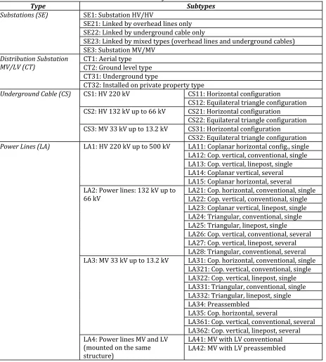
3.3. Facility classification [image:4.595.71.535.183.698.2]It was convenient to classify facilities in four groups and inside each group to define types and subtypes according to their characteristics: Substations (SE); Distribution Substation MV/LV (CT); Underground Cable (CS) and Power lines (LA). The codes for each type and subtypes are shown in Table I.
Table I – Facility classification
Type Subtypes
Substations (SE) SE : Substation (V/(V
SE : Linked by overhead lines only SE : Linked by underground cable only
SE : Linked by mixed types overhead lines and underground cables SE : Substation MV/MV
Distribution Substation MV/LV (CT)
CT : Aerial type CT : Ground level type CT : Underground type
CT : )nstalled on private property type
Underground Cable (CS) CS : (V kV CS : (orizontal configuration
CS : Equilateral triangle configuration
CS : (V kV up to kV CS : (orizontal configuration
CS : Equilateral triangle configuration
CS : MV kV up to . kV CS : (orizontal configuration
CS : Equilateral triangle configuration
Power Lines (LA) LA : (V kV up to kV LA : Coplanar horizontal config., single
LA : Cop. vertical, conventional, single LA : Cop. vertical, linepost, single LA : Coplanar vertical, several LA : Coplanar horizontal, several
LA : Power lines: kV up to
kV LA : Cop. horizontal, conventional, singleLA : Cop. vertical, conventional, single
LA : Coplanar vertical, linepost, single LA : Triangular, conventional, single LA : Triangular, linepost, single LA : Cop. vertical, conventional, several LA : Cop. vertical, linepost, several LA : Triangular, conventional, several
LA : MV kV up to . kV LA : Cop. horizontal, conventional, single
LA : Cop. vertical, conventional, single
LA : Cop. vertical, linepost, single
LA : Triangular, conventional, single
LA : Triangular, linepost, single
LA : Preassembled
LA : Cop. horizontal, several
LA : Cop. vertical, conventional, several
LA : Cop. vertical, linepost, several
LA : Power lines MV and LV mounted on the same structure
5
4. Use of database for communication practices.Part of the information obtained from the database is transferred using the ENRE website (http://www.enre.gov.ar/), other institutions (by information interchange) and direct speech to the public.
4.1 Website
The Environmental Area of the ENRE can share different kind of information related to environmental topics, such as those related to “transmission and distribution facilities”, “levels of EMF-ELF measured and computed”, “health effects” and “standards”.
It is possible to see the classification described in Table I with photographs that identify each type of facility.
4.1.1 General information about EMF
Here it is possible to find general information about EMF-ELF; natural and artificial sources of electric and magnetic fields, and basic information for people who are not related to these topics.
4.1.2 Transmission and distribution facilities
Here it is possible to find the main features of the various electrical systems used in Argentina and also provides a description of the structure of the EMF database, like the description given in 3.
4.1.3 Health Effects
In this section it is possible to find links with web pages that include information with relation to this topic. For example it is possible to reach the sites of:
National Institute of Environmental Health Sciences/National Institutes of Health International Commission on Non-Ionizing Radiation Protection (ICNIRP) The International Agency for Research on Cancer (IARC)
World Health Organization (WHO) 4.1.4 Standards
In the standards area it is possible to see resolutions and guidelines about environmental aspects published by the ENRE. These standards were given in part 2 of the text.
4.1.5 EMF-ELF levels
In this group it is possible to see reports with information collected from the database, where different facilities are displayed with photographs, layouts and profiles.
For general public it is important to access to this information in this easy way. It is possible to obtain a clear dimension of the magnitude of EMF-ELF levels, and users could easily extrapolate those values to other similar facilities and to compare them. The values are not probably the same, but it is possible to obtain an idea of them.
It is clear that for further information in particular cases, it is convenient to consult specialists or to ask directly to the ENRE.
The following examples will try to illustrate some real measurements and simulations that can be found in the ENRE website.
As a first example, simulations and measurements of electric and magnetic field profiles are presented. These cases belong to power lines of 500kV and 132kV.
6
Figure 2: Power Line 500 kV(LA11)
-50 -40 -30 -20 -10 0 10 20 30 40 50
0 1 2 3 4 5 6
Distance from line centre [m]]
B [
T]
Comparison between measured and calculated values
Calculated Measured
Figure 3: Magnetic field, Power Line 500 kV (LA11)
-50 -40 -30 -20 -10 0 10 20 30 40 50
0 1 2 3 4 5 6
E [
k
V/
m
]
Distance from line centre [m] Comparison between measured and calculated values 500 kV
Calculated Measured
Figure 4: Electric field, Power Line 500 kV (LA11)
[image:6.595.83.517.257.398.2]Typology, results of simulation and measurements records of electric and magnetic field for a line at 132 kV, are presented in Fig. 5, Fig. 6 and Fig. 7.
Figure 5: Power Line 132 kV (LA24)
-50 -40 -30 -20 -10 0 10 20 30 40 50
0 0.2 0.4 0.6 0.8 1
Distance from line centre [m]
B [
T]
Comparison between measured and calculated values 132 kV
Calculated Measured
Figure 6: Magnetic field, Power Line 132 kV (LA24)
-40 -30 -20 -10 0 10 20 30 40
0 0.05 0.1 0.15 0.2 0.25 0.3 0.35 0.4 0.45
E [
k
V/
m
]
Distance from line centre [m] Comparison between measured and calculated values 132 kV
Calculated Measured
Figure 7: Electric field, Power Line 132 kV (LA24)
[image:6.595.78.287.456.611.2]An example of measurements in substations is shown in Fig. 8, 9, 10 and 11. It is possible to see an schematic plot of the substation surrounded by the measured points. These measured values appear also in the set of figures.
[image:6.595.324.510.460.605.2]7
5 10 15 20 25 30 35
0 5 10 15 20 25 Measurement Points B [ T]
[image:7.595.85.499.73.251.2]Magnetic Fields Levels - Substation
Figure 10: Magnetic Field levels around a Sub-Station (SE23)
5 10 15 20 25 30 35
0 0.05 0.1 0.15 0.2 0.25 0.3 0.35 0.4 0.45 0.5 Measurement Points E [ k V/ m ]
[image:7.595.314.500.75.222.2]Electric Fields Levels - Substation
Figure 11: Electric Field levels around a Sub-Station (SE23)
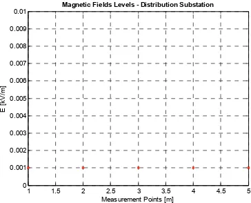
[image:7.595.78.513.300.698.2]An example of measurements in a Distribution Substation is shown in Fig. 12, 13, 14 and 15. It is possible to see a schematic plot of the substation surrounded by the measured points. These measured values appear also in the set of figures.
Figure 12: Measurement in a Distribution Substation (CT32)
CONDE STREET References:
A) Chamber access cover. B) Cover for lifting the transformer. C) Ventilation windows. D) General access door from sidewalk. E) Building line.
CT 77010 D E School Schoolyard School 3,50m 6 ,4 6 m A B C C
1 2 3 4 5
Profile 1 Profile 2 Profile 3
Measurements grid
Figure 13: Measurement Points around a Distribution Substation (CT32)
1 1.5 2 2.5 3 3.5 4 4.5 5
0.2 0.4 0.6 0.8 1 1.2 1.4 1.6 Measurement Points B [ T]
Magnetic Fields Levels - Distribution Substation
Profile 1 Profile 2 Profile 3
Figure 14: Magnetic Field levels around a
Distribution Substation (CT32)
1 1.5 2 2.5 3 3.5 4 4.5 5
0 0.001 0.002 0.003 0.004 0.005 0.006 0.007 0.008 0.009 0.01
Measurement Points [m]
E [
k
V/
m
]
Magnetic Fields Levels - Distribution Substation
Figure 15: Electric Field levels around a Distribution Substation (CT32)
4.2 Information interchange
[image:7.595.313.507.309.483.2] [image:7.595.76.288.311.464.2] [image:7.595.317.499.509.656.2]8
4.3 Direct speech to the publicAdditionally, in some cases a face to face contact with the community is necessary. In these cases the ENRE requires the assistance of EMF experts from Universities to give additional and competent information in topics like health and physics. This activity is not an easy one and requires teaching skills. In this way IITREE professionals take part in this task.
People in general are thankful when they receive further and serious information.
5. Final Comments
In order to centralize information and to improve the access to it, a database for electric and magnetic field measurements was developed. This also speeds up the process of finding solutions to people complaints and maintaining a continuous control in all public areas.
Up to the moment, the database has been loaded with a total of 3381 registries; 1690 of them correspond to electric field measurements and the other 1691 to magnetic field.
563 correspond to Substations. 1962 Power Lines.
793 Distribution Centres. 63 Underground Cables.
This database allows continuous upgrading with new registries from future measurements. Different searching options are also admitted by the database.
The increasing amount of data permits improving communication between society and authority using updated information, especially in the case of sensible areas like schools, hospitals, nurseries, etc. This is very important considering that false information comes very fast to the general public. In this way, it is remarkable the educational role played by the ENRE and the IITREE together in order to facilitate knowledge acquisition by people. This task is also enhanced by the use of direct contact with people in those social-sensible cases.
It is also important to remark that the maximum levels admitted in Argentina for EMF (3 kV/m and 25 µT) are below those internationally recommended, for example ICNIRP (5 kV/m and 200 µT) [9]. However in some areas people worries and complain even in those cases that are below the mentioned levels.
With this new systematised tool it is possible to know more details about different constructive types and to evaluate their performance.
Another important contribution of this data collection is the help given for the development of computational models for predicting electric and magnetic fields.
It is interesting to observe how a control tool can be used as a very important instrument for assistance in communication practices.
BIBLIOGRAPHY
[1] Resolución SE 77/1998. Boletín Oficial N° 28.859, miércoles 18 de marzo de 1998. [2] Resolución SE 1794/1998. Boletín Oficial N° 29.038, lunes 7 de diciembre de 1998.
[3] Resolución ENRE 1724/1998. Boletín Oficial n° 29.038, lunes 7 de diciembre de 1998, pp. 25-26.
[4] Resolución ENRE 1725/1998. Boletín Oficial n° 29.038, lunes 7 de diciembre de 1998,
p. 26
[5] Resolución ENRE 0546/1999. Boletín Oficial n° 29.135, miércoles 28 de abril de 1999,
p. 17.
[6] Resolución ENRE 0555/2001. Boletín Oficial n° 29.759, miércoles 24 de octubre de 2001. [7] Res ASPA N° 01/2010 - Guía de Contenidos, Formatos y Presentación de los Informes previstos
en la Resolución ENRE N° 555/2001. (no publicada en B.O.) , miércoles 8 de septiembre de 2010, 3 p.
[8] “Management Tool for control of electric and magnetic fields of electrical companies”. P. Arnera, B. Barbieri, J. Turco, J. Messina, O. Postiglioni. 12th International Congress of International Radiation Protection Association, Buenos Aires, Argentina, 19/24 October 2008. [9] “Guidelines for Limiting Exposure to Time-Varying Electric and Magnetic Fields (1 Hz to 100