DATA BASES AND DISCRETE EVENT SIMULATION
Abdelhak Boubetra
1, Hocine Belouadah
1, Nassreddine Mouhoub
1 Department of computer scienceUniversity of Bordj Bou Arreridj EL ANNASSER 34000
ALGERIA [email protected]
ABSTRACT
This paper is an attempt to define how a
specific data structure might be used to
store, in a persistent manner, temporal
information during a computer simulation.
In particular, it considers the sort of
temporal information generated during a
discrete event simulation of a system to
which a relational data base exists and
considers the demands this data makes on
data base design.
Key-Words: -
Computerized system,
temporal data, discrete event simulation,
data base
1. Introduction
Simulation is the act of experimenting with a model representing a system. It serves as direct means of observing the system’s behavior within time and starting from a chosen initial state. If the system to be simulated is computerized (a data base for the system under investigation exists) the simulation writer can gain in the initialization phase of the simulation by starting his simulation runs from existing data by connecting the output of the query system of the existing data base management system (DBMS) to the simulation system.
In addition, there are requirements to find ways and means for the case where the simulation writer is asked by the data base user to write back the simulation results into the user database since he is accustomed to interrogate his computerized system with his own DBMS. Here difficulties can arise due to the fact that most of existing DBMS were not conceived to support temporal data with which simulation deals.
Thus, a simulation temporal data structure to store the dynamic data and their relationships, which are of primary interest to the discrete
simulation modeler, is wanted and needed. In other words, the aim of our suggestion is to investigate the simulation of computerized systems and to provide a design approach to a data structure for simulation which can be implemented with simulation systems and interfaced with an existing data base of the system under simulation.
In this paper we are concerned with how to deal with the generated behavior in simulation in the context of a computerized system. To tackle that, we first introduce a description of the concepts in which discrete event simulation has grown and highlight the recent recommendations for the simulation on which our suggestion was conducted. In a second phase, we point out the possibility of building a simulation temporal data structure that can be interfaced to an existing data base and helps understanding the behavior of a wide range of systems.
2. Simulation and DBMS
serious discussion about the usage of relational or object-oriented databases and for his implementation he choose a relational database. The attributes of the database-tables are of two groups: a set of attributes for administration and others for the storage of the objects data. This data structure was used for all model entities and a relational language called SimSQL was introduced for manipulating the model during design and run-time. From another point of view, an article (Henk de Swaan Arons 1999) investigated the use of a database of existing models can help and save time to select a model that in some sense is close to the system under study. On the other hand from a simulation data collection point of view, N.H. Roberstson and T. Perera (2001) argued that automating this phase by interfacing the corporate business systems as a potential data source for simulation will accelerate the data collection process needed to run the simulation. A previous research (L.G. Randel and G.S. Bolmsjo 2001) developed a modular software designed to reduce the modeling and maintenance effort when modeling an entire factory where the database used to automatically generate and drive the simulation model is a copy of the production planning database. Here, it has been shown that it is easy to integrate a simulation system with other computer systems (a database).
3. Simulation requirements and
temporal aspects
As a summary of the above suggestions,
we notice that the database modeling
techniques concentrate almost exclusively
on static views of the system being
modeled. However, simulation
concentrates on dynamic views of the
system being modeled. What is modeled
is the system behavior or the dynamism of
the real world. Thus, the need to have
something in the database that represents a
system entity (object) behavior just as a
collection of events drives an entity
through its behavior in the real world. To
do so, in specifying the dynamic behavior
of a system, time forms the core of any
simulation study. It appears that temporal
databases that capture what is known
about events and their effects occurring
over time can meet the requirement of a
database for the simulation. T.Mclean,
L.Mark, M.Loper and D. Rosenbaul
(1998) put important questions regarding
the utility and viability of a temporal
database for simulation. They were
seeking issues of how and where to collect
the data in a simulation and noted the
opportunity to explore temporal database
concepts to embody simulation
requirements. In our view, we confirm
that it is difficult to keep track of all the
execution of large simulation studies in a
simulation program. A well-integrated
temporal data structure is the issue in this
problem in order to provide facilities for
organization, access and control of the
data.
4. Approach to the simulation temporal
data structure
even implemented without performance and storage problems and we show how we can keep track of a number of situations occurring at different times and we can move from one snapshot to another backwards and forwards in order to learn what was produced at that snapshot and what has led to this situation.
Fig 1: A cubic view of the system changes
With the cubic representation applied to the simulation; each horizontal slice will indicate the changes at a specific snapshot of a simulation object. The upper horizontal slice represents in general the most current view of the simulated system object. However, this representation reveals some difficulties. When some attributes of an object remain unchanged but others change their states at a snapshot, the
object
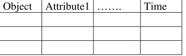
can be assumed to have logically taken the last state at the most current snapshot which is not true.Because much work has been done in processing tables without time support, we can see that the three dimensional structure can be converted into a two dimensional table by adding a time attribute like in figure 2.
Object Attribute1 ……. Time
F
ig 2: Relational table with time support
It is obvious that figure 2 can be implemented directly on any relational database systems. The additional attribute Time, can be used to store the simulation time values for each tuple. When a tuple is created, the time value at that snapshot will be stored. It is clear that it is not sufficient to have only one attribute for time. While it is adequate to support creation and update but it is not adequate to
support deletion because we only store the last state of an entity. A more realistic data structure model would be a 3-dimensional structure where the first dimension represents the entities, the second one represents only the changes of the attributes and the third is the time dimension as in figure 3. The simulation temporal will be based on this approach.
Objects
Time
Attributes
Fig 3: Irregular cubic view of the data
5. The simulation temporal data
structure design
In discrete event modeling , entities may be divided into classes. Each class is composed of entities having the same attributes and characteristics. To perform the cubic representation of figure 3, we extend our concept to include the history behavior of the simulated system. Instead of building one table for each class of entities with additional time attributes to contain all the tuples and their changes since their creation, we shall have a table that contains only the current tuples as is done in the current view systems. However, to capture the time aspect we will have its value stored with the tuples of the current view. This time will not behave as in the case where the temporal domain is supported by adding the time attributes to the tables.
Included with each tuple will be a pointer that points to the first history tuple when there is as shown in figure 4.
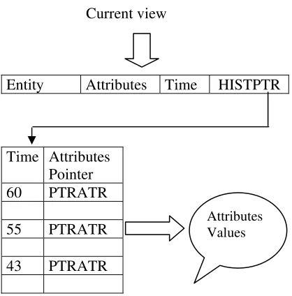
[image:3.595.83.288.175.304.2] [image:3.595.319.526.193.341.2] [image:3.595.85.273.553.610.2]entities. Now we go into discussion of our approach and focus on the performance and the design of the historical view which is illustrated in figure 5. We organize another table for sequential accessing of the time aspect which will be referred to as the simulation historical table and it consists of two fields. The first one represents the time and the second one is a pointer to the attributes values of an entity. In this figure, the historical pointer HISTPTR of the entities class points to the simulation historical table which acts as a pointer to the attributes values of the entities with the time as a key access in the first field. The second field of the simulation historical table is a pointer to the attributes which have undergone a change. This pointer is denoted in figure 5 by PTRATR.
Entity 1
V(attr1) V(attr2) V(time) HISTPT R
Entity n
V(attr1) V(attr2) V(time) HISTPT R
Histotical View Of entity n Historical view
of entity 1 ..…
[image:4.595.84.293.526.738.2]�
Fig 4. Current and historical view of an entities class
Current view
Entity Attributes Time HISTPTR
Time Attributes Pointer 60 PTRATR
55 PTRATR
43 PTRATR
Fig 5. Simulation historical table
In discrete simulation modeling, at a snapshot the changes on the attributes are arbitrary, that means one or more attributes of an entity undergo a change. As we are interested in the historical view to keep only the changes of some of the attributes so we must take care of this condition. In fact, the pointer PTRATR of the simulation historical table points to another table showing the attributes of the entity of interest which have undergone a change at a specified snapshot. This table is composed of three fields: the first field represents the table identity holding the attribute values, the second one is the record number in the attribute values table and the third field is a pointer to the next attribute of the same entity having undergone a change at this specified snapshot. Figure 6 is an illustration of the data structure. For example the entity: ENTITY undergoes a change at the snapshot 60 which concern only the attributes: atr1, atr2 and atr3 which their values are in the records 30, 45 and 50 of the table TABLE1, TABLE2 and TABLE3 respectively.
6. Conclusion
This paper has suggested the use of a temporal data structure to meet the need for supporting the data outcome of a simulation running. This structure represents an efficient framework to reason about simulation and time since its design is based on a three dimensional view (entity, attributes, time). Thus the simulation temporal data structure is a kind of irregular cube of the simulation data where each horizontal slice represents only the changes of a specific snapshot of the simulation. Beside that, there is much benefit in the ability of moving backward and forward within the simulation temporal data structure and slicing it into snapshot states which may in the future form a means to write back the simulation results or each snapshot state into an existing data base of the system to be simulated. This ability provides Managers, when taking decisions, with a means to move backward and forward within the time to see the evolution of the simulated system at a specified time.
7. References
[1] Arons H. S. 1999. Knowledge-based modeling of discrete-event simulation
systems. In proceedings of the 1999 winter
simulation conference, ed. P.A. Farrington, H.B. Nembhard, D. T Sturrock, and G. W. Evans, 591-597 : society of computer simulation.
[2] McLean T., Mark L., Loper M. and rosenbaum D. 1998. Applying temporal databases to HLA data collection and
analysis. In proccedings of the 1998 winter
simulation conference, ed. D.J. Medeiros, E.F. Watson, J.S Carson and M.S. Mannivannan, 827-833 :society for computer simulation.
[3] Randell L.G. and Bolmsj G.S. 2001. Database driven factory simulation : a
proof-of- Concept demonstrator. In proceedings of
the 2001 winter simulation, ed.B.A. Peters, J.S. Smith, D.J Medeiros and M.W.Rohrer,
977-983: Society for computer simulation.
[4] Robertson N.H. and Perera T. 2001. Feasibility for automatic data collection. . In proceedings of the 2001 winter simulation
conference, ed. B.A. Peters, J.S. Smith,
D.J.Medeiros and M.W. Rohrer, 984-990 :Society for computer simulation.
[5] Standridge C. R. and Wortman D.B. 1981. The simulation data language (SDL), a Database management systems for modelers,
Simulation journal; August 1981: 55-88.
[6] Standridge C.R. 1999. Modular simulation environments. An object manager based
architecture. In proceedings of the 1999
winter simulation conference, ed.P.A. Farrington, H.B. Nembhard, D.T. Sturrock, and G.W. Evans,598-602 : Society of computer simulation.
[7] Wiedmann T. 1999. Database oriented
modeling with simulation microfunctions. In
proceedings of the 1999 winter simulation conference, ed. P.A. Farrington, H. B. Nembhard, D.T. Sturrock, and G.W. Evans,
586-590: Society of computer simulation.