adcarnie@lac.inpe.br
Applied Computing Program, National Institute for Space Research, Av. dos Astronautas, 1758 – Jardim da Granja
São José dos Campos, SP, 12227-010, Brazil
Mario Jino
jino@dca.fee.unicamp.br
School of Electrical and Computer Engineering, State University of Campinas Av. Albert Einstein – 400 – Barão Geraldo
Campinas, SP, 13083-970, Brazil
Marcos Lordello Chaim
chaim@usp.br
School of Arts, Sciences and Humanities, University of São Paulo, Av. Arlindo Bétio, 1000 – Emerlino Matarazzo
São Paulo, SP, 03828-080, Brazil
ABSTRACT
Understanding how a user interacts with a system is important if the goal is to deliver a product that meets the user's needs. Use cases constitute a primary source of requirements in a user-centered perspective and are often utilized to derive acceptance tests. Given such a critical role in requirements engineering, we introduce a novel set of testing criteria based on the use case specification with a two-fold objective: to assess the quality of test cases derived from use cases and to test the use case specification itself. Differently from previous approaches, the novel set of testing criteria requires that structural elements of the use cases be exercised at least once. To support the application of the new set of testing criteria, a testing coverage tool, called UCT -Use Case Tester, was developed. A case study using UCT shows that the new testing criteria are able to evaluate the quality of a test data set as well as to detect faults in use case specifications.
Keywords:structural testing, use case, software testing, UML
1. INTRODUCTION
The increasing need for reliable software products makes the software testing activity pivotal to the software process. This activity consists of defining the relevant aspects of the software, namedtest requirements, which should be checked by test cases. Depending on the source of information used to obtain the test requirements, the testing carried out is classified as based on specification (functional testing) or based on code (structural testing) [1].
Regarding program testing, there is a growing body of evidence showing that structural and functional testing and reading techniques are complementary since they reveal distinct classes of defects [2]. On the other hand, the same situation is not observed in the testing of pre-code representations; mainly because pre-code representations are regarded as a source of functional test requirements, especially acceptance tests. However, pre-code representations have a well-defined structure too, and
this structure may be used as a source for identifying test requirements.
One of the possible benefits of applying structural testing on pre-code representations is to reveal defects that would not be detected if only functional tests were applied. The hypothesis is that the behavior observed in program testing is mimicked in pre-code testing. We explore this idea in testing use case specifications [3].
Use cases are being widely used to determine the functional requirements of a system. A use case may be defined as a sequence of actions a system executes to yield an observable result of value to its actors [4]. In the Unified Modeling Language (UML), the use cases are graphically represented in a diagram, which also shows the relationships among them. These relationships determine the diagram structure.
Many test techniques utilize use cases as a source of information for deriving test requirements [5, 6, 7, 8]. Nevertheless, these techniques utilize use cases to identify functional test requirements and disregard the testing of structural aspects of this specification. To fill in this gap, we propose testing criteria which aim at exercising the internal structure (relationships) of the use case diagram.
The reason for applying the new set of criteria is to assure the testing of the minimal but essential elements of this diagram. We hope by testing the structure of the use cases to detect classes of defects distinct from the ones identified by the use case functional testing. In doing so, we aim at accomplishing a two-fold objective: to assess the quality of functional test cases derived from use cases; and to test the use case specification itself.
whether the use case structural testing can indeed detect distinct classes of defects.
The remainder of this paper is organized as follows. In Section 2, the use case structure is presented. Section 3 contains the definition of the proposed testing criteria. The UCT test coverage tool is described in Section 4. Section 5 contains a case study of the new criteria application; and Section 6, a discussion concerning the related work. Finally, in Section 7, we draw our conclusions.
2. USE CASE DIAGRAM STRUCTURE
In what follows we review the concepts that define the use case structure and introduce other ones used to establish the proposed criteria.
Use case diagram elements
The use case diagram, in the UML context [9], is used to model the functional aspects of a system. It consists of
actors, use cases andrelationships. Relationships relate
actors to actors, actors to use cases and use cases to use cases establishing the use case diagram structure. These three elements are shown in Figure 1.
Supply Customer
[image:2.595.93.284.423.636.2]Data
Figure 1. A use case diagram extracted from the UML Specification v1.5, pp.3-99 [4].
Anactor, indicated in the diagram by a stick man,
represents the role of a user or an external system interacting with the system being modeled. Use cases, represented by ellipses, define a sequence of actions a system executes to yield anobservable resultof value to its actors [4].
Relationships between actors and use cases establish the participation of actors in use cases. An actor may be related to another actor by a relationship of generalization. Use cases can relate to other use cases through three types of relationships – include, extend and generalization. A use case may be invoked by another use case as well as by a message from an actor.
Use case relationships
For the description below, the basic use case in a relationship between two use cases is the one which has its behavior augmented by the behavior of the other use case.
Association relationship. Interaction represented
by a solid line between an actor and a use case. It indicates which actors communicate with each use case of the diagram. For instance, in Figure 1 actorSalespersonhas an association relationship with use casePlace Order.
Includerelationship. Interaction represented by a
dashed arrow labeled with the keyword <<include>>. An include relationship from use case A to use case B indicates that use case A contains the behavior specified in B. An include relationship has in general a static connotation. The instance of an included use case will always be performed unless the include relationship is located in an alternative flow of the basic use case (an alternative flow deals with exceptions and strange cases [7]). The behavior of the included use case is part of the behavior of the basic use case. For instance, in Figure 1 use casePlace Orderincludes the behavior of use cases
Supply Customer Data, Order Product and Arrange
Payment.
Extend relationship. Interaction represented by a
dashed arrow labeled with the keyword <<extend>>. An extend relationship from use case C to use case D indicates that use case D may be augmented (subject to specific conditions specified in the extension) by some behavior specified in C. The basic use case D may also be augmented by part of the behavior of C. Moreover, the basic use case should not depend upon the addition of the extending use case C to carry out its behavior. The extend relationship has a dynamic connotation; it will take place only if the relationship condition is satisfied. For instance, in Figure 1 use case Request Catalog may extend the behavior of use casePlace Orderif additional requests are wanted.
Generalization relationship. A generalization from
an actor A to an actor B indicates that actor A can communicate with the same kinds of use cases as actor B. A generalization relationship from use case E, named child use case, to use case F, named parent use case, indicates that E is a specialization of F. In both cases, this relationship is represented by a generalization arrow; i.e., a solid line with a closed, hollow arrow head pointing to the parent actor or use case [4].
Order Product
Arrange Payment
Place Order Extension points Additional requests: After creation of the order <<include>>
Request Catalog <<include> <<include>>
<<extend>> the salesperson
for asks the catalog
1
*
Exercising Use Case Relationships
Our testing criteria require that use case relationships be exercised by test cases. In what follows, we define precisely what is meant by exercising use case relationships.
Exercising an association relationship. An association relationship between an actor and a use case is exercised by a test case that makes the actor to require the behavior of the use case.
Exercising an include/extend relationship. An include/extend relationship between use cases A and B is exercised by a test case that makes use case A to include/extend the behavior of use case B.
Exercising a generalization relationship. This relationship is exercised by exercising the relationships associated to the specializations.
3. USE CASE STRUCTURAL TESTING CRITERIA
We have defined a family of testing criteria which aims at exercising particular elements of the use case diagram [10]. The elements considered in the criteria are: association, include and extend relationships. We say a test setsatisfiesa criterion when all of its test requirements are exercised by the elements of the test set.
The criteria are defined according to which relationships should be exercised and in the way they are exercised. We define two classes of criteria, namely, based on relationships and based on the combination of the extend relationships. Due to space restrictions, we present only one criterion of each class.
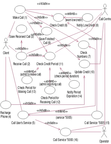
Figure 2 contains a use case diagram used to illustrate the test requirements defined by these criteria. This diagram was obtained from the user's manual of a prepaid mobile phone system [11]. It represents a system for monitoring and billing cell phone calls (for simplicity, we refer to it as billing system).
Testing criteria based on relationships
The criteria based on relationships require exercising the relationships in the use case diagram. The criterion presented below requires exercising all the relationships in the diagram and is defined as follows.
All-Associations-Inclusions-ExtensionsCriterion (c1).
Given a test setTand a use case diagramD,Tmust cause each association, include and extend relationship inDto be exercised at least once.
One can observe that this criterion assures the full coverage of all types of relationships considered during the test based on use cases.
Notify Low Credit (8)
Call Service *5005 (15) Check
Numbers (7) Check Credit (6)
(warn low credit) <<extend>>
<<include>> Save Received Call (3)
Client
Save Finished Call (9)
Recharge Phone (4)
Operator Call User's Service (5)
<<include>>
(service *5005) <<extend>>
Update Credit (10) <<include>>
<<include>>
Call Service *5000 (16) <<include>>
Make Call (1) <<include>>
<<include>> <<include>>
Receive Call (2) <<include>>
Check Period for Making Call (13)
Check Period for Receiving Call (12)
Notify Period Expiration (14)
Call Centre
Check Credit Period (11) <<include>>
<<include>>
(admit to make call)<<extend>>
[image:3.595.324.510.221.463.2](admit incoming call)<<extend>> (check period duration)<<extend>>
Figure 2. Use case diagram of a system for monitoring and billing cell phone calls (billing system). The number at the
end of each use case's name is its identifier. The application of criterion c1 on the billing system requires exercising a set of relationships. These relationships are represented below by pairs of identifiers. In the association relationship, the first identifier refers to the actor. In the include and extend relationships, the identifier that represents the basic use case in each relationship is the first and the second one, respectively. The order of a pair of identifiers obey the direction of the include or extend relationship arrow.
According to criterion c1, the relationships that should be exercised on the billing system are the following:
- Association: client-use case 1; client-use case 2; client-use case 4; client-use case 5; call centre-use case 1; call use case 2; call use case 11; call centre-use case 10; call centre-centre-use case 16; operator-centre-use case 16
- Include: 1-6; 1-7; 1-9; 1-11; 2-3; 2-11; 4-10; 5-7; 5-16; 9-10; 15-6
Testing criteria based on the combination of the extend relationships
The extend relationship is related to a condition that must be satisfied if the extension is to take place [4]. Based on the fact that the condition value decides whether an extension will take place or not, we have proposed criteria that require not only exercising extensions but also non-exercising them [10]. Consequently, these criteria define test sets which exercise the combination of exercising and non-exercising the extend relationships. We formally describe one of these criteria – the
all-extended-combinations criterion.
All-extended-combinations Criterion(c2). Given a test setTand a use case diagramD, for each use case inD
[image:4.595.98.280.374.570.2]extended by at least two other use cases,Tmust cause all the combinations of exercising and non-exercising the extend relationships to be exercised at least once.
Table 1. Criterionc2test requirements. Extensions Test
Requirement 12-11
13-11
14-11
exercised
r1 E E E X
r2 E E NE X
r3 E NE E ¥
r4 E NE NE ¥
r5 NE E E ¥
r6 NE E NE ¥
r7 NE NE E X
r8 NE NE NE X
Table 1 shows the test requirements of criterionc2
for the billing system use case diagram, which presents the use case 11 being extended by three other use cases, namely, use cases 12, 13 and 14. In the first row of Table 1, the test requirement r1 means that the extend relationships12-11,13-11and14-11should be exercised. The test requirements fromr2 to r8represent the other combinations of exercising and non-exercising of the same extend relationships, totalizing eight (23) combinations. In each test requirement, an abbreviationEindicates that the extend relationship should be exercised andNEindicates it should not.
4. UCT TESTING TOOL
A testing coverage tool called UCT –Use Case Tester– was developed to support the application of the new
testing criteria. This tool has three main functionalities: determination of test requirements (according to selected criteria); simulation of test case execution on descriptive specifications of use cases; and coverage analysis of simulated test cases. These three functionalities are described below.
Determination of test requirements
In UML the use cases are graphically represented in the use case diagram; however, the use case diagram does not suffice to describe the use case behavior. As a result, textual specifications have been utilized to complement the use case diagram [12]. These specifications use informal textual notation which is adequate to describe use cases but do not favor their automated analysis.
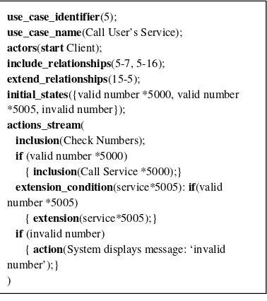
[image:4.595.315.504.409.622.2]Thus, there is a need for a formal notation to generate use case descriptions. We have defined a notation that is utilized by UCT for use case description with this purpose. This notation is based on Cockburn's framework [12] and is presented in [10]. Figure 3 contains the description of use caseCall User's Serviceusing the UCT notation. The notation reserved words are in bold.
Figure 3. Example of the UCT notation for use case description.
From the static analysis of the files that describe the use cases of a system, UCT maps each use case to an internal representation composed of two other lists: one that contains the inclusions among the current use case and the other use cases and the other that contains the extensions. These lists are traversed to determine the test requirements of the criteria chosen by the tester.
use_case_identifier(5);
use_case_name(Call User’s Service); actors(startClient);
include_relationships(5-7, 5-16); extend_relationships(15-5);
initial_states({valid number *5000, valid number *5005, invalid number});
actions_stream(
inclusion(Check Numbers); if(valid number *5000)
{inclusion(Call Service *5000);} extension_condition(service*5005):if(valid number *5005)
{extension(service*5005);} if(invalid number)
{action(System displays message: ‘invalid number’);}
Simulation of Test Case Execution
In addition to the lists of inclusions and extensions, the internal representation of a use case contains a graph representing the use case stream of actions. This graph is generated from the use case textual representation and is used to simulate its behavior.
The simulation of a use case behavior consists of, given a set of initial states (the test case input data), walking through the use case graph of actions to determine which inclusions and extensions are exercised. Thus, it identifies the test requirements exercised for a specific test set and allows checking the use case behavior by analyzing the simulated sequence of actions.
During simulation, when a use case includes another one the UCT tool requests the user to select a set of initial states related to the included use case. When a use case being simulated encounters an extension point in its flow of actions, the extension will occur or not occur according to the set of initial states selected for this use case simulation. If the extension occurs, the UCT tool requests the user to select a set of initial states related to the extending use case. Below we present the sumary of the simulation of a test case execution regarding use case make call.
SIMULATION SUMMARY
Use case 1 simulation
---Test data for use case 1: makeCall, or-dinaryNumber, validNumber,
sufficientCredit,validCreditPeriod
Include relationship exercised: 1-7
Test data for use case 7:
ordinaryNumber,realNumber,areaNumber
Include relationship exercised: 1-6
Test data for use case 6: creditAmount
Extend relationship exercised: 8-6
Test data for use case 8:
-Include relationship exercised: 1-11
Test data for use case 11: makeCall,equalSystemDate
Extend relationship exercised: 12-11
Test data for use case 12:
-Extend relationship exercised: 13-11
Test data for use case 13: firstPeriod,ordinaryNumber
Extend relationship exercised: 14-11
Test data for use case 14: expiringCurrentPeriod
Include relationship exercised: 1-9
Test data for use case 9: normalEndCall
Include relationship exercised: 9-10
Test data for use case 10: makeCall
---Coverage Analysis
Once the sequence of inclusions and extensions exercised during the use case simulation has been generated, this sequence is compared with the test requirements of the applied criteria. The result is the coverage of the criteria with respect to the test cases for which the execution was simulated. Note that the test requirements were previously generated and were stored into internal structures of the tool. Below the coverage analysis of the test case execution regarding use casemake callis presented.
COVERAGE ANALYSIS OF CRITERION All-Extended-Combinations
--- Testing requirements exercised during simulation
---Combinations of relationships
12-11 13-11 14-11
E NE E
E NE NE
NE E E
NE E NE
---- Testing requirements not exercised during simulation
----Combinations of relationships
12-11 13-11 14-11
E E E
E E NE
NE NE E
NE NE NE
---5. CASE STUDY
Case study description
Heumann's approach was applied to derive the functional tests [7]. This approach consists of identifying a set of scenarios for each use case and developing one or more test cases for each scenario. The functional tests were simulated and evaluated using UCT to assess their adequacy (coverage) with respect to the new criteria.
Results and Discussion
The functional tests satisfied all criteria based on relationships. Regarding the criteria based on the combination of the extend relationships,
all-extended-combinations criterion(c2) was the only one not satisfied
by the tests. Table 1 indicates the test requirements of criterionc2 not exercised (symbol X in the last column) and exercised (symbol¥in the last column) during the simulation.
Two non-exercised test requirementsr1andr2are
infeasible; i.e., there are no input data that causes these
test requirements to be exercised. For these requirements the conditions of the extend relationships 12-11 and 13-11 are mutually exclusive (12-11 –admit incoming call;
13-11 –admit to make call).
The other two non-exercised test requirements, r7 and r8, reveal the existence of two scenarios not executed by the functional tests. The first scenario, represented by the requirement r7, consists of exercising use cases 11 and 14 (use cases Check Credit Period and Notify Period Expiration, respectively) without exercising use cases 12 and 13. This scenario is executed when the Call Centre, in every automatic change of system data, asks for checking the validity of the client's credits in the context of prepaid cell phones. The aim is to send a message warning the customer that her credits are expiring within three days.
The second scenario, represented by the requirement r8, consists of exercising use case 11 (use case Check Credit Period) without exercising use cases 12, 13 and 14 (use cases Check Period for Making Call, Check Period for Receiving Call and Notify Period Expiration, respectively), which all extend use case 11. Indeed, the entire behavior of use case 11 was specified as a set of extensions, which contradicts the UML definition for the extend relationship usage [4]. According to Booch et al. [9], the extensions must be used to model exceptions – optional behaviors that represent variations from the standard behavior of a use case. The extended use case must not depend on these additional behaviors.
Therefore, the application of the structural criteria on the billing system use case diagram was able to identify: (1) a scenario not executed by the functional tests; and (2) a semantic inconsistency in the specification of one use case.
6. RELATED WORK
Use cases as a source of information for testing is not indeed a novelty. Other authors have also employed them with similar purposes [5, 6, 7, 8]. Nevertheless, they use use cases to identify scenarios to be exercised by test cases.
On the other hand, the new set of test criteria identify structural elements of the use cases to be exercised by test cases, not the set of scenarios they represent. Thus, the originality resides in defining test requirements by analyzing the use case structure. Our case study indicates that the structural testing of use cases complements the functional tests by highlighting new aspects to be tested.
Another contribution is the simulation of test case execution implemented in UCT. To our knowledge, UCT is the first tool to provide such functionality. It allows the execution of tests before having a running prototype and the checking of the use case behavior by analyzing the simulated sequence of actions. In this sense, it makes possible to validate the requirements and to increase client's trust from the very beginning of the project.
7. CONCLUSIONS
We have introduced a novel set of testing criteria based on the structure of use case diagrams. The structure of the use case diagram is defined by the relationships it contains, namely, association, include and extend relationships. The new criteria establish testing requirements which impose the selection of test cases that exercise these relationships.
The rationale to select test cases exercising the structure of use cases is to reveal defects that would go undetected if only functional aspects were tested. We have conducted a case study to analyze the claim contained in this rationale. For this preliminary study, the functional tests did not exercise a scenario and did not detect an inconsistency in the use case diagram. Thus, the rationale's claim is valid.
The case study was conducted using Use Case Tester (UCT) – a tool which supports the application of the new criteria. For a given use case diagram, UCT determines the new criteria test requirements, emulates the use cases behavior and analyzes the test coverage with respect to the criteria. As UCT emulates the behavior of use cases it can be utilized to simulate tests cases execution as well to validate requirements with the final user. UCT's novelty resides in this aspect, particularly useful in requirements engineering.
complementary [2]. However, this is a preliminary indication which needs to be corroborated by new evidences from new case studies. To conduct these new case studies, we intend to improve UCT since it is just a proof-of-concept tool in its present version.
8. ACKNOWLEDGMENTS
Adriana Carniello was supported by PST Amazon Electronic Industry. Marcos L. Chaim was with Embrapa Informática Agropecuária during the execution of this work.
9. REFERENCES
[1] J. Offutt, A. Abdurazik, “Using UML Collaboration Diagrams for Static Checking and Test Generation}, Proc. of the Third International Conference on the Unified Modeling Language (UML 00), York, UK, October 2000, pp. 383-395.
[2] M. Wood, M. Roper, A. Brooks, J. Miller, “Comparing and Combining Software Defect Detection Techniques: A Replicated Empirical Study”, Proc. of the 6th European Software Engineering Conference, 1997.
[3] I. Jacobson, M. Christerson, P. Jonsson, G. Övergaard, Object-Oriented Software Engineering - A Use Case Driven Approach, New York, NY, USA: Addison-Wesley Publishing Company, 1992.
[4] Object Management Group, UML 1.5 Specification, http://www.uml.org/#UML1.5, April 2005. (Accessed on April 22nd, 2005).
[5] O. Beckman, B. Gupta, “Developing Test Cases from Use Cases for Web Applications”, Proc. of the
International Conference on Practical Software Testing Techniques (PSTT 2002 South), New Orleans, LA, March 2002.
[6] L. Briand, Y. Labiche, “A UML-Based Approach to System Testing”, Proc. of the Fourth International Conference on the Unified Modeling Language (UML 2001), Toronto, Canada, October 2001.
[7] J. Heumann, “Is a Use Case a Test Case?”, Proc. of the International Conference on Practical Software Testing Techniques (PSTT 2001 North), St. Paul, Minnesota, October 2001.
[8] J. Ryser, M. Glinz, “Using Dependency Charts to Improve Scenario-Based Testing”, Proc. of the Seventeenth International Conference on Testing Computer Software (TCS 2000), Washington D. C., June 2000.
[9] G. Booch, J. Rumbaugh, I. Jacobson, The Unified Modeling Language User Guide, Redwood City, CA, USA: Addison Wesley Longman Publishing Co., Inc., 1999.
[10] A. Carniello, Teste Estrutural de Casos de Uso,
Master Thesis, DCA-FEEC-UNICAMP, Campinas, SP, Brazil, 2003.
[11] Telesp Celular, Manual do Cliente e Termo de
Compromisso: Baby, o Celular Inteligente, São Paulo, SP,
2000.
![Figure 1. A use case diagram extracted from the UMLSpecification v1.5, pp.3-99 [4].](https://thumb-us.123doks.com/thumbv2/123dok_es/4903533.71917/2.595.93.284.423.636/figure-use-case-diagram-extracted-umlspecification-v-pp.webp)