Applying Software Engineering Techniques to
the Development of Robotic Systems
Claudia Pons1,2, Gabriela Ar´evalo1,2, Gonzalo Zabala1, Ricardo Mor´an1
1
CAETI - UAI, Buenos Aires, Argentina
2
CONICET Avda. Rivadavia 1917 (1033), Buenos Aires, Argentina
{gabrielag.arevalo, claudia.pons,gonzalo.zabala}@uai.edu.ar,
Abstract. In these days most robotic systems tend to be complex to
maintain and reuse because existing frameworks are based mainly on code-driven approaches. This means the software development process is reduced to the implementation of systems using specific programming languages. During the constant evolution, the systems grow in size and in complexity. Even when these approaches address the needs of robotic-focused markets, currently used methodologies and toolsets fail to cope with the needs of such complex software development process. The gen-eral objective of our project is the definition of a methodological frame-work supported by a set of tools to deal with the requirements of the robotic software development process. A major challenge is to make the step from code-driven to model-driven in the development of robotic software systems. Separating robotics knowledge from short-cycled im-plementation technologies is essential to foster reuse and maintenance. In this paper we report our initial results.
Keywords:robotic software system, software development process,
soft-ware engineering.
1
Introduction
EToys3
, or C in RobotC4
, we lose the possibility of generalizing concepts that could be extracted, reused and applied in different systems, avoiding to code them from scratch when they are needed.
Thus, we observe that currently used methodologies and toolsets fail to ad-dress the needs of such complex software development process. It is widely ac-cepted that new approaches should be established to meet the needs of the devel-opment process of actual complex RSs. Component-based develdevel-opment (CBD) [20], Service Oriented Architecture (SOA) [8] [9], as well as Model Driven soft-ware Engineering (MDE) [19] [15] and Domain-Specific Modeling (DSM) [13] are the main modelling and composition-based technologies in the RSs domain. In our project, we will investigate on the current use of those modern software engineering techniques to improve the development of robotic software systems and their actual automation level. Considering that existing systems are already coded, a major challenge is to make the step from code-driven to model-driven in the development of robotic software systems to extract the general and specific concepts of existing applications based on the different specific programming languages.
The general objective of our research and development project is the defini-tion of a methodological framework (composed of models and code) supported by a set of tools able to deal with the requirements of the robotic software devel-opment process and considering the existing implemented approaches. Robotic platforms must possess a highly dynamic adaptive capacity, accompanying the rate of development of such technologies and the specific features of each hard-ware platform.
2
Specific Objectives and Working Hypothesis
In this project we are working on the following hypothesis:
– It is mandatory to work towards applying engineering principles to cope with
the complexity of existing implemented robotic software systems because actual systems are more focused on hand-crafted single-unit systems.
– Interfaces and behavior of the robotic systems should be defined at a higher
level of abstraction so that they could be re-used with different platforms. Separating robotics knowledge from short-cycled implementation technolo-gies is essential to foster reuse and maintenance.
– Applying existing software engineering modelling methodologies, such as
MDE, SOA and CBD, to build robotic software systems will save a great amount of time and effort while favouring reusability and maintenance of such systems.
Within this context, the specific objectives of our project are:
3
http://www.etoys.com/ 4
– Summarizing the existing state of the art concerning the application of
soft-ware engineering modelling methodologies, such as SOA, MDE and CBD on the robotic systems development field;
– Building a methodological approach on top of the applications of existing
techniques providing an advance in the field;
– Building tool support to the robotic software development process.
Exam-ples of these tools are: a domain specific modeling language equipped with graphical editors, code generation facilities, integration with web services and component definition editors.
– Addressing the results to build real robotic systems used in industry and
education.
3
Problem Relevance: Existing Approaches
to robotic software system development in general, nor to educational robotic system development in particular.
4
First results: Modeling and automatic code derivation
The MDD approach represents a paradigm where models of the system, at dif-ferent levels of abstraction, are used to guide the entire development process. Models are implementation-independent and they are automatically transformed to executable code. The MDD process can be divided into three phases: the first phase builds a platform independent model (PIM), which is a high-level technology-independent model; then, the previous model is transformed into one or more platform specific models (PSM); these models are lower level and de-scribes the system in accordance with a given deployment technology; finally, the source code is generated from each PSM. As said in section 1, most systems are coded without documentation or designed models. In this section we show how we could have MDD process for automatically deriving from the existing code of an already implemented robotic system with a reverse-engineered approach.
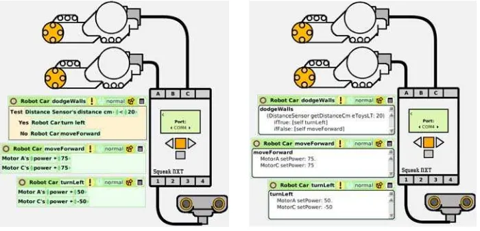
Fig. 1.Implementation of the Robot with
[image:5.595.132.482.380.549.2]Etoys in a visual way
Fig. 2.Implementation of the Robot with
Etoys using code
Depending on the existing platforms, there are different ways we implement this robot behavior. We will show Physical Etoys5
, RobotC6
and Pharo 7 .
Physical Etoys is a visual programming tool that connects the virtual world of computers with the real world in which we live in. With Physical Etoys you can program real world objects (such as robots) to perform interesting tasks, or you can sense the world and use that information to control virtual objects (such as drawings on the screen). The user must grab tiles representing instruc-tions and assembling a script. Figure 1 shows the visual representainstruc-tions of our example using Physical Etoys. If you do not use the predefined tiles to build the script, you can code explcitly the robot and its behavior using Smalltalk8
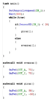
(the embedded programming language) as shown in Figure 2. Robotc is an Integrated development environment targeted towards students that is used to program and control LEGO NXT’s, VEX’s, and RCX robots using a programming language based on C. It aims to allow code to be ported from one robotics platform to another with little or no change in code. You do not have a visual programming environment in RobotC, all robot behaviour must be defined by coding in C as shown in Figure 3. If you use an embedded robot framework in existing program-ming languages, in our case Pharo (a free open-source Smalltalk environment), you can also code the robot behaviour. Figure 4 shows how we code the example using Pharo. Depending on the abstraction level of the programming languages, sometimes we need to deal with specific details of the implementation. For ex-ample, in Pharo we code explicitly how to connect the port and plug the motors previously to specify the desired behavior. These connections are implicit in other platforms.
If we need to represent our example in another platform, we must provide some code transformation from one platform to another one, or even build the application from scratch. But this process is expensive. Our proposal is to build a PIM that allows to abstract the domain concepts and their functionalities using MDD and CBSD. With the generated models we can then derive the code in any specific robotic language. Thus, in our example, we can identify the components Robot, DistanceSensor and Motor, and the functionality is as we described previously.
We can represent this robot with a Component and Behaviour Models rep-resented with their respective UML models. Figure 6 shows a UML Component Diagram that identifies the structural components of the example and which are the required/provided interfaces in their connectors, and Figure 5 shows an Ac-tivity Diagram to model the behaviour of the robot example. Even though these models are useful enough to understand the existing implementation and show the transformation of PSM (code) to PIM (Component and Behavior Models), we could have an intermediate PSM model of objects (due to the fact we are working with object-oriented code) represented with a Class Diagram inferring
5
http://tecnodacta.com.ar/gira/projects/physical-etoys/ 6
http://www.robotc.net 7
http://www.pharo-project.org 8
Fig. 3. Implementation of the Robot with Nxc
| nxt motorA motorC sensorDeDistancia | nxt := LegoNxt new connectOnPort: 'COM4'.
motorA := NxtMotor new plugOn: nxt portA. motorC := NxtMotor new plugOn: nxt portC.
distanceSensor := UltrasonicSensor new plugOn: nxt port1.
[distanceSensor rawValue < 20 ifTrue: [motorA power: 50.
motorC power: -50] ifFalse: [motorA power: 75.
motorC power: 75]] repeat.
Fig. 4.Implementation of the Robot with Pharo
the classes and their relationships based mainly on the code. This last step can be a semi-automatic approach using the initial work done in Passerini work [14]. Due to the space limitations of the paper, we will not present the correspond-ing Class Diagram of our example. Thus, with an abstraction of the concepts represented mainly in Component and Behavior models, we can generate semi-automatically the example in another robot programming language considering that we can have glue code to fill in the code (as we have shown in Pharo).
wall ? Distance Sensor
Walk forward Turn Left
No Yes
Fig. 5.Activity Model of the
Be-haviour of our Example
!!"#$ %#&’&())* +,-(.&/’*0’&-#1*
!!"#$ %#&’&())* 2 #(#1*
!!"#$ %#&’&())* 3#4#(* 5,-(.&/’*
%#6 ’1*
Fig. 6.Component Model of our Example
exam-ple, Figure 8 (Pharo code) shows how we code and connect our example robot to an external component namedKinect Serverthat will indicate if it moves
forwards or backwards depending the movements of arms of the user. In this specific case, we are not able to see the code of the component that models those arms’ movements. However, in Pharo we can design the interfaces that will connect to the external component. In this specific case, the code iskinect := KinectServer new connect. However, in Physical Etoys we can design the
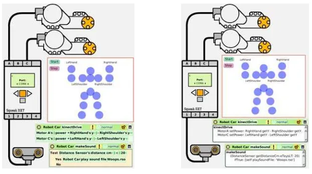
interfaces that will connect to the external component using a visual represen-tation and code (Figures 9 and 10). In our case, they are blue points represent the connections to the external device that deals with arms movements. When we design the interfaces we mean we are not implementing the functionality of the external components, but more than we implement the glue code to be able to connect both components. Even though the internal and external identified components have a similar structure in the models, the way they connect to the robot are different because in the first case the developer implements their inter-faces, and in the second case, the interfaces are already defined and the developer should be able to connect to them by implementing the corresponding glue code. In our specific case in Physical Etoys, it is represented with blue points.
!!"#$ %#&’&())*
+,-(.&/’*0’&-#1*
!!"#$ %#&’&())*
2 #(#1*
!!"#$ %#&’&())*
3#4#(*
!!"#$ %#&’&())*
5,&’/(*0’16’1* 7,-(.&/’*
%#8 ’1*
!"#$%&’($% )*"#$%+’,-./9*
Fig. 7. Component and Service
Models with External Interaction
nxt := LegoNxt new connectOnPort: 'COM4'. motorA := NxtMotor new plugOn: nxt portA. motorC := NxtMotor new plugOn: nxt portC.
distanceSensor := UltrasonicSensor new plugOn: nxt port1.
kinect := KinectServer new connect.
kinect when: #skeletonUpdate evaluate: [:skeleton |
motorA power: skeleton rightHand y - skeleton rightShoulder y. motorC power: skeleton leftHand y - skeleton rightShoulder y].
[distanceSensor rawValue < 20
ifTrue: [nxt playSoundFile: 'Woops.rso']] repeat.
Fig. 8.Implementation of the Robot with Pharo
It is then worth to be able to identify two models: the Component Model shows the internal components, and we build a Service Model that shows the external components. Thus, Figure 7 shows the Component and the Service Models together. In our specific case, our service model is reduced to only one component. In more complex platforms, we can have several services that can be modelled with their respective glue code to be connected to the implemented robots.
of the robots in another specific programming language, keeping the abstract concepts in these models and specific features in PIMs (such as code).
Fig. 9.Implementation of the Robot with
Etoys in a visual way
Fig. 10.Implementation of the Robot with
Etoys using code
5
Conclusions and Future Work
References
1. Microsoft: Microsoft robotics developer studio (March 2009), http://msdn. microsoft.com/en-us/robotics/default.aspx
2. Centro de Altos Estudios en Tecnolog´ıa Inform´atica (CAETI): Proyectos del Area Rob´otica (June 2011),http://www.caeti.uai.edu.ar
3. Gira Grupo de Investigaci´on en Rob´otica Aut´onoma del CAETI: Physical Etoys (May 2011),http://tecnodacta.com.ar/gira/
4. Ando, N., Suehiro, T., Kitagaki, K., Kotoku, T., Yoon, W.: RT-middleware: Dis-tributed component middleware for RT (robot technology). In: Proceedings of the International Conference on Intelligent Robots and Systems 2005 (IROS 2005). pp. 3933–3938 (2005)
5. Arney, D., Fischmeister, S., Lee, I., Takashima, Y., Yim, M.: Model-Based Pro-gramming of Modular Robots. In: Proceedings of 13th IEEE International Sympo-sium on Object/Component/Service-Oriented Real-Time Distributed Computing (ISORC). pp. 66–74 (2010)
6. Barner, S., Geisinger, M., Buckl, C., Knoll, A.: EasyLab: Model-based develop-ment of software for mechatronic systems. In: Proceedings of the IEEE/ASME In-ternational Conference on Mechatronic and Embedded Systems and Applications. Beijing, China. IEEE (2008)
7. Bell, M.: Introduction to Service-Oriented Modeling. Service-Oriented Modeling: Service Analysis, Design, and Architecture. Wiley and Sons (2008)
8. Bell, M.: SOA Modeling Patterns for Service-Oriented Discovery and Analysis. Wiley and Sons (2010)
9. Bruyninckx, H.: Open Robot Control Software: the OROCOS project. In: Pro-ceedings of the 2001 IEEE International Conference on Robotics and Automation, ICRA 2001, Seoul, Korea. pp. 2523–2528. IEEE (2001)
10. Iborra, A., Caceres, D., Ortiz, F., Franco, J., Palma, P., Alvarez, B.: Design of Service Robots. Experiences Using Software Engineering pp. 24–33 (march 2009) 11. Kelly, S., Tolvanen, J.P.: Domain-Specific Modeling. John Wiley and Sons, Inc
(2008)
12. Passerini, N.: Migration from inheritance to composition paradigms. In: Proceed-ings of the CACIC 2011 - ASSE Workshop (2001), submitted for evaluation 13. Pons, C., Giandini, R., P´erez, G.: Desarrollo de Software Dirigido por Modelos.
Teor´ıas, Metodolog´ıas y Herramientas. McGraw-Hill Education (2010)
14. Schlegel, C.: Communication patterns as key towards component interoperability. In: Software Engineering for Experimental Robotics (Series STAR, vol. 30), D. Brugali, Ed. Berlin, Heidelberg. pp. 183–210. Springer-Verlag (2007)
15. Schlegel, C., Hassler, T., Lotz, A., Steck, A.: Robotic Software Systems: From Code-Driven to Model-Driven Designs. In: Proceedings of ICAR 2009 International Conference on Advanced Robotics. IEEE Press (2009)