The Potential for Room Acoustic Active Diffusers
pacs 43.55.Br, 43.20.El, 43.50.Ki
Cox, Trevor J.; Avis, Mark R.; Xiao, Lejun. Acoustics and Electronic Engineering University of Salford
Salford M5 4WT UK
Tel: +44 161 295 5474 Fax: +44 870 137 1611 [email protected]
ABSTRACT
Diffusing devices are used to improve room acoustics in a wide variety of applications. The dispersion of current diffuser technology is often limited to mid to high frequencies because low frequency diffusers are usually too large to be easily accommodated. To extend the bandwidth of diffusers to a lower frequency a new approach is required; it is proposed to use active control technology. In particular, active impedance techniques are being exploited to create diffusion rather than the more usual absorption. This paper will present a conceptual design for an active diffuser and some simulation results demonstrating its utility.
INTRODUCTION
It is common to control the acoustics of a space by treating the boundary surfaces with appropriate combinations of reflective, absorptive and diffusive material. In recent decades, there has been increased interest in and use of diffusers to improve room acoustics. Diffusers are most often used in spaces where acoustics is a critical requirement1. They are used to improve speech intelligibility in railway stations, theatres and teleconferencing rooms. Diffusers are also used in auditoria, music practice and listening rooms where the quality of music is important. So far, diffusers have been based on passive devices. This concept paper is about the development of a new generation of diffusers using active technologies. Active devices potentially offer significant advantages over passive devices; in particular, an active surface should provide wider bandwidth diffusion.
generated below a few thousand Hertz). An active device offers the possibility of producing a diffuser that works at a lower frequency from a given available depth when compared to a passive device.
Another limitation in diffuser design comes from the visual requirements of interior designers5. A good diffuser must be a unified part of the architectural design, rather than an obvious add-on. While it is possible to achieve rough surfaces that are pleasing to many, there is an appeal in having a flat surface that creates diffusion. Potentially, active surfaces could form surfaces that appear to be visually flat and uniform, but are actually acoustically diffusing. A final advantage that an active surface has over a passive device is that variability can be easily achieved. Many rooms have to be multi-purpose, and active elements have the potential to enable the acoustics of a space to be easily changed.
ACTIVE IMPEDANCE
There is a large body of knowledge on the use of active control to alter acoustic environments. These have, however, centred on the suppression of noise or resonant modes, and the addition of reflections to enhance reverberation, rather than the dispersion of reflections. Most relevant to this project is the active control of surface impedance, as the diffusers described here will use impedance differences across their surface to achieve wave dispersion.
The first description of actively controlled impedance was made by Olson and May6 in the context of a sound absorber, but practical systems were not in general feasible until advances in digital computers from the 1980s onwards. Much subsequent research centred on the active minimisation of a sound field, with many papers originating from Nelson and Elliot7. Guiking, Karcher and Rollwage report useful early work on impedance control8, but it is left to Nicholson and Darlington at Salford University9 and Nelson and Orduna-Bustamente at Southampton University10 to identify the primary techniques. The principle differences between these techniques lay in the method of measuring the surface impedance. Nicholson and Darlington used direct transduction of an electrodynamic loudspeaker using a microphone and accelerometer to derive an error signal which was minimised by control hardware, whereas Nelson and Orduna-Bustamente used the two microphone method of Chung and Blaser11. Both groups produced similar control regimes and either might have been adopted for the active diffuser. For historical reasons the Salford University regime has been chosen in this work. More recent research on active absorption has concerned the construction of hybrid acoustic impedances, where a passive porous element is used in conjunction with an adaptively controlled loudspeaker in order to achieve wider bandwidth absorption (e.g. Furstoss et al12). This body of work concerning active impedance control is being built upon in developing active diffusers; it must be remembered that the choice of target impedance will be different, and considerable development is required to achieve stable feedback operation.
PROPOSED STRUCTURE
Figure 1 shows the structure for the first prototype actively diffusing surface. A Schroeder diffuser profile is being used with active elements substituting for one or more of the wells. Passive Schroeder diffusers break up the reflected wavefront using phase-changes introduced by the waveguides of differing length on which the sound is incident. Plane waves are excited by this wavefront, and take different times to propagate up and down the wells of various depth. Consequently, the simplest model for an active system uses the active elements to produce additional low frequency diffusion by controlling the well termination impedance and simulating a deeper well. Such a Schroeder-style device is appealing for many reasons:
• There is a considerable body of work concerning the design of passive Schroeder devices, and this can be built upon to give an appropriate active design.
• Passive Schroeder diffusers have been commercially successful in many applications, and it is probable that the work will produce a device that is potentially useful in real applications, and not just of academic interest.
[image:3.596.151.442.167.315.2]The high frequency diffusion is provided by the passive elements in the Schroeder diffuser, and the active elements deal with the low frequencies. There is a complementary relationship between the passive and active elements, as each operates within the frequency range they work best.
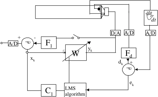
Figure 2 shows an adaptive active control system which has previously been applied to the problem of resonant modes in rooms. The method has been termed ‘active impedance control’ and relies on the specification of a desired surface impedance at the control source (a conventional electrodynamic loudspeaker driver, shown at the right-hand end of the duct in Figure 2). The difference between the active acoustic impedance controller and an archetypal filtered-x LMS control system13 resides in the derivation of the desired signal dk. The control
loudspeaker is instrumented with a microphone and accelerometer; the accelerometer output is then integrated with respect to time giving a signal proportional to cone velocity. Therefore it is possible to directly measure the specific acoustic impedance at the cone surface.
Figure 1 Active diffusers based on Schroeder diffusers.
<
+
x
ky
kd
ke
kLMS algorithm
W
C
1D/A
-A/D
A/D
E
+
F
1A/D
E
I
dt
F
d [image:3.596.139.466.547.748.2]Filter Fd acts on the microphone output. The coefficients are set to give a response equal to the
inverse of the desired impedance at the cone. The output from Fd is therefore a desired velocity
dk, which is compared with the actual velocity in order to derive the error signal ek. Filter C1
contains the plant model. As with any adaptive filtering, the LMS update gain determines the speed at which the specific acoustic impedance at the cone converges to the value chosen by the specification of Fd. High update gains often cause instability in LMS operations.
The system may be configured in either a feedforward or feedback topology, depending on the source of reference input xk. If driven from the signal generator which feeds the primary sound
sources in a room, the system will be feedforward. This is a useful regime for developing and testing systems, since ensuring stable operation is reasonably straightforward. In the long term, however, this approach is limited as it only works where the primary sound field is generated electroacoustically. Alternatively the reference input may be connected to an external measurement microphone, or one of the transducers which instrument control source velocity and cone pressure. In this feedback case, compensation filter F1 is required to ensure stable
operation over the widest possible operating bandwidth. The ultimate goal in the development of active diffusers is to use the latter, feedback configuration, as it is most generally applicable to sound production and reproduction.
Any practical realisation of the active impedance controller implies that appropriate arrangement must be made for the transduction of the impedance at the surface of the control source. In published investigations in a one-dimensional test environment14,15, a termination consisting of driver instrumented with an accelerometer and an omnidirectional electret microphone capsule was employed. The output from the accelerometer was integrated and the pressure and velocity signals used as control inputs to derive a control signal which aimed to force the ratio of cone pressure to velocity to a real and characteristic value. These arrangements have been kept for the current active diffuser work, although the target impedance required in the diffusing application is naturally very different from the impedance required of an active absorber.
SIMULATIONS
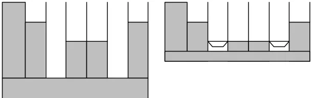
Initial simulations of the above system have investigated the use of an active diffuser to replace the longest wells within a Schroeder diffuser. Figure 3 shows an N=7 passive Quadratic Residue Diffuser (QRD), and a suggested active design. The active design occupies a little over half the depth of the passive design, so there is potential for wider bandwidth operation from a given depth. The task of the active elements is to make the wells look longer than they physically are. Consequently, the desired impedance will be a -jcot(kd) function, where k is the wavenumber and d the additional depth required for the active well. In the active controller shown in Figure 2, the inverse of the desired impedance – the desired admittance - is represented in Fd as an FIR or IIR filter. Simulations have indicated that in a diffuser application,
Fd is best represented in an IIR configuration. Fd has to approximate a jtan(kd) function, which
[image:4.596.144.453.635.731.2]has a series of singularities that cannot be exactly replicated by a stable filter. Consequently, initial simulations have investigated the compromise between filter stability and successful active diffusion performance.
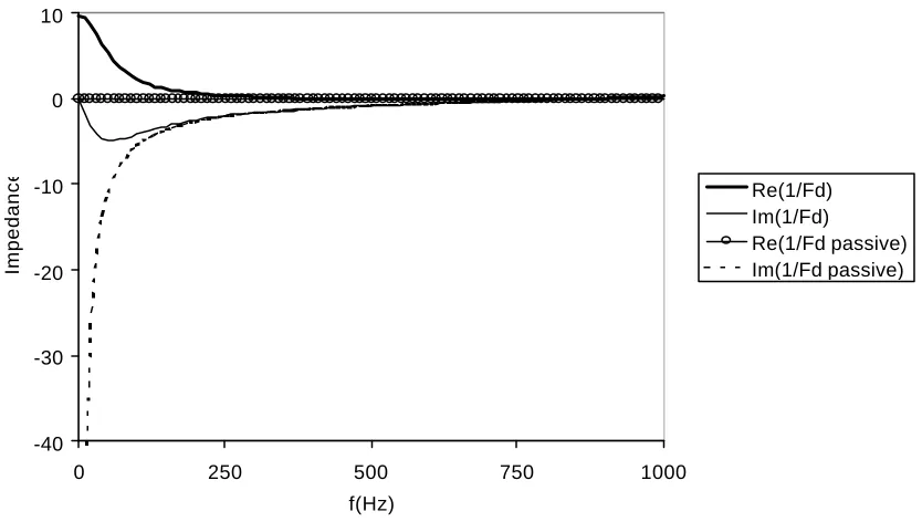
A practical desired admittance can be obtained if a small loss is allowed in the active well. Figure 4 shows the impedance at the controller surface. The lines marked passive show the real and imaginary parts of the specific acoustic termination impedance for a longer well without an active device present. If the controller could achieve this impedance, then the active diffuser would behave in exactly the same way as a passive device with deeper wells. The other lines represent the impedance achieved by an IIR filter design. The small resistive term mentioned previously has been added - in the case shown, this real part has a normalised specific acoustic impedance of about 0.02. This small resistance causes inaccuracies in the impedance at low frequency, but these are frequencies are below those of interest for this device; this simulation uses a design frequency of 500Hz.
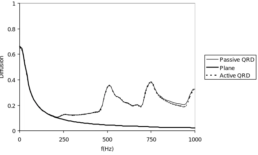
Figure 5 shows the diffusion verses frequency for a passive and active diffuser. A plane surface is also shown as a reference. The diffusion is calculated using AES-4id-200116, although in this case narrow band evaluation rather than 1/3 octave averaging is used. The higher the value of the diffusion coefficient, the more even the dispersion. There is very little difference in the performance of the active and passive devices. Some small discrepancies can be seen as the frequency increases. The virtual extension simulated by the active controller has a resonance at 875Hz, and close to the resonance the match between the passive and active admittance, Fd,
becomes poorer.
Conclusions
The available depth often limits the low frequency performance of diffusers. By employing active control techniques, it should be possible to produce virtual well extensions and so get improved performance. This paper has outlined the concept of such an active diffuser. The control regime under development has been described, and some simulation results supporting this approach presented. Many design and practical problems remain for further consideration, but it appears that in principle the approach should lead to the development of a new type of diffuser.
-40 -30 -20 -10 0 10
0 250 500 750 1000 f(Hz)
Impedance
Re(1/Fd) Im(1/Fd)
[image:5.596.89.506.198.434.2]Re(1/Fd passive) Im(1/Fd passive)
REFERENCES
1
P.D’Antonio & T.J.Cox, “Diffusor application in rooms,” Applied Acoustics. 60. 113-142. (2000).
2
M. R. Schroeder, “Binaural dissimilarity and optimum ceilings for concert halls: more lateral sound diffusion,” J.Acoust.Soc.Am. 65, 958-963 (1979).
3
P. D’Antonio and T. J. Cox, “Two decades of sound diffusor design and development. part1: applications and design,” J.Audio.Eng.Soc. 46(11) 955-976. (1998).
4
P. D’Antonio and T. J. Cox, “Two decades of sound diffusor design and development. part1: applications and design,” J.Audio.Eng.Soc. 46(11) 955-976. (1998).
5
T. J. Cox and P. D’Antonio, “Holistic diffusers,” proc. IoA(UK). 21(6) 201-206. (1999).
6
H. F. Olson & E. G. May, “Electronic sound absorber,”J.Acoust.Soc.Am.25 1130-1136, (1953).
7
P. A. Nelson and S. J. Elliot, ”Active control of sound,” Academic Press, Cambridge, (1995).
8
D. Guiking, K. Karcher, and M. Rollwage, “Coherent active methods for applications in room acoustics,” J.Acoust.Soc.Am.78 1426-1434, (1985).
9
G. C. Nicholson, “The active control of impedance,” PhD Thesis, University of Salford, (1995).
10
F. Orduna-Bustamante, and P. A. Nelson, “An adaptive controller for the active absorption of sound,” J.Acoust.Soc.Am. 91 2740-2747, (1992).
11
J. Y. Chung and D. A. Blaser, “Transfer function method of measuring in-duct acousic properties,” J.Acoust.Soc.Am. 68 907-921, (1980).
12
M. Furstoss, D. Thenail and M. A. Galland, “Surface impedance control for sound absorption: direct and hybrid passive/active strategies,” J.Sound.Vib. 203(2) 219-236, (1997).
13
B. Widrow & S.D. Stearns, “Adaptive signal processing,” Prentice Hall, (1985).
14
G. C. Nicholson and P. Darlington, “Smart surfaces for building acoustics,” Proc. IOA 13(8) 155-164, (1991).
15
G. C. Nicholson and P. Darlington, “Active control of acoustic absorption, reflection and transmission,” Proc.IOA 15(3) 403-409, (1993).
16
AES-4id-2001 “AES information document for room acoustics and sound reinforcement systems - Characterisation and measurement of surface scattering uniformity”. J.Audio.Eng.Soc. 49(3) 149-165. (2001).
0 0.2 0.4 0.6 0.8 1
0 250 500 750 1000 f(Hz)
Diffusion
[image:6.596.96.510.83.332.2]Passive QRD Plane Active QRD