Micromechanics as a Testbed for Artificial
Intelligence Methods Evaluation
Ernst Kussul1, Tatiana Baidyk1, Felipe Lara-Rosano1, Oleksandr Makeyev2, Anabel Martin1 and Donald Wunsch3
1 Center of Applied Sciences and Technological Development, National Autonomous University of Mexico, Cd. Universitaria, Circuito Exterior s/n,
Coyoacán, 04510, México, D.F., Mexico
ekussul@servidor.unam.mx; tbaidyk@aleph.cinstrum.unam.mx; lararf@servidor.unam.mx; anabelmartin@lycos.com 2 Dept. of Electrical and Computer Engineering, Clarkson University,
5720, Potsdam, NY 136992, USA mckehev@hotmail.com
3 Applied Computational Intelligence Lab, Dept. of Electrical and Computer Engineering, University of Missouri-Rolla, 1870 Miner
Circle, Rolla MO 65409, USA dwunsch@ece.umr.edu
Abstract. Some of the artificial intelligence (AI) methods could be used to improve the performance of automation systems in manufacturing processes. However, the application of these methods in the industry is not widespread because of the high cost of the experiments with the AI systems applied to the conventional manufacturing systems. To reduce the cost of such experiments, we have developed a special micromechanical equipment, similar to conventional mechanical equipment, but of a lot smaller overall sizes and therefore of lower cost. This equipment can be used for evaluation of different AI methods in an easy and inexpensive way. The methods that show good results can be transferred to the industry through appropriate scaling. This paper contains brief description of low cost microequipment prototypes and some AI methods that can be evaluated with mentioned prototypes.
1 Introduction
brief description of micromechanical devices that have been developed and used in our work. In the third section we describe image recognition systems based on neural networks and their applications in micromechanical equipment automation. The fourth section contains description of a new problem in micromechanical manufacturing that can be solved by the methods based on neural networks.
2 Development of micromechanical equipment
The main idea of low cost micromechanical equipment manufacturing is the following: each new micro device should be manufactured by micromachine tools and micro assembly devices which have the overall sizes comparable with the overall sizes of work pieces to be manufactured. For example, if new microdevice contains the shaft of 0.2mm diameter and of 0.8mm length then this shaft is to be manufactured with the lathe with the overall sizes of 4mm * 4mm * 4mm. In most cases the lathe of such overall sizes will automatically have tolerances that coincide with the shaft specifications. The main errors of machine tools that originate from thermal expansions, vibrations, elastic deformations etc. are proportional to the overall sizes of the machine tool [20]. So if we manufacture the micro shaft with the lathe that has 25 times smaller overall sizes than the overall sizes of the conventional lathe then we can decrease the tolerances 25 times. The low end lathe of conventional overall sizes has tolerances of about 0.05mm, so our micro lathe should have tolerances of about 0.002mm. It is sufficient for most applications of said micro shaft. Low end conventional lathe has low cost. Our micro lathe should have even lower cost due to low consumption of materials, work area and energy.
To examine the possibility of production of micromachine tools that have low cost components we have developed 2 prototypes of micromachine tools with the cost of components of less than $100. One of these prototypes is shown in Fig. 1.
Fig. 1. Micromachine tool prototype: 1 – Y-direction drive; 2 - Y-direction guides; 3 – X-direction guides; 4 – X-X-direction carriage; 5 – X-X-direction drive; 6 – X-direction guides; 7 – Z-direction carriage; 8 – Z-Z-direction drive motor; 9 – Z-Z-direction drive gearbox; 10 – chuck support; 11 – chuck; 12 – cutter and measurement tool support
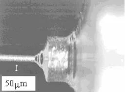
Japanese researchers turned the brass needle of 0.05mm diameter to show the possibility of micro turning [21]. They used micro lathe which has expensive components (some thousands dollars). We repeated their results (Fig. 2) with micromachine tool that has very cheap components (less than $100).
Fig. 2. Brass needle of 50 µm diameter manufactured with the first micromachine tool prototype
[image:3.595.239.368.441.536.2]3 Computer vision systems for micromechanical applications
To obtain high precision in low cost microequipment we use adaptive algorithms based on computer vision systems.
3.1 Image recognition in micro assembly
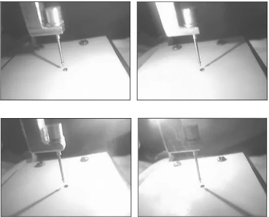
The first problem which we dealt with was the problem of micro assembly. To introduce the pin into the hole it is necessary to collocate them with close tolerances. Low cost microequipment does not permit such collocation without adaptive algorithms. Neural network image recognition system was created to recognize the mutual pin-hole position. To investigate the potential of this system we created the image database that contains 441 images with different mutual positions of pin and hole. For this purpose we used the prototype shown in Fig. 4.
In our system we used one TV camera for teleconferences and four light sources [11]. The shadows from different light sources (Fig. 5) permit us to obtain the 3-D position of the pin relative to the hole. We use a neural classifier LIRA (Limited Receptive Area) to recognize this position [12]. The input of our neural classifier is an image that is a combination of four images of one pin-hole position that correspond to different light sources. This image is processed and the contours are extracted (Fig. 6). The output of the neural classifier gives the X and Y coordinates of
pin relative to the hole.
If this position is recognized with the precision of 0.1mm then the recognition rate is sufficiently high: 99.5% for X coordinate and 89.9% for Y coordinate.
[image:4.595.156.449.107.237.2]Fig. 4. Micro assembly system controlled by the vision system
Fig. 5. An example of four images of the same pin-hole position obtained with different light sources
[image:5.595.170.436.328.542.2]Fig. 6. An example of the input image of the LIRA neural classifier
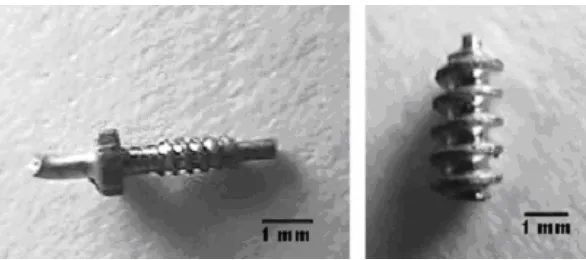
Fig. 7. Examples of micro screws manufactured with different mutual positions of cutters
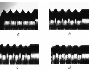
It is difficult to evaluate the mutual position of cutters directly. That is why we propose to evaluate the correctness of their mutual position using the shape of the first screw that is manufactured with the lathe. If the distance between the second cutter and the lathe axis is less than necessary then the shape of the thread will be like the one presented in Fig. 7, a. If this distance is larger than necessary then the
shape of the thread will be like ones in Fig. 7, c, d.
We have produced 40 screws of 3mm diameter with the CNC-lathe Boxford. Ten screws were produced with correct position of the thread cutter (Fig. 15, b). Thirty
screws were produced with erroneous positions of the cutter.
Ten of them (Fig. 15, a) had the distance between the cutter and the screw axis
0.1mm smaller than necessary. Ten screws (Fig. 15, c) were produced with the
distance 0.1mm larger than necessary and the remaining ten (Fig. 15, d) with the
[image:6.595.217.390.314.449.2]selected images from each group were used for the neural classifier’s training and the other five were used for the neural classifier’s testing.
The best recognition rate in shape recognition obtained with the PCNC neural classifier (Permutation Coding Neural Classifier) was 92.5% [22].
3.3 Texture recognition
The third task was the recognition of surface textures. This is the issue of the day for the quality inspection systems and sometimes for work piece orientation recognition in the assembly process. For this task we developed the texture recognition system based on the RSC (Random Subspace) neural classifier [23].
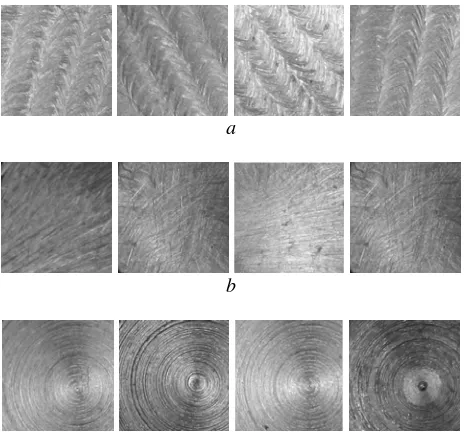
To test our texture recognition system we created our own image database of metal surface images. Four texture classes correspond to metal surfaces after: milling, polishing with sandpaper and turning with lathe (Fig. 8).
a
b
[image:7.595.187.419.284.502.2]c
Fig. 8. Examples of metal surfaces after: a) milling, b) polishing with sandpaper, c) turning
with lathe
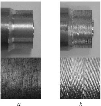
Fig. 9. Work piece and its surface: a) without resonant oscillations, b) with resonant
oscillations
For comparison, an example of the work piece that was manufactured with resonant oscillation is presented in Fig. 9, b. Many factors affect the resonance oscillations
appearance. We intent to prove the connectionist neural network approach for prediction of resonant oscillations. We also want to try to apply the adaptive critic design methods to the optimal control of cutting process under resonant oscillations condition [24].
Acknowledgements
References
1. Eberhart, R.: Overview of computational intelligence [and biomedical engineering applications]. Proceedings od the 20-th Annual International Conference of the IEEE Engineering in Medicine and Biology Society 3 (1998) 1125-1129
2. Hui, T., Brown, D., Haynes, B., Xinxian Wang: Embedded e-diagnostic for distributed industrial machinery. IEEE International Symposium on Computational Intelligence for Measurement Systems and Applications (2003) 156-161
3. Awadallah, M., Morcos, M.: Application of AI tools in fault diagnosis of electrical machines and drives-an overview. IEEE T Energy Conver 18, Issue 2 (2003) 245-251 4. Werbos, P.: Advanced Forecasting Methods for Global Crisis Warning and Models of
Intelligence. In: General Systems Yearbook 22 (1977) 25-38
5. Prokhorov, D., Wunsch, D.: Adaptive Critic Designs. IEEE T Neural Networ 8, N 5 (1997) 997-1007
6. Xiaoou Li, Lara-Rosano, F.: A weighted fuzzy Petri net model for knowledge learning and reasoning. International Joint Conference on Neural Networks, IJCNN '99 4 2368 –2372 7. Xiaoou Li, Wen Yu, Lara-Rosano, F.: Dynamic Knowledge Inference and Learning under
Adaptive Fuzzy Petri Net Framework. IEEE T Syst Man Cy 39, N4 (2000) 442-450 8. Bottou, L., Cortes, C., Denker, J., Drucker, H., Guyon L., Jackel L., LeCun J., Muller U.,
Sackinger E., Simard P., Vapnik V.: Comparison of Classifier Methods: a Case Study in Handwritten Digit Recognition. In: Proceedings of 12th IAPR International Conference on Pattern Recognition 2 (1994) 77-82
9. Fukushima, K. Neocognitron: A hierarchical neural network capable of visual pattern recognition. Neural Networks 1 (1988) 119-130
10. Roska, T., Rodriguez-Vazquez, A.: Toward visual microprocessors. Proceedings of the IEEE 90, Issue 7 (July 2002) 1244-1257
11. Baidyk, T.: Application of Flat Image Recognition Technique for Automation of Micro Device Production. Proceedings of the International Conference on Advanced Intelligent Mechatronics “AIM’01”, Italy (2001) 488-494
12. Baidyk, T., Kussul, E., Makeyev, O., Caballero, A., Ruiz, L., Carrera, G., Velasco, G.: Flat image recognition in the process of microdevice assembly. Pattern Recogn Lett 25/1
(2004) 107-118
13. Kussul E.M., 1992, Associative Neural Structures. Kiev, Naukova Dumka, 144p. (in Russian).
14. Amosov N.M., Baidyk T.N., Goltsev A.D., Kasatkin A.M., Kasatkina L.M., Kussul E.M., Rachkovski D.A., 1991, Neurocomputers and Intelligent Robots. Kiev, Naukova Dumka, 272 p. (in Russian).
15. Baidyk T.N., 2001, Neural Networks and Artificial Intelligence Problems. Kiev, Naukova Dumka, 264 p. (in Russian).
16. Kussul, E., Rachkovskij, D., Baidyk, T., Talayev, S.: Micromechanical Engineering: a Basis for the Low-cost Manufacturing of Mechanical Microdevices Using Microequipment. J Micromech Microeng 6 (1996) 410-425
17. Kussul, E., Baidyk, T., Ruiz-Huerta, L., Caballero, A., Velasco, G., Kasatkina, L.: Development of Micromachine Tool Prototypes for Microfactories. J Micromech Microeng
12 (2002) 795-812.
18. Kussul E., Baidyk T., Ruiz L., Caballero A., Velasco G., 2002, Development of Low-cost Microequipment. 2002 International Symposium on Micromechatronics and Human Science, IEEE, Nagoya, Japan, Oct. 20-23, pp.125-134.