ADVERTIMENT. La consulta d’aquesta tesi queda condicionada a l’acceptació de les següents condicions d'ús: La difusió d’aquesta tesi per mitjà del servei TDX (www.tesisenxarxa.net) ha estat autoritzada pels titulars dels drets de propietat intel·lectual únicament per a usos privats emmarcats en activitats d’investigació i docència. No s’autoritza la seva reproducció amb finalitats de lucre ni la seva difusió i posada a disposició des d’un lloc aliè al servei TDX. No s’autoritza la presentació del seu contingut en una finestra o marc aliè a TDX (framing). Aquesta reserva de drets afecta tant al resum de presentació de la tesi com als seus continguts. En la utilització o cita de parts de la tesi és obligat indicar el nom de la persona autora.
ADVERTENCIA. La consulta de esta tesis queda condicionada a la aceptación de las siguientes condiciones de uso: La difusión de esta tesis por medio del servicio TDR (www.tesisenred.net) ha sido autorizada por los titulares de los derechos de propiedad intelectual únicamente para usos privados enmarcados en actividades de investigación y docencia. No se autoriza su reproducción con finalidades de lucro ni su difusión y puesta a disposición desde un sitio ajeno al servicio TDR. No se autoriza la presentación de su contenido en una ventana o marco ajeno a TDR (framing). Esta reserva de derechos afecta tanto al resumen de presentación de la tesis como a sus contenidos. En la utilización o cita de partes de la tesis es obligado indicar el nombre de la persona autora.
Universitat Polit`ecnica de Catalunya Electrical Engineering Department
PhD Thesis
Analysis of the contribution of
wind power plants to damp
power system oscillations
Author:
Jos´
e Luis Dom´ınguez-Garc´ıa
Advisors:
Dr. Oriol Gomis-Bellmunt
Dr. Fernando D. Bianchi
Catalonia Institute for Energy Research (IREC) Electrical Engineering Research Area
Jardins de les Dones de Negre 1 2nd floor, 08930 Sant Adri`a de Bes`os, Barcelona, Spain
Copyright c Jos´e Luis Dom´ınguez-Garc´ıa, 2013
Acta de qualificació de tesi doctoral Curs acadèmic:
Nom i cognoms
DNI / NIE / Passaport
Programa de doctorat
Unitat estructural responsable del programa
Resolució del Tribunal
Reunit el Tribunal designat a l'efecte, el doctorand / la doctoranda exposa el tema de la seva tesi doctoral titulada
__________________________________________________________________________________________
_________________________________________________________________________________________.
Acabada la lectura i després de donar resposta a les qüestions formulades pels membres titulars del tribunal,
aquest atorga la qualificació:
APTA/E NO APTA/E
(Nom, cognoms i signatura)
President/a
(Nom, cognoms i signatura)
Secretari/ària
(Nom, cognoms i signatura)
Vocal
(Nom, cognoms i signatura)
Vocal
(Nom, cognoms i signatura)
Vocal
______________________, _______ d'/de __________________ de _______________
El resultat de l’escrutini dels vots emesos pels membres titulars del tribunal, efectuat per l’Escola de Doctorat, a
instància de la Comissió de Doctorat de la UPC, atorga la MENCIÓ CUM LAUDE:
SÍ NO
(Nom, cognoms i signatura)
Presidenta de la Comissió de Doctorat
(Nom, cognoms i signatura)
Secretària de la Comissió de Doctorat
Abstract
Wind power has emerged as one of the most promising renewable energy sources. The very penetration levels of wind energy in power systems have altered several aspects of power system operation, such as system stability. Owing to the large penetration of wind power, transmission system opera-tors (TSOs) have established special grid codes for wind farms connection. These grid codes require wind farms to provide ancillary services to the grid such as frequency and voltage regulation. In the near future, the capability of damping power system oscillations will be required. As a result of the development of such requirements, the concept of wind power plant (WPP) arises being defined as a wind farm which is expected to behave similarly to a conventional power plant in terms of power generation, control and ancillary services.
II
To answer these questions, this thesis conducts research on proper selec-tion of input-output signal pairs to damp out electromechanical oscillaselec-tions using wind power plants without drawing attention to a particular control design. This is necessary conclusions about the power system independently of a particular controller. The capability to damp is an intrinsic characteris-tic of the system and should not be affected by a parcharacteris-ticular controller (PSS). Firstly, different analysis techniques are compared, considering both control-lability and observability measures and input-output interactions. This en-ables recommendations to be drawn so as to the selection of the the best sig-nal pairs to damp power system oscillations considering different approaches, such as single-input single-output (SISO) and multivariable control (MIMO). Second, a new criterion to select the best input-output signals used by a PSS based on WPPs is presented, considering explicitly local and remote signals in the analysis. Taking into account fundamental design limitations and using controllability and observability concepts, the criterion is able to iden-tify the most suitable pair of input-output local signals without consider any particular controller.
Resum
L’energia e`olica s’ha convertit en una de les fonts d’energia renovable m´es prometedores. Actualment, l’elevat nivell de penetraci´o de l’energia e`olica a la xarxa el`ectrica ha condu¨ıt a la modificaci´o del comportament de diversos aspectes d’aquesta, com per exemple, l’estabilitat. Degut a aquesta gran penetraci´o, els operadors de xarxes de transmissi´o (TSOs) han establert procediments d’operaci´o especials per a la connexi´o de grans parcs e`olics. Aquests codis requereixen als parcs elics que realitzin serveis auxiliars al sistema el`ectric com, per exemple, la regulaci´o de freq¨u`encia i la regulaci´o de la pot´encia reactiva. En un futur proper, la capacitat dels parcs e`olics per esmorteir les oscil·lacions del sistema de pot`encia es requerir`a (en l’actualitat ja existeixen esborranys de nous procediments d’operaci´o que ho inclouen). A causa d’aquest requeriments, el concepte de central de generaci´o d’energia e`olica es defineix com un parc e`olic que s’espera que es comporti de manera similar a una central de generaci´o el`ectrica convencional en termes de poder realitzar tasques tals com generaci´o, control i serveis auxiliars.
IV
de les centrals e`oliques als generadors s´ıncrons s´on factors cr´ıtics. D’aquest fet surgeixen algunes preguntes com: ´Es aquest el factor m´es cr´ıtic? Com es pot assegurar una contribuci´o adequada, si m´es no la millor resposta possi-ble, per ajudar a estabilitzar el sistema el`ectric? Es poden asegurar quina ser`a la contribuci´o a l’estabilitat del sistema el`ectric independentment de la xarxa i l’esquema de control escollit?
Per respondre a aquestes preguntes, aquesta tesi ha realitzat investiga-cions sobre l’adequada selecci´o de parells de senyals d’entrada-sortida per esmorteir les oscil·lacions electromec`aniques amb centrals e`oliques evitant dissenyar el controlador i propossant met`odes f`acilment adaptables a qual-sevol sistema el`ectric. En primer lloc, s’han comparat diferents t`ecniques d’an`alisi tenint en compte tant les mesures de controlabilitat i observabil-itat com les interaccions entre les senyals d’entrada i sortida. D’aquesta comparaci´o, certes recomanacions es donen a l’hora de seleccionar els mil-lors parells de senyals per esmorteir les oscil·lacions del sistema el`ectric de pot`encia considerant diferents esquemes de control com ara entrada ´unica sortida ´unica (SISO) i control multivariable (MIMO). En segon lloc, s’ha pro-posat un nou criteri per seleccionar les senyals d’entrada i sortida utilitzades per un control estabilitzador per centrals d’energia e`olica. On, a difer`encia amb anteriors met`odes de selecci´o proposats, el criteri presentat considera expl´ıcitament tant senyals locals com senyals remotes dins el seu an`alisi. Aquest criteri ´es capa¸c d’identificar la parella de senyals locals d’entrada i sortida m´es adequada sense realitzar el disseny del controlador, considerant tant les limitacions fonamentals del disseny del controlador imposades per el sistema com els conceptes de controlabilitat i observabilitat.
V
Acknowledgements
This work has been carried out at the Electrical Engineering Research Area (EERA) of Catalonia Institute for Energy Research (IREC). This thesis has been financially supported by IREC through the 01–10 WIND ENERGY grant.
First of all, I would like to express my sincere gratitude to my supervisors Dr. Oriol Gomis-Bellmunt and Dr. Fernando D. Bianchi for their supervi-sion, their guidance and encouragement. I would like to thank them also their kind advices which keep me inside the real and applied engineering boundaries, even when my thoughts and ideas tried to runaway.
I am also extremely grateful to all my EERA–IREC colleagues (L´azaro, Jordi, Luc´ıa, Cristina, Miguel, David, Albert, Gerard, Oscar, Joaquim, Ig-nasi Andi and Manel) for the interesting discussions during all this time. I would like to thank specially to Mikel and Francisco for their helping and friendship.
I sincerely thank all the Institute of Energy at Cardiff University for make me feel like at home during my stay there. Special mention to Dr. Carlos Ugalde-Loo who also contributes in this thesis, Dr. John Licari and Dr. Luke Livermore for all their help and friendship.
Contents
Abstract I
Resum III
Acknowledgement VII
Table of Contents IX
List of Tables XIII
List of Figures XV
Acronyms XXI
1 Introduction 1
1.1 Research motivations and objectives . . . 3
1.2 Thesis contributions . . . 5
1.3 Thesis outline . . . 5
2 Power systems background 7 2.1 Power system stability . . . 7
2.2 Power system representation . . . 10
2.2.1 Lines and cables modelling . . . 11
Contents X
2.2.3 Synchronous generator modelling . . . 12
2.2.4 Wind power plant . . . 13
2.2.5 Wind power plant modelling . . . 17
2.3 Mathematical basis of small signal stability . . . 18
2.3.1 Eigenvalues . . . 19
2.3.2 Eigenvectors and participation factor . . . 21
3 Literature review of power oscillation damping supported by wind power 23 3.1 Introduction . . . 23
3.2 The impact of wind farms in power system oscillations . . . . 24
3.2.1 Oscillations in power system with wind farms . . . 24
3.2.2 Inherent oscillations of wind turbines . . . 27
3.3 Damping control for wind turbine inner oscillations . . . 29
3.3.1 Mechanical regulation . . . 30
3.3.2 Converter-based regulation . . . 31
3.4 Control of wind farms for enhancing the damping of power system oscillations . . . 32
3.4.1 Active power regulation . . . 33
3.4.2 Reactive power regulation . . . 38
3.4.3 Active and reactive power regulation . . . 39
3.5 Conclusions of the chapter . . . 41
4 Comparative analysis of power system stabilizer capability of wind power plants 45 4.1 Introduction . . . 45
4.2 Power system stabilizers for wind turbines . . . 46
4.3 Case studies . . . 47
4.3.1 PSS controller of WPP . . . 49
4.3.2 Case 1: Comparison of different PSS schemes . . . 50
4.3.3 Case 2: Effect of cable length on PSS capability . . . 54
4.3.4 Case 3: Effect of WPP location on PSS capability . . 58
4.4 Discussion and conclusions of the chapter . . . 62
5 Input-output signal selection for damping of power system oscil-lations using wind power plants 63 5.1 Introduction . . . 63
5.2 Power system oscillation damping contribution using wind power plants . . . 64
XI Contents
5.3.1 Controllability and observability measures . . . 66
5.3.2 Limitations caused by right hand plane zeros (RHPZs) 69 5.3.3 Input-output interactions . . . 69
5.4 Case of study . . . 73
5.4.1 Linearization . . . 74
5.4.2 Controllability and observability measures comparison 75 5.4.3 RPHZs . . . 77
5.4.4 Input-output interactions . . . 79
5.4.5 Simulations . . . 83
5.4.6 Recommendations for input-output pair selection . . . 87
5.5 Conclusion of the chapter . . . 89
6 Control signal selection for damping oscillations with wind power plants based on fundamental limitations 91 6.1 Introduction . . . 91
6.2 Power System Stabilization based on WPPs . . . 92
6.3 Fundamental limitations in control design . . . 93
6.3.1 Controllability and Observability . . . 93
6.3.2 Design limitations caused by feedback . . . 95
6.4 Input-Output Selection Criterion . . . 97
6.5 Case of study 1: Single machine infinite bus system with wind power plant generation . . . 99
6.5.1 Selection of the most adequate input-output pair . . . 101
6.5.2 Frequency and transient responses . . . 104
6.6 Case of study 2: Three machines system with wind power plant generation . . . 107
6.6.1 Selection of the most adequate input-output pair . . . 110
6.6.2 Frequency and transient responses . . . 114
6.7 Conclusions of the chapter . . . 117
7 Effect of non-standard operating frequencies on the economic cost of offshore AC networks 119 7.1 Introduction . . . 119
7.2 What is the SuperNode? . . . 122
7.3 Frequency-cost dependence of SuperNode components . . . . 123
7.3.1 Cables . . . 123
7.3.2 Transformer design . . . 128
7.3.3 Reactive power compensation . . . 132
7.3.4 Offshore infrastructure . . . 133
Contents XII
7.4.1 Cables . . . 136
7.4.2 Main electrical devices . . . 139
7.4.3 Infrastructure costs . . . 142
7.4.4 Total capital cost of the SuperNode . . . 143
7.5 Conclusions of the chapter . . . 144
8 Conclusions 147 8.1 Further work . . . 149
Bibliography 151 A List of Publications 173 A.1 Journal articles . . . 173
A.2 Conference articles . . . 174
A.3 Other publications . . . 175
List of Tables
3.1 Summary of results on the impact of the DFIG controls on
power system oscillations . . . 27
3.2 Summary of results on the influence of wind power technology on power system oscillations . . . 28
3.3 Classification of conventional PSS proposals depending on in-puts and outin-puts . . . 39
3.4 Classification of controller scheme proposals by affected power 42 4.1 Parameters of the synchronous generators 1 and 2 used in the power system under study . . . 49
4.2 Parameters of the constant loads 1 and 2 used in the power system under study . . . 49
4.3 Parameters of the PSS controller of WPP used in the power system under study . . . 49
5.1 Power system parameters (in p.u. except indicated) . . . 74
5.2 Synchronous machine parameters (in p.u. except indicated) . 74 5.3 Operating point values used to Taylor series development . . 75
5.4 Singular Values of the matrix C(λ1) . . . 76
5.5 Singular Values of the matrix O(λ1) . . . 76
5.6 Residue values . . . 76
5.7 Geometric Measures . . . 77
List of Tables XIV
6.2 Power system parameters (in p.u. except indicated) . . . 101 6.3 Eigenvalues of the matrix A . . . 102 6.4 Geometric measures of the controllability and observability
for the four I/O pairs . . . 103 6.5 Zeros of Gyw and Gzu and lower limits ofkTzwk∞. . . 103
6.6 Synchronous machines parameters (in p.u. except indicated) . 109 6.7 Power system parameters (in p.u. except indicated) . . . 110 6.8 Eigenvalues of the matrix A . . . 111 6.9 Geometric measures of the controllability and observability of
λ3,4 and λ5,6 modes for the four I/O pairs . . . 112
6.10 Zeros ofGyw and Gzu and lower limits ofkTzwk∞. . . 113
7.1 Coefficients for XLPE submarine AC cables . . . 129 7.2 Core volume, winding volume and enclosure surface area
scal-ing factors of a transformer for different operatscal-ing frequencies 129 7.3 Percentages of the overall cost for each material used in the
List of Figures
1.1 Wind power capability installed in EU . . . 2 1.2 Wind power share of total electricity consumption . . . 2 1.3 Accumulative wind power capacity per country installed in GW 3
2.1 Classification of the power system stability concepts . . . 8
2.2 Representation of a meshed power system with wind power
generation . . . 10 2.3 Representation of the transmission lineπ-equivalent . . . 11 2.4 Representation of the equivalent circuit of a two-winding
trans-former . . . 12 2.5 Representation of a synchronous generator as a voltage source
behind a transient inductance . . . 13 2.6 Fixed speed wind turbine with squirrel cage induction generator 15 2.7 Partial variable speed wind turbine equipped with wound
ro-tor induction generaro-tor with dynamic roro-tor resistance . . . . 15 2.8 Variable speed wind turbine driving a doubly-fed induction
generator . . . 16 2.9 State space block diagram representation . . . 19 2.10 Representation of the dynamical response depending on
eigen-value location . . . 20
List of Figures XVI
3.2 Summary of control proposals to damp wind turbine inner
oscillations . . . 32 3.3 PID pitch angle controller scheme . . . 33 3.4 Fuzzy Logic pitch angle controller scheme . . . 34 3.5 Conventional PSS scheme . . . 35 3.6 Simple power damping controller scheme . . . 38 3.7 Energy Function Approach controller scheme . . . 41
3.8 Summary of Power Oscillation Damping control proposals . 43
4.1 Representation of the power system utilized in this study . . 47 4.2 Block representation of the active and reactive power PSS
controller . . . 48 4.3 Active power flowing through Bus 1, which connects Area 1
with the tie-line for different PSS schemes (Case 1) . . . 51 4.4 Active power delivered by the WPP for different PSS schemes
(Case 1) . . . 52 4.5 Reactive power delivered by the WPP for different PSS schemes
(Case 1) . . . 52 4.6 Voltage Magnitude at Bus 1 for different PSS schemes (Case 1) 53 4.7 Voltage Magnitude at WPP connection Bus for different PSS
schemes (Case 1) . . . 53
4.8 Active Power flowing through Bus 1 which connects Area 1
with the tie-line for different cable length (Case 2) . . . 54 4.9 Active power delivered by the WPP for different cable length
(Case 2) . . . 55 4.10 Reactive power delivered by the WPP for different cable length
(Case 2) . . . 56 4.11 Voltage Magnitude at Bus 1 for different cable length (Case 2) 56 4.12 Voltage Magnitude at WPP connection Bus for different cable
length (Case 2) . . . 57 4.13 Active Power flowing through Bus 1 which connects Area 1
with the tie-line for different WPP locations (Case 3) . . . 58 4.14 Active power delivered by the WPP for different WPP
loca-tions (Case 3) . . . 59 4.15 Reactive power delivered by the WPP for different WPP
lo-cations (Case 3) . . . 60 4.16 Voltage Magnitude at Bus 1 for different WPP locations (Case
3) . . . 60 4.17 Voltage Magnitude at WPP connection Bus for different WPP
XVII List of Figures
5.1 Block diagram of a plant with feedback . . . 66 5.2 Individual channel representation of a 2×2 system . . . 72 5.3 Electrical network representation of the power system under
study . . . 73 5.4 Bode diagrams of transfer functionsgij(s) . . . 78
5.5 Bode diagrams of RGA matrixH . . . 80 5.6 Assessment of MSF γa(s): (a) Bode plot; (b) Nyquist plot. . 82
5.7 Assessment of MSF γb(s): (a) Bode plot; (b) Nyquist plot. . . 84
5.8 Root Locus diagrams showing eigenvalue modification for a variation of the gain K from 0 to 50. The gain selected is chosen the same for the four study cases: (a) Pwt-Vwt; (b) Qwt-Vwt; (c)Pwt-θwt; (d) Qwt-θwt . . . 85
5.9 Simulation responses (voltage magnitude, phase angle of the voltage, active power, and reactive power at WPP bus) for SISO and MIMO designs involving input-output pairs Pwt -Vwt and Qwt-θwt. . . 86
5.10 Simulation responses (voltage magnitude, phase angle of the voltage, active power, and reactive power at WPP bus) for SISO and MIMO designs involving input-output pairs Pwt -θwt and Qwt-Vwt. . . 88
6.1 General control configuration . . . 94 6.2 Synchronous Machine Infinite Bus System with a Wind Power
Plant connected . . . 100 6.3 Magnitude of the open loop transferGzw and the closed loop
transferTzw for the four possible input-output pairs withH∞
controllers . . . 105 6.4 Transient responses of the open loop and closed loop for the
pairs (Pwt, Vwt) and (Pwt, θwt) . . . 106
6.5 Transient responses of the open loop and closed loop for the pairs (Qwt, Vwt) and (Qwt, θwt) . . . 107
6.6 Three machines system with a wind power plant connected . 108
6.7 Magnitude of the open loop transferGzw and the closed loop
transferTzw for the four possible input-output pairs withH∞
controllers . . . 115 6.8 Transient responses of the open loop and closed loop for the
pairs (Pwt, Vwt) and (Pwt, θwt) . . . 116
List of Figures XVIII
7.1 Map representation of the location of one of the interconnec-tions proposals: Dogger Bank . . . 120 7.2 Single line diagram of the SuperNode based on the HVDC2000
scheme from National Grid . . . 122
7.3 Maximum current capacity (ampacity) of HV and MV cables
as function of frequency under different cable geometries . . . 125
7.4 Maximum length variation of 220 kV-1000 mm2 cables as a
function of frequency and cable utilisation factor . . . 126
7.5 Maximum length variation of 220 kV-800 mm2 cables as a
function of frequency and cable utilisation factor . . . 126
7.6 Maximum length variation of 132 kV-1000 mm2 cables as a
function of frequency and cable utilisation factor . . . 126
7.7 Maximum length variation of 132 kV-800 mm2 cables as a
function of frequency and cable utilisation factor . . . 127 7.8 Maximum length variation of 33 kV-630 mm2cables as a
func-tion of frequency and cable utilisafunc-tion factor . . . 127 7.9 Maximum length variation of 33 kV-800 mm2cables as a
func-tion of frequency and cable utilisafunc-tion factor . . . 127
7.10 Maximum length variation of 45 kV-1000 mm2 cables as a
function of frequency and cable utilisation factor . . . 128
7.11 Maximum length variation of 66 kV-1000 mm2 cables as a
function of frequency and cable utilisation factor . . . 128 7.12 Transformer representation showing a single core arm and
winding construction (left: side view, right: top view) . . . . 131 7.13 Dogger Bank geographical representation with the SuperNode
implemented in Tranche A . . . 134 7.14 Close-up view of Tranche A showing the cable length
require-ments with a HVDC substation located at the center of the area . . . 135 7.15 Individual 1 GW wind array layout in Tranche A . . . 135 7.16 Dogger Bank Tranche A approximation for the SuperNode
Design . . . 137 7.17 Number of HV cables required (fractional and integer) for
different geometries as a function of operating frequency . . . 137 7.18 Number of MV cables required (fractional and integer) for
different geometries as a function of operating frequency . . . 138 7.19 Capital cost in Me of the HV-cables for each wind array as
a function of frequency for different cable geometries . . . 139 7.20 Capital cost in Me of the MV-cables for each wind array as
XIX List of Figures
7.21 Capital cost in Me for each type of power transformers as a function of frequency . . . 141 7.22 Capital cost in Mefor the reactive power compensation (shunt
reactor) as a function of frequency . . . 142 7.23 Total capital cost of main electrical devices. The integer cable
number curve does not meet the curve obtained by using the fractional number of cables; this is because the change in the required number of cables for HV and MV do not occur at the same instance. . . 143 7.24 Offshore substation platforms capital cost in Meas a function
of frequency . . . 144 7.25 Total capital cost of the SuperNode in Me as a function of
Acronyms
AVR Automatic Voltage Regulator
BR Breaking Resistor
CCP Common Coupling Point
CRHP Closed Right Hand Plane
CSC Current Source Converter
DDSG Direct Drive Synchronous Generator
DDR Dynamic Rotor Resistance
DFIG Doubly Fed Induction Generator
EMF ElectroMagnetic Field
EPSO Evolutionary Particle Swarm Optimization
FACTS Flexible AC Transmission System
FMAC Flux Magnitude and Angle Controller
FRCIG Full Rate Converter Induction Generator
FRCWT Full Rate Converter Wind Turbine
FSWT Fixed Speed Wind Turbine
FSWT-PMSG Fixed Speed Wind Turbine - Permanent Magnet
Syn-chronous Generator
FSWT-SCIG Fixed Speed Wind Turbine - Squirrel Cage Induction
List of Figures XXII
HSV Hankel Singular Value
HV High Voltage
HVDC High Voltage Direct Current
ICAD Individual Channel Analysis and Design
LFO Low Frequency Oscillation
MIMO Multiple-Input Multiple-Output
MPPT Maximal Power Point Tracking
MSF Multivariable Structure Function
MT-HVDC Multi-terminal HVDC
MV Medium Voltage
NMP Nom-Minimum Phase
PBH Popov-Belevitch-Hautus
PLL Phase Locked Loop
PMSG Permanent Magnet Synchronous Generator
PSO Particle Swarm Optimization
PSS Power System Stabilizer
RGA Relative Gain Array
RHPP Right-Hand Plane Pole
RHPZ Right-Hand Plane Zero
SCIG Squirrel Cage Induction Generator
SCIG-WT Squirrel Cage Induction Generator - Wind Turbine
SISO Single-Input Single-Output
SMES Super-conducting Magnetic Energy Storage
STATCOM Static Synchronous Compensation
SVC Static Var Compensator
TSO Transmission System Operator
VSC-HVDC Voltage Source Converter - High Voltage Direct Current
VSWT Variable Speed Wind Turbine
VSWT-DDSG Variable Speed Wind Turbine - Direct Drive Synchronous
Generator
VSWT-DFIG Variable Speed Wind Turbine - Doubly Fed Induction
Gen-erator
VSWT-FRCIG Variable Speed Wind Turbine - Full Rate Converter
Induc-tion Generator
XXIII List of Figures
WRIG Wound Rotor Induction Generator
WT Wind Turbine
1
Introduction
As a result of worldwide environmental concern, reducing greenhouse gas emissions has become one of the most important targets agreed under the Kyoto protocol [1]. Moreover, the European Union promotes the so-called 20-20-20 Target Plan which aims to reach 20% energy efficiency improve-ment, to reduce 20% greenhouse gas emissions and to obtain, at least, 20% of its energy consumption from renewable sources by 2020 [2].
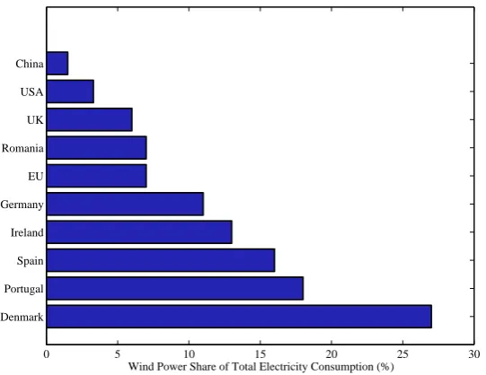
Wind power is rapidly increasing its presence in the power generation mix as one of the most promising renewable power source [3]. For many coun-tries wind power has already become an important electricity source, e.g, Denmark, Portugal, Spain and Germany. The percentage levels of power provided by wind sources (the penetration levels) are 21%, 18%, 16% and 11%, respectively [4]. Moreover, installation of offshore wind power is grow-ing fast durgrow-ing last few years, since there is more constant wind and less space limitation. According to [5, 6, 7], Figures 1.1, 1.2 and 1.3 show global wind power evolution all over the world.
2
2001 2002 2003 2004 2005 2006 2007 2008 2009 2010 2011 2012 0
2000 4000 6000 8000 10000 12000
Wind Power Capacity installed (MW)
[image:33.595.173.439.126.327.2]Onshore Offshore
Figure 1.1: Wind power capability installed in EU
0 5 10 15 20 25 30
Denmark Portugal Spain Ireland Germany EU Romania UK USA China
Wind Power Share of Total Electricity Consumption (%)
Figure 1.2: Wind power share of total electricity consumption
[image:33.595.173.444.367.576.2]3 1. Introduction
0 10 20 30 40 50 60 70 80
China USA Germany Spain India UK Italy France Canada Portugal Rest of the World
Top 10 countries on wind power capacity installed (GW)
Acumulative capacity installed in 2011 New capacity installed in 2012
Figure 1.3: Accumulative wind power capacity per country installed in GW
in the final version of the “ENTSO-E Network Code for Requirements for Grid Connection Applicable to all Generators”, the power system stabilizer capability as a requirement for any generation units (including wind farms) larger than 10 MW (in the case of UK, Baltic countries and Nordic Area) and 50 MW for Continental Europe Area [20].
The stability of power systems is related to the electromechanical inter-actions and the behavior of the generators connected to the grid. There-fore, the influence of wind power penetration on the power system is an important issue to be studied [21]. It is important to analyze wind power behaviour under different wind power technologies and controls, as they present different dynamic characteristics causing different effects on the grid [22, 23]. The contributions to power system oscillations damping have been studied considering different technologies, e.g., HVDC links and their con-trollers [24, 25, 26, 27, 28, 29], by means of flexible AC transmission systems (FACTS) [30, 31, 32] and using wind farms [17].
1.1 Research motivations and objectives
af-1.1. Research motivations and objectives 4
fects power systems behavior since wind technologies, including both asyn-chronous generators and converter-based wind turbines , are reducing power system global inertia [33]; hence, power system dynamics is changing. The dynamic characteristics of wind farms are substantially different from con-ventional power plants. For that reason, TSOs have defined some grid codes regarding wind farm connection, and how wind farms must interact with the electrical network [10, 11, 12]. Nowadays, power system oscillation damping is not a mandatory TSO requirement but there is a draft of the new Spanish grid code for wind power that considers this necessity [19];a requirement that has also been taken into account by ENTSO-E for the European com-mon Grid Code, depending on the power generator unit size (including wind power) [20]. Such new challenge for wind power generation has motivated the core of the work carried out throughout this thesis. The main goals of the present thesis are summarized as follows.
• To understand the impact of each wind turbine technology on the
power system small signal stability; since, they modify the power sys-tem behavior.
• To investigate the possible contribution of wind power plant focusing in variable–speed converter wind turbines (FRCWTs) to damp out power system oscillations.
• To evaluate the influence of different factors related to wind power plants (such as cable length connection) on the contribution provided to power system oscillation damping.
• To compare different controllability/observability and signal interac-tion analyses for power system oscillainterac-tion damping using wind power plants to select the best signal pair.
• To study control design limitations imposed by the impossibility of carrying out direct measurements of the signals selected for control.
• To develop the tools to select effectively the wind power plant local signals to properly damp power system oscillations without the re-quirement of designing the controller.
5 1. Introduction
1.2 Thesis contributions
The main contributions of the thesis are summarized below along with their associated publications:
• To investigate what is the impact of wind turbine technologies on power system stability [J2].
• To implement a power system stabilizer for variable speed wind tur-bines [J3, J5, C2, C5].
• To study and compare the effect of different factors such as refer-ence signals controlled, cable length and wind power plant location, on power oscillation damping contribution from wind power plants
[J5, C5].
• To provide a recommendation guideline to select the best input-output signal pairs for different control schemes to damp power system oscil-lations by means of wind power plants signals, either through single-input single-output (SISO) or multivariable (MIMO) control [J7].
• To put forward input-output signal selection criteria in order to achieve the best possible control response considering the fundamental limita-tions imposed by the use of wind power plant local signals to damp out oscillations at synchronous generators; this criteria is completely independent of the controller [J6].
• To analyze both technical and economic aspects regarding the use of non-standard operating frequency at offshore AC networks [J4].
• To develop frequency dependent cost functions of the electrical com-ponents required for SuperNode concept installation [J4].
The publications indicated above are fully detailed in Appendix A.
1.3 Thesis outline
1.3. Thesis outline 6
In Chapter 2, a brief overview of some power system background required for small signal stability analysis is introduced.
Chapter 3 reviews the influence of wind power generation on small signal stability and provides a review of the different control methods for wind turbines (WT) proposed in literature to damp both inner and power system oscillation modes.
In Chapter 4, a comparison of different PSS controllers from WPPs to damp inter-area oscillation modes with local signals is done; moreover, the influence of the distance from WPP to the main network on the controller and the effect of the WPP location are analyzed.
In the first three chapters, the effect several factors as the controller in-cluded, the signals used as input and outputs of such controller and the power system model, can be observed on the capability of damping oscillations. As a consequence, it is difficult to draw a clear conclusion or recommendation. To circumvent this issue, power oscillation damping is analyzed using tools which are independent from the controller.
In Chapter 5, different input-output selection methods for SISO and fre-quency domain methods for MIMO systems are compared, assuming the possible contribution of WPPs to damp such oscillations in the point of WPP connection.
Chapter 6 proposes a criterion to determine the best input-output local signals of WPP to damp power system oscillations at synchronous generators by considering the fundamental control limitations of the systems.
Chapter 7 differs slightly from the main study objective, since it deals with the analysis of a new offshore wind power plant design considering the economic effect of operate the offshore AC network at non-standard frequencies.
2
Power systems background
An electrical power system can be defined as a set of various individual interconnected electrical elements creating a large, complex and dynamic system which is capable of generating, transmitting and distributing elec-tricity within a large geographical area, required to satisfy elecelec-tricity demand [34]. Such elements interconnection could lead to a large variety of dynamic interactions. Some of those interactions only affect to a few number of the elements, others to a large part of the power system and, also, others could involve the whole system.
This chapter aims to give a general overview of the main concepts and background required to better understanding of the analysis presented through-out this thesis.
This chapter is organized as follows. In Section 2.1, a brief description of the concepts related to power system stability and small signal stability is done. In Section 2.2, a short description of the main elements present in a power system (such as lines, transformers, synchronous generators and wind power plants) is given. Moreover, some modelling assumptions for power system stability analysis are presented. Finally, in Section 2.3, an introduction to the mathematical basis required for small signal stability analysis is presented.
2.1 Power system stability
2.1. Power system stability 8
disturbance [35, 36].
Power system stability can be classified according to the response of the system to a fault [37] (Figure 2.1).
- Rotor angle stability is concerned with the ability of the interconnected synchronous machines of a power system to maintain or restore equi-librium between electromagnetic torque and mechanical torque, and also to keep the synchronization between them.
- Frequency stability can be defined as the capability of a power system to recover the balance between the system generation and the load, with minimum loss of load.
- Voltage stability refers to the capability of a power system to main-tain the steady state of all bus voltages both under normal operating conditions and after a disturbance.
Power System Stability Stability
Frequency Stability
Voltage Stability Rotor Angle
Stability
Small Signal Stability
Transient Stability
Figure 2.1: Classification of the power system stability concepts
Depending on the particular fault, rotor angle stability can be classified in two different groups [35]:
9 2. Power systems background
• Small signal stability or small-disturbance stability considers the abil-ity of the power system to maintain synchronism during small distur-bances. The effect of small disturbances on the variables of the system is considered in small signal stability analysis, and these disturbances are considered small enough to make acceptable the linearization of the non-linear equations of the power system. Small disturbances can be, for example, minor changes in the load or in the generation of the power system.
The study of small signal stability may result in two different response modes
• Non-oscillatory or aperiodic mode due to lack of synchronizing torque. The synchronizing torque is the component of torque change in phase with the rotor angle perturbation. The aperiodic problem has been largely solved by the use of automatic voltage regulators (AVR) in the generators.
• Oscillatory mode due to lack of damping torque. The component of torque in phase with the speed deviation is the damping torque. Os-cillation modes are usually cancelled by means of Power System Sta-bilizers (PSS).
The small-signal modes of oscillation can be classified as [38, 39].
• Power system oscillations
- Inter-area modes. They are oscillation modes occurring
be-tween groups of generators that are far among them. Generators that belong to one area oscillate against other group of gener-ators from other areas. This sort of oscillation appear usually when there is a power transfer between areas that are connected through a tie-line. The frequency range of these oscillation modes are approximately between 0.1 to 0.7 Hz.
- Local modes or Intra-area modes. This kind of oscillation
mode are related with the rotor angle oscillation of a single syn-chronous generator against the rest of power system or the rest of the local area where the generator belongs. The frequencies of such modes are usually in the range of 0.7 to 2 Hz.
2.2. Power system representation 10
- Torsional modes. They are related to the interaction among
the mechanical system of the synchronous generators and some power system elements such as reactive power compensators.
- Control modes. These oscillation modes consider the effect of
various controllers within the power system including excitation control, power converters, etc.
This classification permits to identify the causes of the oscillations and to propose damping control strategies.
The thesis is mainly focused on small signal stability analysis. For that reason, some background material about small signal stability is introduced to ease understanding of the rest of the thesis.
2.2 Power system representation
As previously defined, a power system is understood as a group of different electrical components interconnected among them as shown in Figure 2.2.
Onshore Offshore
Figure 2.2: Representation of a meshed power system with wind power generation
11 2. Power systems background
to the modelling of such components and some simplification assumptions made for the present thesis are given. The combination of these elements provides the power system set of differential and algebraic equations required to develop power system analysis including both dynamic and static.
2.2.1 Lines and cables modelling
Cables and lines are the elements used to transmit and distribute electrical power through various areas. Transmission lines and cables are commonly represented by theirπ-equivalent circuit with lumped parameters, shown in Figure 2.3. Such equivalent provides an approximation of the line (or cable) performance from its terminals [40].
XC
R XL
XC
Figure 2.3: Representation of the transmission lineπ-equivalent
For power system stability analysis, this model may be simplified in a different manner if it is modelling a cable or a line. For the case of lines, they can be only modelled lossless by inductances, neglecting both the resistive and the capacitive effect. Conversely, cables can be modelled as a shunt capacitor [40, 36].
2.2.2 Transformer modelling
Transformers are important component of the power system since they pro-vide the capability of linking different network parts operating at different voltage levels. Moreover, they are capable to control voltage by means of the tap changer. Transformers can be ideally represented by the equivalent cir-cuit shown in Figure 2.4. This circir-cuit can be approximated to an equivalent
π-circuit (similar to the scheme shown in Figure 2.3) after some assumptions are made [34].
2.2. Power system representation 12
R1 XL1
GF e Bµ n1 n2
T1
R2 XL2
Figure 2.4: Representation of the equivalent circuit of a two-winding transformer
2.2.3 Synchronous generator modelling
Synchronous machines are one of the most important elements in a power system, and they have large effect in power system stability [41], even more in electromechanical oscillations. There exist various levels of complexity of synchronous machines dynamic models; but, with exception of very small power systems, complex models of the synchronous machines cannot be used for stability studies [42]. It is worth to remark that high order models used to add only little extra information into power system stability analysis [33]. The simplest synchronous machine representation is the so-called classical model which is used to explain some of power system stability fundamentals. It is described by the swing equation (Newton’s second law for rotating masses),
Md
2δ
dt =Pm−Pe−Dω (2.1)
whereδ,ω,Pm,Pe and Dω represent the rotor angle, the rotating speed of
the rotor, the mechanical power, the electrical active power generated and the damping power of the synchronous generator, respectively.
This equation can be rewritten into a set of differential equations such as,
dδ
dt =ω−ωs dω
dt =
1
M (Pm−Pe−Dω)
(2.2)
where Pe = E0V
X0 sin (δ−θ) assuming the generator as a voltage source, E 0
13 2. Power systems background
Another simplified model used within the thesis for theoretical studies, neglects the effect of the damper windings. This is a third order model of the synchronous machine considering the swing equation and the d-axis electromagnetic field (EMF) transient dynamics. This model represents the synchronous generator as a voltage source behind a transient inductance as shown in Figure 2.5.
E′
X′
Figure 2.5: Representation of a synchronous generator as a voltage source behind a transient inductance
In order to reach such model, some assumptions for the synchronous ma-chine must be taken into account:
• The resistor resistanceRs and stator transients
1
ωs dψ
dt are neglected.
• Thedand q axes donot contain damper windings.
The third order synchronous machine model is given by
˙
δ =ω−ωs,
˙
ω = ωs 2H
Pm− E0V
1
X0 sin(δ−θ)−Dω
,
˙
E0 = 1
T0
Ef − X X0E
0+X−X
0
X0 V cos(δ−θ−Dω)
.
(2.3)
The derivation of the equations can be found in literature, e.g., [42, 33].
2.2.4 Wind power plant
2.2. Power system representation 14
synchronous generators. It means that wind power plants are required to accomplish with TSOs demands, in terms of power generation, control and ancillary services. These requirements can be found in the grid codes de-veloped by national TSOs, e.g., [11, 10]; although at this time, a common European grid code is being prepared by the ENTSO-E [20].
For that reason and the rapid technology development, it is important to know if the sort of wind turbines that are installed would be able to act as a wind power plant. Some of the most common wind turbine generator systems are briefly described in the following. Afterwards, how the wind power plant modelling assumptions for power system stability analysis are introduced.
Common wind turbine technologies
Wind power generation systems is evolving fast; for that reason, different concepts of wind turbine technologies are currently installed all over the world. These wind turbine technologies are usually classified as type A, B, C and D (in United States named type I, II, III, IV, respectively), depending on the capability of frequency regulation of each wind turbine configuration [8, 43, 44, 17]. It is worth to remark that the concepts known as variable speed are (C and D), at the moment, the most popular [45].
Fixed speed wind turbine - Type A Figure 2.6 shows a fixed speed wind turbine. This wind turbine topology is implemented with a squirrel-cage induction generator (SCIG), and is directly connected to the power system through a step-up transformer. A capacitor bank is used to compensate the reactive power requirement of the SCIG. Moreover, induction generators have a critical transient response of the currents during their connection and disconnection, a smoother grid connection is achieved by using a soft-starter. The turbine speed of this type of wind turbine is fixed or nearly fixed (≈ ± 1%) to the electrical frequency of the grid.
Partial variable speed wind turbine - Type B A schematic of Type B wind turbine representing the partial variable speed wind turbine is presented in Figure 2.7. This wind turbine topology encompasses a wound rotor induction generator (WRIG) equipped with a dynamic rotor resistance (DRR). The wind turbine is builded by connecting an external rotor resistance Rext to
15 2. Power systems background
β Gear
Box SCIG Soft Starter
Capacitor Bank
Figure 2.6: Fixed speed wind turbine with squirrel cage induction generator
of reactive power compensation and soft-starter. This type of wind turbines are known as partial variable speed due to they are capable to regulate the rotor resistance increasing the turbine speed range in a moderate manner with a slip range from 2% to 10% (always above rated turbine speed). The excess of power is dumped as heat loss. The regulation of DRR control can help to improve power quality, reduce flicker emission from wind turbines to the power grid, among others [46].
β
Gear
Box
Soft Starter
Capacitor Bank
IG
Figure 2.7: Partial variable speed wind turbine equipped with wound rotor induction generator with dynamic rotor resistance
2.2. Power system representation 16
the nominal power of the generator) which is connected to the rotor circuit. In this wind turbine technology, the generator stator windings are connected directly to the grid through a step-up transformer and the rotor is connected through the power converter which controls the rotor currents and decouple rotor speed from the electrical frequency of the grid. Moreover, this configu-ration does not require neither reactive power compensation nor soft-starter, since such operations are performed by the partial rated converter. Although Type C corresponds to a limited variable speed wind turbine, it is accepted as variable speed since it can be operated in a wider range of dynamic speed which is± 30% approximately.
β Gear Box
DFIG
Partial Power Converter
DC AC
AC DC
Figure 2.8: Variable speed wind turbine driving a doubly-fed induction generator
17 2. Power systems background
β Gear Box
SCIG
Full Rate Converter
DC AC
AC DC
(a) Variable speed wind turbine with full rate converter induction generator
β
SG
Full Rate Converter
DC AC
AC DC
(b) Variable speed wind turbine with direct drive synchronous generator
2.2.5 Wind power plant modelling
2.3. Mathematical basis of small signal stability 18
2.3 Mathematical basis of small signal stability
As previously stated, power systems are usually described by a set of non-linear differential equations together with a set of algebraic equations, i.e.,
˙
x=f(x, u),
y =g(x, u), (2.4)
where x= x1 x2 .. . xn u= u1 u2 .. . um
, y=
y1 y2 .. . yr ,f =
f1(x, u)
f2(x, u)
. . . fn(x, u)
, g=
g1(x, u)
g2(x, u)
.. .
gr(x, u)
where x is the vector of the state variables, u is the vector of the system inputs,y is the vector of the system outputs, andf andg are the vectors of nonlinear functions. Moreover,nis the order of the system,mis the number of inputs considered in the system, and r is the number of outputs.
For a small signal stability analysis, the system (2.4) is linearized around an operating point [34]. Linearization is reasonable because, as previously stated, the disturbances are assumed to be small. Then, the power system can be written as a linear system of the form
∆ ˙x=A∆x+B∆u,
∆y =C∆x+D∆u, (2.5)
where A= ∂f1 ∂x1
. . . ∂f1 ∂xn
..
. . .. ...
∂fn ∂x1
. . . ∂fn ∂xn
, B=
∂f1 ∂u1
. . . ∂f1 ∂um
..
. . .. ...
∂fn ∂u1
. . . ∂fn ∂um , C= ∂g1 ∂x1
. . . ∂g1 ∂xn
..
. . .. ...
∂gr ∂x1
. . . ∂gr ∂xn
, D=
∂g1 ∂u1
. . . ∂g1 ∂um
..
. . .. ...
∂gr ∂u1
. . . ∂gr ∂um
19 2. Power systems background
The linear system presented in (2.5) is represented by the scheme shown in Figure 2.9.
C
A
B
D
y
x
x
u
Figure 2.9: State space block diagram representation
2.3.1 Eigenvalues
The stability of the system (2.5) can be analyzed by computing the eigen-values of the state matrix A. The eigeneigen-values are the roots of the system characteristic equation
det(λI−A) = 0 (2.6)
where det is the determinant. The solutions of the equation (2.6) λi may
be real or complex. The eigenvalues provide dynamic characteristics of the system to small disturbances. Since it can be proved that the response of (2.5) is given by
y =
n
X
i=1
Rieλit. (2.7)
Moreover, according to Lyapunov’s first method, the small signal stability of a nonlinear dynamic system is determined by the location of the roots of the characteristic equation [41]. Each eigenvalue can be expressed as
λi=σi±j·ωi, (2.8)
whereσi and ωi determine the response of the system as follows.
- When σi < 0 for alli, the system is asymptotically stable.
2.3. Mathematical basis of small signal stability 20
- When exist one eigenvalue withσi= 0, the system is marginally stable.
- When at least in one of the eigenvalues, ωi 6= 0, the system has a
oscillatory response.
- When ωi = 0 for all i, the system has a non oscillatory response.
Therefore from the evaluation of the eigenvalues, system stability can be determined and also if the power system may present any type of oscillation, as shown in Figure 2.10. Moreover, the real part σi of the eigenvalue λi
provides the damping of the amplitude of the oscillations; meanwhile, the imaginary partωi indicates the oscillation mode frequency.
−1 −0.5 0 0.5 1
−10 −5 0 5 10
σ
ω
21 2. Power systems background
The damping ratio ξi permits to state how damped are the oscillation
modes, and it is calculated as follows
ξi=
−σi
q
σ2
i +ω2i
= −σi
ωni
, (2.9)
whereωni =
q
σ2
i +ω2i represents the undamped frequency of the mode.
Therefore, eigenvalues with real part close to the right hand plane and smaller damping ratio will be the most important in stability analysis, since they would became unstable easily.
2.3.2 Eigenvectors and participation factor
An eigenvector can be easily understood as a non-null state vector which after being multiplied by the state matrixA, returns a proportional of such vector. The ratio between both vectors is the eigenvalue related to the eigenvector [50]. There is an eigenvector associated to each the eigenvalues. The right eigenvector Φi of the eigenvalue λi must satisfy the following
equation
AΦi =λiΦi; (2.10)
otherwise, the left eigenvector Ψi of the eigenvalueλi must satisfy
ΨiA=λiΨi. (2.11)
Right and left eigenvectors are orthogonal between them. Therefore, they can be normalized in order to ease their understanding, such practice is usual in power system.
ΨiΦi =I; (2.12)
thus, the left eigenvector could be calculated as
Ψi= Φ−1i . (2.13)
The participation factor reveals what state variables are affecting to the desired mode to be damped. The participation factor permits to determine the contribution of each state to a particular eigenvalue. Moreover, the participation factor helps to determine exactly the sort of oscillation mode appearing.
The participation matrix is defined from right and left eigenvectors as follows,
2.3. Mathematical basis of small signal stability 22
where
P =
p11 . . . p1n
..
. . .. ...
pin . . . pnn
, (2.15)
with p1i = Φ1iΨi1 [51]. The participation matrix values are generally
3
Literature review of power
oscillation damping supported
by wind power
3.1 Introduction
Power system small signal stability is mainly related to electromechanical in-teractions between synchronous generators and the electrical network. This effect arise commonly after a system disturbance, and shows the existing inner dynamics of the power system. It is worth to remark that with the introduction of converter-based generation technologies the power system is reducing its global inertia implying lower natural damping. It is important to analyze the effect of different wind power technologies and controls into the power systems, as they present different dynamic characteristics.
This chapter aims to discuss wind power impact on small signal stability and to provide a review of the different control methods for wind turbines (WT) to damp both inner and power system oscillation modes. It is impor-tant in order to understand what can be done from wind turbines.
3.2. The impact of wind farms in power system oscillations 24
3.2 The impact of wind farms in power system
oscillations
In this section, the influence of wind farms on the oscillation damping of power systems is analyzed. In recent years, several researchers have analyzed the effects of oscillatory modes from two different points of view: oscillation modes of wind farms against power systems and inner oscillation modes of wind turbines. Most of the research in the literature considers equivalent models of the wind farms to emulate an aggregated behavior in just one big wind turbine connected to the power system [47]. However, in some cases, this approach is not the most appropriate to reduce the wind farm to one-equivalent machine [48]. For example, to determine the oscillatory behavior of the wind turbine components, it is usually necessary to analyze a single wind turbine against an infinite grid.
3.2.1 Oscillations in power system with wind farms
Wind turbines are generally not synchronously connected to the grid; hence they do not participate in electromechanical oscillations. Wind power itself does not induce new low frequency oscillation modes into power systems be-cause their generator technologies do not engage in power system oscillations [52, 53, 54].
Due to the rapid increment of wind power penetration in power systems, it is important to analyze how this fact could affect the dynamic behavior of the power systems. Several researchers divide this analysis not only by the penetration level, but also by changes in the system, such as the substitution of conventional generators by wind farms or the location of wind farms in different power system buses [17, 55, 56].
Here, in order to study the dynamic effect of main wind turbine technolo-gies on the grid, the study is divided into fixed speed and variable speed wind turbines.
Power system with fixed speed wind turbines
25 3. POD from wind power: A review
better damping contribution on inter-area modes than on local oscillation modes [52, 55, 49, 57, 58, 59].
However, some studies reveal that there are special situations where the impact of FSWT could have a detrimental effect on the oscillatory behavior of the power system, e.g., the full load condition of the wind turbines in a weak grid [55, 57], the penetration level in the power systems [21], the connection strength of the tie lines [60] or the location of the wind farm [59]. Although SCIG is the most common generator in FSWT, there are others, like permanent magnet synchronous generators (PMSG) which may engage in power system oscillations since they are synchronous generators directly connected to the grid like conventional power generators. FSWT-PMSG could have stability problems when a disturbance occurs in the power system [61].
Power system with variable speed wind turbines
Variable speed wind turbines (VSWT) are partially or totally decoupled from the grid by a power converter regulating the power delivered by the WT. As a result, power system oscillations do not affect the wind turbine [21, 62].
Unlike FSWT, the influence of VSWT on power system oscillations does not draw a clear answer. In order to analyze the impact of VSWT on electromechanical oscillations, there are some important factors to be con-sidered including wind turbine technology used, control mode of the VSWT and wind power penetration [63].
VSWT technologies can be divided on doubly fed induction generators (DFIG) and full rate converter wind turbines (FRCWT) as shown in Figure 2.8 to 2.9(b). This classification is used in order to analyze the impact of VSWT technologies on low frequency oscillations.
3.2. Impact of Wind Farms 26
collapse weak interconnection lines [70].
Some results reveal that VSWT-DFIGs are able to interact with the PSS of synchronous machines. These WT can damp initial oscillations of the power systems for small disturbances but may decrease voltage stability under large disturbances, in comparison with other synchronous machines [71].
When comparing control methods in the analysis of the interaction be-tween the VSWT-DFIG and the power system, the conclusions are quite different. WT with power factor control, the oscillation modes could be slightly better damped [53, 72] or have a detrimental effect on the damping [67, 73]. On the other hand, WTs with frequency control help to enhance damping of the oscillatory modes [53, 72]. This is because the rotor oscilla-tions are observable from the grid frequency signal. It should be noted that all previous control methods mentioned do not regulate reactive power.
The effect of an additional voltage control loop to regulate reactive power could be detrimental depending on the particular choice of the control pa-rameter and also on the location on the measurement point [67, 74]. The interaction of the voltage control with the frequency control may achieve a slight improvement according to [72]. In Table 3.1, a summary of the influence of VSWT-DFIG is classified by the control used.
Within FRCWT technologies are Direct Drive Synchronous Generators (DDSG) (Figure 2.9(a)) which is the most common, and Full Rate Con-verter Induction Generators (FRCIG) (Figure 2.9(b)). DDSGs have been categorized by some authors in the same group as DFIGs [21, 55], therefore, they concluded that the impact in power systems oscillations of DDSG is similar to DFIG. Again, conclusions are divergent, for instance, a damping enhancement of the power system oscillations is reported in [58, 76]. On the contrary, the damping could be decreased if a power factor control mode is used [49, 43] or if a voltage control is introduced to regulate the reactive power [77].
In contrast, with FRCIGs, the damping of the inter-area oscillation is increased either by power factor control [78] or by voltage control [79].
There is alternatively variable speed wind turbine technology connecting a synchronous generator directly to the grid with a hydro-dynamically con-trolled gearbox [80]. In this technology, wind power penetration could be relevant, since it is a synchronous machine connected to the grid and thus is able to engage with power system oscillations.
27 3. POD from wind power: A review
Control Influence
Power Factor - Small enhancement of the
power system damping [53, 72]
- Some negative effects on the damping of power system os-cillations are reported in [67, 73]
Voltage control - Optimization of voltage con-trol constants with power os-cillation constraints improves the damping [75]
- Sensibility to the control parameters, incorrect values may be detrimental to the damping [67, 74]
Frequency control - Enhance the damping of the power system oscillations [53, 72]
Table 3.1: Summary of results on the impact of the DFIG controls on power system oscillations
3.2.2 Inherent oscillations of wind turbines
In WTs there are several rotating elements and electrical devices interacting. Hence, it is interesting to investigate the oscillations that could appear in the machine or in the wind farm. A wind turbine has many inner oscillation modes, e.g., for-after tower movements. From an electrical point of view, only the torsional modes are important since they are the only ones that may affect the power system. Again, this study is divided in FSWT and VSWT.
Fixed speed wind turbines
3.2. Impact of Wind Farms 28
Technology Influence
FSWT-SCIG - Can improve damping of the
power system [52, 55, 49, 58, 59]
- Can deteriorate oscillatory behavior under special condi-tions [52, 57, 59, 60]
FSWT-PMSG - Has problems in stability [61]
VSWT-DFIG - Can enhance power system
damping [17, 52, 53, 56, 59, 64, 65, 66, 67, 72, 75]
- Can decrease the damping of inter-area oscillations modes [49, 67, 68, 69, 70, 73, 74]
VSWT-DDSG - Can improve oscillatory
be-havior of the power system [58, 76]
- Can affect negatively in os-cillations [49, 43, 77]
VSWT-FRCIG - Can affect positively in
power system oscillations [78, 79]
Table 3.2: Summary of results on the influence of wind power technology on power system oscillations
shaft models cannot properly represent mechanical oscillations.
Mechanical oscillations are critical since they induce fatigue stresses on the drive-train components, increasing the risk of damage to the mechanical system. Drive-train oscillation modes are dynamically dominant in the WT. These oscillation modes depend on the shaft stiffness, the network reactance, the rotor resistance and the operating slip.
reso-29 3. POD from wind power: A review
nance phenomena at special gear ratios [84]. Moreover, an electrical distur-bance close to the common coupling point (CCP) may provoke mechanical stresses [85, 86]. Also, the torsional oscillations can be excited by the aero-dynamics of the wind turbine [87]. Even, wind fluctuation in an specific speeds can cause drive-train oscillations to the wind turbine [88].
Variable speed wind turbines
In VSWT, besides of the shaft, the power converter can also affect the inner oscillations. However, it can be noticed that the inherent oscillations of the machines does not dependent on VSWT technologies. These oscillations are mainly associated with the drive-train and with the converter [67, 76, 89].
In VSWT operating at constant generator torque, there is a slight damping provided by the induction generator in comparison with FSWT since the torque does not vary with the generator speed [17, 83]. This fact implies that torsional oscillation modes in VSWT are less damped than in FSWT.
The interaction between these inner oscillations and different converter controls is interesting to analyze. Voltage control could present a poorly damped shaft oscillation mode for certain parameter setting [90]. Incorrect controller constants may cause an amplification of the oscillations during a fault in the CCP. Analyzing this control configuration in more detail, a range of controllability and stability can be determined [91]. In [92, 93], a study of the sensibility of the oscillation modes to different parameters is presented, e.g., wind speed and mechanical torque input, and the critical stability points, known as Hopf Bifurcation, are determined.
In [94], the behavior of different power control strategies, as in maximal power point tracking (MPPT) and power smoothing have been analyzed. The first control has a positive effect on the oscillation damping of the gen-erator, whereas power smoothing control has no damping effect.
A scheme giving an overview of the key points of the impact of wind farms on power system oscillations is shown in Figure 3.1.
3.3 Damping control for wind turbine inner oscillations
3.3. Mechanical damping control 30
Wind Power Impact on
Oscillations Oscillations
FSWT VSWT
Inner:
‐Drive‐train Oscillations
Inner:
‐Drive‐train Oscillations
‐Converter Oscillations
PMSG
SCIG PMSG DFIG FRCWT
SCIG DFIG FRCWT
It has good influence on Stability problems.
It engages in power
Its influence depends
on the implemented
It does not show any
particular behaviour
i t
damping of oscillations systemIt engages oscillations in power oncontrol the implemented schemes in power system
oscillation
Figure 3.1: Brief summary of the impact of Wind Farms on oscillations
3.3.1 Mechanical regulation
Inner oscillation modes of the wind turbine can be mechanically damped by regulation of the blades using the pitch control, by the inclusion of me-chanical dampers in the wind turbine drive-train or by the inclusion of some external devices such as FACTS.
Generally, the mechanical stress suffered by the wind turbine (for instance torsional oscillation) is generated by a difference between the turbine and the generator torque. This difference could be produced by several causes, such as an electrical fault close to the wind turbine or wind gusts. This torsional oscillation could be smoothed by pitch angle control which reduces the torque in the turbine [95, 96, 97].
Direct-drive wind generators which directly couple the generator to the wind turbine, eliminate the requirement of a gearbox. However, they make the conventional generator design of the windings ineffective to damp os-cillations, requiring a damper in the wind turbine [98]. In this paper, a spring and a mechanical damper are included to enhance the damping of the mechanical oscillations.