Robot Arm Fuzzy Control by a Neuro-Genetic
Algorithm
Carlos Kavka, Mara Liz Crespo
Proyecto UNSL 338403
Departamento de Informatica
Universidad Nacional de San Luis
Ejercito de los Andes 950, 5700, San Luis, Argentina
E-mail:
fckavka,mcrespo
g@unsl.edu.ar
Abstract
Robot arm control is a dicult problem. Fuzzy controllers have been applied succesfully to this control task. However, the denition of the rule base and the membership functions is itself a big problem. In this paper, an extension of a previously proposed algorithm based on neuro-genetic techniques is introduced and evaluated in a robot arm control problem.
The extended algorithm can be used to generate a complete fuzzy rule base from scratch, and to dene the number and shape of the membership functions of the output variables. However, in most con-trol tasks, there are some rules and some membership functions that are obvious and can be dened manually. The algorithm can be used to extend this minimal set of fuzzy rules and membership functions, by adding new rules and new membership functions as needed.
A neural network based algorithm can then be used to enhance the quality of the fuzzy controllers, by ne tuning the membership functions.
The approach was evaluated in control tasks by using a robot emu-lator of a Philips Puma like robot called OSCAR. The fuzzy controllers generated showed to be very eective to control the arm.
A complete graphical development system, together with the emu-lator and examples is available in Internet.
Keywords: robot arm control, fuzzy controllers, neural networks,
evolu-tionary algorithms.
The research group is supported by the UNSL and the ANPCYT (Agencia Nacional
1 Robot emulator
The robot emulator selected was Simderella, developed by Patrick van der Smagt at the University of Amsterdam in the Netherlands [11]. This system emulates a Philips PUMA like robot called OSCAR with three rotational joints. A diagram is presented in gure 1. The joint 3 is coupled with the joint 2, providing the eect that when the joint 2 is moved, the joint 3 is moved automatically in the opposite direction, in such a way that the angle of the third link of the arm and the base remain constant.
joint 1 joint 2
joint 3
link 1
link 2
link 3
camera
Figure 1: A diagram of OSCAR
The robot arm has a camera located in the end eector (hand) that provides the distances to the target object in all x, y and z coordinates.
Distances can be positive or negative depending on the position of the hand relative to the target object.
The emulator provides commands to reset the arm to a default position, to move the arm by providing the osets to apply to the joints, and to read the distances to the target object.
2 Control Problem
The control task can be specied as follows: given a random starting position for the arm and a random position for the target object, move the arm to reach the target object.
The camera located in the hand of the robot provides the distance to the target object at any time. The goal state is such that the distance in thex direction is 0, the distance in the y direction is 0 and the distance in
The objective is to build a controller that can provide the osets to apply successively to the joints 1 and 2 to move the arm to reach the target object. The controller should have three inputs and two outputs. The three inputs are the distance in the x direction to the target object, the distance in the y direction and the distance in the z direction. The outputs are the osets
to apply to the joints 1 and 2. A diagram is presented in gure 2.
CONTROLLER
offset joint 2 distance x
distance y distance z
offset joint 1
Figure 2: Controller
The space in which the robot operates is specied as a standard three dimensional space with three coordinates corresponding to the axisx,y and z. The joint 1 is always located at the origin. The robot arm cannot go
below the oor soz values are always positive. We restrict the x values to
be positive. The resulting range forx is 0..100, fory is -100..100 and for z
0..100.
The target object is located in random positions in the space, but avoid-ing positions in which the arm cannot reach it. The distances obtained by the camera can be in the range -100..100 forx, -200..200 fory and -100..100
forz. Figure 3 presents some examples.
z
x y
z
x y
Figure 3: Some examples: The robot arms shown here have the hands in (70,0,70) and (55,60,65) respectively, the target objects are in (55,60,65) and (0,-60,40) respectively and the distances from the hands to the target objects are (15,60,5) and (125.64,-40.54,25) respectively.
3 Fuzzy Control
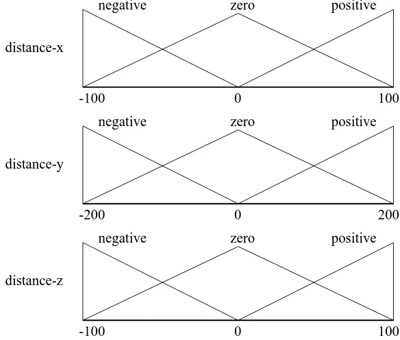
The rst step in the denition of a fuzzy controller is the selection of the fuzzy membership functions for the input variables. We propose to chose a standard partition with the three fuzzy setsnegative,zero and positive for
each input variable, as it is show in gure 4.
0 zero
negative positive
distance-x
-100 0 100
zero
negative positive
distance-z
-100 0 100
zero
negative positive
distance-y
-200 200
Figure 4: Fuzzy sets for the three input variables
The selection of the fuzzy membership functions for the output variables and the rule base construction is a more dicult problem. Even if we select a standard partition of seven fuzzy sets for each output variable, the deni-tion of the rules to consider which acdeni-tion should be taken for both output variables in all possible combination of inputs is quite dicult.
The algorithm that we propose here, allows to generate automatically the output fuzzy sets and the rule base.
4 Symbiotic Evolution
In a previous work, we have proposed to use symbiotic evolution to evolve neural networks that represents fuzzy systems [13]. The advantage to evolve neural networks is that at the end, we obtain a fuzzy controller that can be enhanced by traditional neural network methods.
[image:4.612.150.442.168.416.2]evalu-ated on an independent basis. The population converges to the dominant structure. This convergence is desirable if it goes into the global optimum, however, usually it converges into a local optimum.
When the population has converged prematurely, the genetic algorithm does a linear search in the solution space by just doing mutations, instead of doing an ecient parallel search.
The basic idea of the symbiotic evolution is that the individuals of the population will represent partial solutions. The goal of each individual is to be an adequate partial solution to be combined with other individuals of the population. As each individual is not a solution by itself, and as it must rely on others to reach a high tness value, it must maintain a symbiotic relation.
Each partial solution must be specialized in one aspect of the problem, so in this way, it is impossible to have a premature convergence of the population. The population remains diverse.
The SANE (Symbiotic Adaptive Neuro Evolution) algorithm was pro-posed by Miikkulainen and Moriarty [1] [2]. The novel approach of SANE, is that it encodes one unit of a neural network as one string (chromosome). The tness of a unit is determined by its degree of cooperation with the other units used to form the network. SANE keeps a population of units that represents the hidden units in a standard feed-forward neural network. The input and output units are determined by the problem itself.
SANE is very good in doing a quick eective search of the solution space, but it becomes very dicult for it to reach the best solution.
HSANE (Hierarchical SANE) is proposed by the same authors and over-comes this diculty. It combines the advantages of the network level evolu-tion with the advantages of the unit level evoluevolu-tion. HSANE keeps two dif-ferent populations, one for the units, and another one fornetworkblueprints.
The population of units evolve into good units, and the population of net-works into good combinations of units.
5 Representation of fuzzy systems as neural
net-works
A fuzzy system can be represented as a ve layers GARIC-like neural net-work [5]. For example, a simple fuzzy system with two input variables with three fuzzy sets each one, two output variables with two fuzzy sets each one, and ve rules, can be represented as it is shown in gure 5.
L1
M1
R3 R2 R1
I2 I1
H1
L2
M2
H2
R4
R5
A1
A
B1
B2
B A2
Figure 5: Fuzzy system as a GARIC-like neural network
Just as an example, the rule 2 represented by the neural network in the gure 5 is:
if I1 is L1 and I2 is H2 then A is A1 and B is B1.
6 Codication
A new codication should be dened to apply HSANE to the domain of the fuzzy neural networks that represents fuzzy systems with more than one output variable. Note that with a symbiotic approach, one string will not represent a complete neural network.
The layer one, two and ve are not included in the codication because they are xed. Only the layers three and four, and the connection pattern will be codied into the strings. One string will represent one unit for each output variable of the fourth layer with all the units in the layer three to which they are connected, and all the connections between them.
The following parameters are dened:
N: this is the number of chromosomes used to form a network and it
will determine the size of the fuzzy system obtained.
OV: this is the number of output variables and it is xed depending
on the problem. In the case of the robot control it will be 2.
IV: This is the number of input variables and it is also xed depending
on the problem. In the case of the robot control it will be 3.
NR: This is the maximum number of rules that can use one particular
this limit and it will not generate more rules with the same conse-quent. This is particularly important when the fuzzy system will be implemented in hardware, where this restrictions apply.
The gure 6 shows two strings that codify the network from gure 5.
OV NR
0
0.00 0.16 0.36 0
0.13 0.31 0.80
0.70 0.53 0.18
0.25 0.60 0.55
3 2
91 188 155 201 2 221
11 230
no rule rule 5 rule 3 rule 2
rule 4 fuzzy set A2
fuzzy set A1 fuzzy set B1
fuzzy set B2
rule 1
IV
Figure 6: Strings that codify the network from gure 5
A string consists of a series of elds. It starts withOV groups of three
elds. These three rst elds (16 bits values) will codify three oating point numbers in the range 0...1, that represent respectively the center, left spread and right spread of the fuzzy set dened by a fourth layer unit (output fuzzy set). In this way, one output fuzzy set for each output variable will be codied at the beginning of the string.
Following them, a series ofNR groups ofIV 8 bits elds will codify how
the connections must be done to the units in layer three. Let
k
i(i
= 1;:::;n
)be the number of fuzzy sets for the input variablei. If the valued of a eld
is smaller than or equal to 127, then
d modulo
(k
i) is the index of the inputfuzzy set of the variable i. This means that this particular fuzzy set is an
antecedent of the rule node under consideration. If the value d is bigger
than 127, then no connection is made to this input variable. It is assumed that the input fuzzy sets for each variable are numbered starting from zero. The output fuzzy sets codied by these strings are shown in gure 7. The areas of the fuzzy sets that are outside the range 0...1 are not considered at all.
7 Learning strategy
0 1
0 1
A1
B2 B1
A2
A
B
Figure 7: Output fuzzy sets codied by the strings from gure 6 Each system is evaluated in 100 time steps, always starting from the rest position with the hand in (85,0,65). Four dierent test cases are considered with the target object in (70,60,55), (55,45,75), (70,-60,55) and (55,-45,75). Only four cases are enough, because they include all possible movements for the arm. They include cases to move the arm in the right-down direction, in the left-down direction, in the left-up and in the right-up direction.
The fuzzy controller obtained should be able to reach a target object located in any position starting from any position, even if it was generated by just considering these four cases. The reason is that the controller does not know anything at all about absolute coordinates. It only considers distances and osets.
An incremental learning strategy is proposed to obtain controllers that can to reach the target object as fast as possible. The arm is allowed to be at least at 50% of the maximum distance at 50 time steps and at least at 25% of the maximum distance from the moment in which the 75 time steps are reached. If it fails to fulll these requirements the evaluation process for the current test case is abandoned.
The tness function is dened in such a way that controllers that can reach the target object receives higher score the controllers that fail to reach it.
tness(system) = 4 X
k=1
(maxX x t)
2
(maxY y t)
2
(maxZ z t)
2
parameter value low level population size 800 high level population size 100 fuzzy sets per output variable 7 maximum number of rules per fuzzy set 2 low level individuals for crossover 150 high level individuals for crossover 30
mutation rate 0.1
Table 1: Parameters for the evolutionary algorithm
The parameters of the evolutionary algorithm are dened as it is shown in table 1.
8 Experimental results
All runs of the evolutionary process were successful, it means that in every execution of the evolutionary process, a successful controller is obtained. The results presented here corresponds to one example of these runs.
Figure 8 shows the evolution of the tness against the number of gener-ations.
4000 4200 4400 4600 4800 5000 5200 5400 5600 5800 6000
0 5 10 15 20 25 30
fitness
generations
"fitness"
Figure 8: Fitness evolution
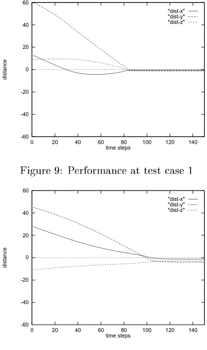
Figure 9 to gure 12 shows the plot of the distances when the fuzzy controller obtained in generation 15 is evaluated on the four cases used for learning. The performance is adequate as expected.
-60 -40 -20 0 20 40 60
0 20 40 60 80 100 120 140
distance
time steps
"dist-x" "dist-y" "dist-z"
Figure 9: Performance at test case 1
-60 -40 -20 0 20 40 60
0 20 40 60 80 100 120 140
distance
time steps
"dist-x" "dist-y" "dist-z"
Figure 10: Performance at test case 2
-60 -40 -20 0 20 40 60
0 20 40 60 80 100 120 140
distance
time steps
"dist-x" "dist-y" "dist-z"
[image:10.612.190.398.77.428.2]-60 -40 -20 0 20 40 60
0 20 40 60 80 100 120 140
distance
time steps
"dist-x" "dist-y" "dist-z"
Figure 12: Performance at test case 4 variable set center left spread right spread
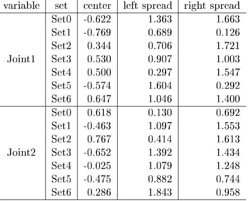
Set0 -0.622 1.363 1.663 Set1 -0.769 0.689 0.126 Set2 0.344 0.706 1.721 Joint1 Set3 0.530 0.907 1.003 Set4 0.500 0.297 1.547 Set5 -0.574 1.604 0.292 Set6 0.647 1.046 1.400 Set0 0.618 0.130 0.692 Set1 -0.463 1.097 1.553 Set2 0.767 0.414 1.613 Joint2 Set3 -0.652 1.392 1.434 Set4 -0.025 1.079 1.248 Set5 -0.475 0.882 0.744 Set6 0.286 1.843 0.958 Table 2: Fuzzy sets produced by the algorithm
The algorithm produced 14 rules. They are presented in table 3. The rules may seem strange, but this is the usual aspect of rules when they are generated through an automatic procedure.
The generated fuzzy controller has also a good performance starting from dierent random positions, and reaching objects located in dierent random positions. Some examples are shown in gure 13 to gure 15.
9 The FC-DT system
[image:11.612.173.426.266.471.2]graph-If dist-y is positive then Joint1 is Set6 and Joint2 is Set6.
If dist-x is positive and dist-z is negative then Joint1 is Set6 and Joint2 is Set6. If dist-y is negative then Joint1 is Set5 and Joint2 is Set5.
If dist-x is positive then Joint1 is Set5 and Joint2 is Set5. If dist-z is positive then Joint1 is Set4 and Joint2 is Set4. If dist-y is positive then Joint1 is Set4 and Joint2 is Set4. If dist-z is negative then Joint1 is Set3 and Joint2 is Set3. If dist-z is negative then Joint1 is Set3 and Joint2 is Set3.
If dist-y is positive and dist-z is negative then Joint1 is Set2 and Joint2 is Set2. If dist-x is negative and dist-y is positive then Joint1 is Set2 and Joint2 is Set2. If dist-x is zero and dist-y is negative then Joint1 is Set1 and Joint2 is Set1. If dist-y is positive and dist-z is positive then Joint1 is Set1 and Joint2 is Set2. If dist-y is negative then Joint1 is Set0 and Joint2 is Set0.
if dist-x is negative then Joint1 is Set0 and Joint2 is Set0. Table 3: Fuzzy rules produced by the algorithm
-60 -40 -20 0 20 40 60
0 20 40 60 80 100 120 140 160 180 200
distance
time steps
"dist-x" "dist-y" "dist-z"
Figure 13: Performance at new case with starting position at (95,25,35) and target position at (80,-45,60)
ical tool that allows the denition and graphical edition of complete fuzzy controllers. Includes the possibility to enhance fuzzy controllers by neural network algorithms and now, to generate rules and fuzzy membership func-tions for systems with more than one output variable. The fuzzy controllers can also be enhanced by manual edition.
By using the environment introduced by FC-DT, some rules and some membership functions for the output variables can be dened before. For example, it is very easy to imagine that a kind of zero fuzzy membership
functions will be useful for any controller. Some rules for making no move-ments when the distances arezero could be convenient also. The
-60 -40 -20 0 20 40 60
0 20 40 60 80 100 120 140 160 180 200
distance
time steps
"dist-x" "dist-y" "dist-z"
Figure 14: Performance at new case with starting position at (73,-30,75) and target position at (100,5,45)
-60 -40 -20 0 20 40 60
0 20 40 60 80 100 120 140 160 180 200
distance
time steps
"dist-x" "dist-y" "dist-z"
Figure 15: Performance at new case with starting position at (45,-55,75) and target position at (75,-55,60)
fuzzy sets dened previously. This inclusion of obvious rules and obvious membership functions saves a lot of learning time.
An inverted pendulum system, and now also a robot arm emulator has been included in the distribution. The system and on-line documentation is available in the home web page of FC-DT, at http://www-pr.unsl.edu.ar/ projects/fc-dt. The reader can reproduce the results shown here just by running the system, and of course, can experiment with new problems.
10 Conclusions
controllers in every run. The quality of the obtained fuzzy controllers can still be enhanced by running the neural network based algorithm that was proposed in previous works [12] [13].
The incremental learning strategy allows to reduce the learning time, because systems that fail to go in the right direction from the beginning, are discarded as soon as they fail to fulll the requirements.
The codication proposed is general and can be applied to other prob-lems as well.
The system is freely available allowing other members of the research community to experiment with it.
References
[1] D. E. Moriarty and R. Miikkulainen (1996). Ecient Reinforcement Learning through Symbiotic Evolution. Machine Learning, 22:11-32. [2] D. E. Moriarty and R. Miikkulainen (1996). Hierarchical Evolution of
Neural Networks. Technical Report AI96-242. Department of Computer Sciences, The University of Texas at Austin.
[3] D. D. Leitch (1995). A New Genetic Algorithm for the Evolution of Fuzzy Systems. PhD Thesis. Department of Engineer Science, Univer-sity of Oxford.
[4] A. G. Barto, R. S. Sutton and C. W. Anderson (1983). Neuronlike adap-tive elements that can solve dicult learning control problems. IEEE Transactions on Systems, Man, and Cybernetics, SMC-13:834-846. [5] H. R. Berenji and P. Khedkar (1992). Learning and Tuning Fuzzy
Logic Controllers Through Reinforcements. IEEE Transactions on Neu-ral Networks, vol. 3, no. 5.
[6] C. L. Karr (1991). Design of a Cart-Pole balancing Fuzzy Logic Con-troller using a Genetic Algorithm. SPIE Conf. on Applications of Arti-cial Intelligence, WA.
[7] M. A. Lee and H. Takagi (1993). Neural Networks and Genetic Algo-rithms Approaches to Auto-Design a Fuzzy System. FLAI'93. Springer Verlag, Berlin.
[8] D. E. Goldberg. Genetic Algorithms in Search, Optimization and Ma-chine learning. Reading, MA, Addison Wesley.
[10] S. Nol, D. Floreano, O. Miglino and F. Mondada (1994). How to evolve autonomous robots: Dierent approaches in evolutionary robotics. Ar-ticial life IV. Cambridge, MA.
[11] P. van der Smagt (1994). Simderella: a robot simulator for neuro-controller design. Neurocomputing. Vol. 6 No. 2. Elsevier Science Pub-lishers.
[12] Carlos Kavka, Mara Liz Crespo and Marcelo Cena (1997). Deni-tion of load balancing algorithms in distributed systems through neuro-fuzzy systems. Second International Symposium on Soft Computing SOCO'97, N^mes, France.