Warranty of Quality
ED Corporation
guarantees the quality of this product.Matters on Warranty of Quality
Warranty ConditionsThe warranty term for this product is 2 years beginning on the date of purchase. If there arise defects or abnormalities from this product during the specified warranty term, you can be serviced by the Customer Support Center of ED Corporation, free of charge.
Customer's Burden of Expenses
Customer shall cover expenses at a minimum charge in the case of the following cases.
1) When the warranty term has expired
※ However, this condition is limited to 5 years after the expiry of the warranty term.
2) When the defect is caused by customer's fault or natural disasters ※ Please be noted that this article shall be applied even during
the warranty term. Limited Warranty
If a customer has arbitrarily disassembled or remodeled this product, we do not have responsibility for the warranty.
Service Guide
For a service application or consultation, please contact Customer Support Center, whose phone number is (031)730-7373 and FAX is (031)730-7317.
※ For safe and correct use of this product, be sure to read this manual before use, and operate the product according to the appropriate handling and operating procedures.
Notice of Change
CONTENTS
◁ 1 ▷
PART Ⅰ
▖
·
·
·
·
·
·
·
·
·
·
·
·
·
·
·
·
·
·
·
·
·
·
·
·
·
·
·
·
·
·
·
·
·
·
·
·
·
·
·
·
·
·
·
·
·
·
·
·
·
·
·
·
·
Introduction to Product 1-1. Overview ···91-2. Cautions ···10
1-3. Checking Constituents ···10
1-4. Constitution of Product ···12
1-4-1. Vertical Articulated Robot (ED-7255) ···12
1-4-2. Robot Controller ···13
1-4-3. Teaching Pendant ···15
1-5. Specifications ···17
1-5-1. Robot Body (ED-7255) ···17
1-5-2. Robot Controller ···17
1-6. Installation ···18
PART Ⅱ
▖
·
·
·
·
·
·
·
·
·
·
·
·
·
·
·
·
·
·
·
·
·
·
·
·
·
·
·
·
·
·
·
·
·
·
·
·
·
·
·
·
·
·
·
·
·
·
·
·
·
·
·
·
·
·
·
·
·
·
·
·
·
Teaching Pendant 2-1. Overview ···232-1-1. Operation Mode ···23
2-1-2. Key Function ···24
2-1-3. Menu Manipulation ···26
2-1-4. Program ···26
2-2. Use of Teaching Pendant ···27
2-2-1. Main Menu Screen ···27
2-2-2. AUTO_RUN_MODE Menu ···28
2-2-3. TEACHEDIT_MODE Menu ···30
◁ 2 ▷
PART Ⅲ
▖
·
·
·
·
·
·
·
·
·
·
·
·
·
·
·
·
·
·
·
·
·
·
·
·
·
·
·
ED-IRS (ED-Industrial Robot Simulator) 3-1. Program Installation ···493-1-1. Install ···49
3-1-2. Uninstall ···52
3-2. Screen Configuration ···52
3-2-1. Menus ···52
3-2-2. Docking View ···52
3-2-3. Program View ···54
3-2-4. Arm View ···55
3-3. Menus ···55
3-3-1. File Menu ···55
3-3-2. Edit ···57
3-3-3. View ···62
3-3-4. Connect ···71
3-3-5. Debug ···72
3-3-6. Window ···75
3-3-7. Help ···76
PART Ⅳ
▖
·
·
·
·
·
·
·
·
·
·
·
·
·
·
·
·
·
·
·
·
·
·
·
·
·
·
·
·
·
·
·
·
·
·
·
·
·
·
·
·
·
·
·
·
·
·
·
·
·
·
·
·
Control Program Syntax 4-1. Declaration Statement ···794-2. Control Statement ···85
4-3. Robot Command Statement ···91
4-4. Kinds of Functions and Operators ···102
CONTENTS
◁ 3 ▷
PART Ⅵ
▖
·
·
·
·
·
·
·
·
·
·
·
·
·
·
·
·
·
·
·
·
·
·
·
·
·
·
·
·
·
·
·
·
·
·
·
·
·
·
·
·
·
·
·
·
·
·
·
·
·
·
·
·
·
·
·
·
·
·
·
·
·
·
·
·
·
·
·
·
·
·
MaintenancePART Ⅶ
▖
·
·
·
·
·
·
·
·
·
·
·
·
·
·
·
·
·
·
·
·
·
·
·
·
·
·
·
·
·
·
·
·
·
·
·
·
·
·
·
·
·
·
·
·
·
·
·
·
·
·
·
·
·
·
·
·
·
·
·
Host Command Set
PART
1
Introduction to Product
1-1. Overview
1-2. Cautions
1-3. Checking Constituents
1-4. Constitution of Product
1-5. Specifications
PART 1 Introduction to Product
◁ 5 ▷
PART 1
Introduction to Product
1-1. Overview
A robot system used for real industrial entities is composed of a mechanical arm, a computer-based controller, an end-of-arm tooling, and a teaching pendant. This equipment is made as an education-dedicated system which includes all the elements of a real industrial robot system, i.e., a robot main body, a robot controller, a gripper, a teaching pendant, a program editing software, as shown in Figure 1-1.
In addition, a robot can be controlled by a teaching pendant or ED-IRS control program and simulator so that a user can personally control the robot. This is an experiment and practice device for a robot arm repeatedly movable by the program.
Teaching Pendant
Gripper Robot Arm Robot
Controller
ED-7255 Vertical Multi-Joint Robot
◁ 6 ▷
1-2. Cautions
1) Before using this equipment, read this manual and be sure to check the operation procedures and power voltage to be supplied to it.
2) Before powering on the equipment, check whether there are mechanical interferences or the foreign substances are jammed in gears. If there is any foreign substance, remove it.
3) Remove the objects located within the moving radius of a robot. 4) Do not operate DC motors for each joint with a black cap opened. 5) Be sure to check the voltage of a power source before connecting it
to the equipment.
6) Avoid using this equipment in a humid place.
1-3. Checking Constituents
Please confirm that the following constituents are all included in the package when you unpack the product.
1) ED-7255 (ARM Robot) 2) Controller
3) Teaching Pendant 4) ED-IRS(Install CD) 5) Cross Cable
6) 9 Pin RS-232 7) Encode Cable
8) 25 Pin Motor Power Cable 9) Ex-Motor Cable 2 pieces 10) Storage Vinyl Bag 11) 220V Power Cord 12) User Manual
PART 1 Introduction to Product
◁ 7 ▷
시뮬레이터: Simulator, 제어 라이브러리: Control Library, 수직 다관절 로봇: Vertical Multi-Joint Robot
To install ED-IRS in a PC, the following system environment is required.
- O.S. : Windows XP or higher - Memory : 516MB or more - HDD : 100MB or more
- If there is any missing or damaged one of the above components, please
contact ED Corporation.
- Version of the supplied program is subject to change for improvement of
ED-7255 Vertical Multi-Joint Robot
◁ 8 ▷
1-4. Constitution of Product
1-4-1. Articulated or Multi-Joint Robot (ED-7255)
팔꿈치: Elbow, 손목 (피치+회전): Wrist (Pitch & Roll), 어깨: Shoulder, 그리퍼:
PART 1 Introduction to Product
◁ 9 ▷
This robot has 5 axes for a base, shoulder, elbow, wrist pitch, and wrist roll, all of which are driven by DC motors. To the wrist, a DC motor-driven gripper is attached.
The 6 DC motors respectively have a reduction gear and an encoder which is attached to a real axis. The reduction gear reduces the rotating speed of a motor to operate a robot. The encoder detects the rotating speed of an axis and the right and left rotation directions. In addition, using Absolute Encoder, the rotating angle can be sufficiently limited by means of software limiting, even though there is not a limit switch.
Primary electrical components of a robot body are as follows.
• DC Motor: 5 axes and fingers can move right and left, up and down according to the rotation direction of DC motors. The rotation direction of a DC motor varies as being supplied positive or negative voltage from a controller. Additionally,
ED-7255 Vertical Multi-Joint Robot
◁ 10 ▷
each of the 5 axes and the gripper respectively include an absolute encoder therein.
• Encoder : Encoders employed to the 6 motors continuously detect the position of each joint, rotation direction, and rotating speed of a robot arm.
PART 1 Introduction to Product
ED-7255 Vertical Multi-Joint Robot
◁ 12 ▷
3) Cable
A control box is connected with ED-7255 through a DC motor parallel cable and an encoder parallel cable. A teaching pendant and a control box are connected by RS-232 cable, and PC and a control box are connected by Ethernet cable.
1-4-2. Robot Controller
PART 1 Introduction to Product
◁ 13 ▷
① Power Switch : Turn on/off a main power source. A state LED lights up after main board booting is completed.
② Main Power : Supply DC 220V power source.
③ Motor Port: A parallel port for supplying a motor of each joint with power.
④ Encoder Port: A serial port for reading encoder values of each joint.
⑤ Ethernet Port: Used for downloading commands, reading the robot status, operating a control library command, etc.
⑥ USB Port: For USB interface. Service is expected.
⑦ Connected to PC through a 9 pin cable to perform a serial communication, and is used for operation of a control library through ARM code.
⑧ EM Button: In an emergency situation, pushing EM button stops the system.
ED-7255 Vertical Multi-Joint Robot
◁ 14 ▷
No. Name No. Name
1 CPU(S3C6410) 7 JTAG
2 mDDR SDRAM 8 Ethernet(CS8900)
3 NOR Flash 9 Reset Switch
4 NAND Flash 10 USB (OTG2.0)
5 SRAM 11 Dip Switch (Bootloader)
6 JTAG Connector
⑩ LCD : The status and the current operation state of a robot is
displayed on LCD window.
⑪ Pendant Connector : Connected to a teaching pendant through a
9-pin cable to perform a serial communication.
⑫ Extra Motor Ports: Two extra motor ports are provided for control of peripheral devices.
1
2
3
4
8
6
7
10
9
PART 1 Introduction to Product
◁ 15 ▷
ED-7255 Vertical Multi-Joint Robot
◁ 16 ▷
수량: Q'ty
By using input points, interfacing with external I/O devices or sensors becomes possible. These input points provide a power terminal of 5A, 24V DC to supply the external I/O devices or sensors with the power source.
PART 1 Introduction to Product
◁ 17 ▷
내부회로: Internal Circuit, 출력점: Output Point, 입력점: Input Point
1-4-3. Teaching Pendant
ED-7255 Vertical Multi-Joint Robot
◁ 18 ▷
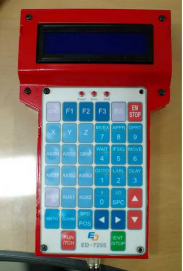
Figure 1-28 shows a teaching pendant, which is composed of a key pad, LCD window, an emergency stop key, and a connection connector.
PART 1 Introduction to Product
◁ 19 ▷
The teaching pendant has the following 5 operation modes.
① PLAY Mode : Move a motor. Set an output point. Check an input point.
② EDIT Mode : Identical to the PLAY mode, except a function that commands are stored in a file. Program control commands including conditional or non-conditional branch can be stored. The program file can be displayed, modified, and executed in sequence.
③ RUN Mode : Program files are executed. The program can be infinitely executed by using program control commands, or be stopped according to the external conditions.
④ CONFIG Mode : A system environment setup, such as a left table value of a home of an absolute encoder, maximum value of an encoder, PID gain, etc. may be performed. Set information is stored in EEPROM.
1-5. Specifications
1-5-1. Robot Body (ED-7255)
1) Number of Joint : 5 Joints + Gripper 2) Construction : Vertical Articulated Arm 3) Precision (Position) : ± 0.5mm
4) Movement Speed : 740mm/sec max 5) Load Capacity : 1kg
6) Actuator : DC Motor 7) Motion Range
• Body Joint : ±175°
• Shoulder Joint : +80°/-20°
ED-7255 Vertical Multi-Joint Robot
◁ 20 ▷
• Wrist Pitch : +115°/-115°
• Wrist Roll : +170°/-170°
8) Gripper Opening : 84mm
9) Operation Radius : 655mm (max.)
10) Outer Dimension : Base : 280×280×803.2(H)mm 11) Arm Length : 647mm
1-5-2. Robot Controller
1) Functions
One of the most important functions is a motion control of a vertical articulated, or multi-joint, robot ED-7255. A robot can be moved by calculating the moving distance according to the sampling time for each axis, if the moving speed for a target calculated in ARM core is sent to DSP processor. As other functions, a main controller performs all works related to a vertical articulated robot, such as linkage to PC, command execution by I/O, emergency handling, etc.
1) Processor: ARM(6410) Processor, DSP(2812) Processor, Teaching Pendant 16bit AVR
2) Interface: RS-232C Serial Port, Ethernet Port, I/O Port, and ARM Serial Port
3) Software : ED-IRS (Robot Simulator and Control Program Writer)
1-6. Installation
① Fix a robot arm controller (ED-MC1) at a desired location.
PART 1 Introduction to Product
◁ 21 ▷
ED-7255 Vertical Multi-Joint Robot
◁ 22 ▷
④ Connect a host terminal at the bottom of a front panel of a controller and a LAN port of a computer, using a cross cable.
⑤ Connect AC220V source to a power source terminal at the rear of a controller, through a power cord supplied.
⑥ Fasten the screws of all connector hoods and recheck the overall connection.
☞ When connecting cables, be sure to cut off the power for all units.
■ Product Checking ■
① Check that a power LED, which indicates power application, is turned on by pressing a power switch at the bottom of a front panel of a controller.
② If the controller booting is completed, a motor power is enabled as the robot remains the present state.
PART 1 Introduction to Product
◁ 23 ▷ ED-7255 MODULE v1.0
running...
④ Refer to How to Use Teaching Pendant in Part 3, and try to move all axes of a robot arm in the positive/negative directions.
PART
2
Teaching Pendant
2-1. Overview
PART 2 Teaching Pendant
◁ 27 ▷
PART 2
Teaching Pendant
2-1. Overview
Teaching Pendant comprises 38 keys and an LCD display window of two lines, each of which can display 20 letters. It is connected with a robot controller through a connection cable.
Using Teaching Pendant, a complicated program can be written or the written program can be executed. The user-written program is stored in a controller, and the program provided through the extra software can also be executed.
2-1-1. Operation Mode
Teaching Pendant has four operation modes (AUTO RUN, TEACH EDIT, OPERATE, SYSTEM).
1) AUTO RUN MODE
AUTO RUN MODE is a mode which calls a program stored or written and controls a robot, using the program. Inquiry, selection, or execution of a program can be performed. Program execution includes one-cycle execution, step (line-by-line) execution, and iterative execution.
2) TEACH EDIT MODE
ED-7255 Vertical Multi-Joint Robot
◁ 28 ▷
3) OPERATE MODE
OPERATE MODE is for moving and controlling a robot by using manipulation keys of a teaching pendant.
4) SYSTEM MODE
SYSTEM MODE is a mode for changing or processing the default setting values and environment setting values of a robot.
2-1-2. Key Function
1) Key Arrangement
2) Key Configuration
PART 2 Teaching Pendant
◁ 29 ▷
function groups.
For keys, to which two function names are assigned with a division line, if a shift key is not being pressed, the lower named function operates, and if a shift key is being pressed, the upper named function operates.
① Keys for controlling execution, menu, and program writing.
- RUN/TCH : Execute program, and teach a robot while in program writing.
- ENT/STOP : Enter the data and select a menu while in program writing, and stop the program execution. - UP/DOWN : Move menus, increase the value when teaching a
robot, and move lines while in program writing. - LEFT/RIGHT : Move a cursor while in program writing.
- ESC : Move to the higher menu, cancel the operation, and finish the program writing.
- BS : Delete one letter while in program writing.
- SHIFT : Use double-functioned keys in combination with SHIFT key. Precisely control the robot moving while teaching a robot.
- EMSTOP : For emergency stop of a robot.
② Keys for selecting axes according to the robot coordinate systems. - X~Z : Select X, Y, or Z axes in a Cartesian coordinate system. - AXIS1~5 : Select each axis in a joint coordinate system. - GRIP : Select a gripper
- AUX1~2 : Select a added control axis.
③ Keys for entering commands and numbers in a program.
- MVTO : Select X, Y, or Z axes in a Cartesian coordinate system.
- GOHM : Select each axis in a joint coordinate system. - SPD/POS : Select a gripper
ED-7255 Vertical Multi-Joint Robot
◁ 30 ▷
- ,/0 : Comma and number 0 (zero)
- GOTO/1 : Enter GOTO command and number 1 - LABEL/2 : Enter LABEL command and number 2 - DELAY/3 : Enter DELAY command and number 3 - WAIT/4 : Enter WAIT command and number 4 - IFSIG/5 : Enter IFINSIG command and number 5 - MOVE/6 : Enter MOVE command and number 6 - MVEX/7 : Enter MOVEEX command and number 7 - APRTO/8 : Enter APPROACHTO command and number 8 - DPRT/9 : Enter DEPART command and number 9
2-1-3. Menu Manipulation
LCD of a teaching pendant has 2 lines. Each line displays 20 letters.
stands for LCD display.
1) How to Use Menu
① Select Menu
Selectable menus can be moved by pressing UP/DOWN key.
*1. AUTO_RUN_MODE
2. TEACHEDIT_MODE => DOWN =>
1. AUTO_RUN_MODE *2. TEACHEDIT_MODE
1. AUTO_RUN_MODE
*2. TEACHEDIT_MODE => UP =>
*1. AUTO_RUN_MODE 2. TEACHEDIT_MODE
② Execute Menu
A menu can be executed by pressing ENTR/STOP after selecting the menu, or pressing the number key relevant to the menu.
*1. AUTO_RUN_MODE
2. TEACHEDIT_MODE =>ENTR/STOP=>
PART 2 Teaching Pendant
◁ 31 ▷ *1. AUTO_RUN_MODE
2. TEACHEDIT_MODE => GOTO/1 =>
*1. SELECT PROJECT
2. INPUT PRJ NUM
2-1-4. Program
A program written by a teaching pendant is composed of a program file, a position data file, and a system configuration file, and is stored on a project basis.
A position data file and a system configuration file are automatically stored and loaded. Thus, a user has only to write a program file.
The program file is a script-based program using robot control commands provided.
Basic structure of the program file is as follows.
PROGRAM ...
Unser Control Commands ...
END
2-2. Use of Teaching Pendant
2-2-1. Main Menu
1) Main Menu Screen
*1. AUTO_RUN_MODE 2. TEACHEDIT_MODE
3. OPERATE_MODE *4. SYSTEM_MODE
ED-7255 Vertical Multi-Joint Robot
◁ 32 ▷
execution of a program can be performed. Program execution includes one-cycle execution, step (line-by-line) execution, and iterative execution.
② TEACHEDIT_MODE : A mode for writing a program. Functions of creation, modification, saving as different name, deletion, etc. can be performed in this mode. Even while in program writing, the position data can be saved by directly moving a robot to the target position by means of manipulation keys of the teaching pendant.
③ OPERATE_MODE : A mode for moving and controlling a robot by using manipulation keys of a teaching pendant.
④ SYSTEM_MODE : A mode for changing or processing the default setting values and environment setting values of a robot.
2-2-2. AUTO_RUN_MODE Menu
1) AUTO_RUN_MODE Menu Screen
*1. SELECT PROJECT 2. INPUT PRJ NUM
① SELECT PROJECT : A menu for selecting a project from a list of the already-written program.
② INPUT PRJ NUM : A menu for selecting a project by directly typing the project name. This menu can call only the project written by a teaching pendant. It can select the project number 1 to 999. The project written by a teaching pendant has a name starting with “PRJ”.
2) SELECT PROJECT Selection Screen
PART 2 Teaching Pendant
◁ 33 ▷ *1. PRJ001
2. IRSSAMPLE
If pressing ENTR/STOP key on a project list or directly entering the list number of the pertinent project by using number keys of a teaching pendant, the relevant program is loaded and the following screen appears.
PROGRAM GOHOME
If there is no project stored, the following error screen appears, and by pressing any key of a teaching pendant, a screen is returned to AUTO_RUN_MODE Menu Screen.
No Project List Press Any Key
If it is failed to call the selected project, the following error screen appears, and by pressing any key of a teaching pendant, a screen is returned to AUTO_RUN_MODE Menu Screen.
Can't Open Project Press Any Key
3) INPUT PRJ NUM Selection Screen
If selecting INPUT PROJECT, a screen for typing a project number is displayed as follows.
INPUT PROJECT PRJ No. :
ED-7255 Vertical Multi-Joint Robot
◁ 34 ▷
relevant program is loaded and the following screen is displayed.
PROGRAM
GOHOME
If it is failed to call the selected project, the following error screen appears, and by pressing any key of a teaching pendant, a screen is returned to AUTO_RUN_MODE Menu Screen.
Can't Open Project Press Any Key
4) Program Run
If the program selected through SELECT PROJECT or INPUT PRJ NO is loaded as a following screen, the program can be executed. The program can be executed by pressing RUN/TCH key.
PROGRAM GOHOME
By pressing RUN/TCH key, the following screen is displayed.
*1. 1 CYCLE RUN
2. STEP RUN
2. STEP RUN *3. ITERATE RUN
① 1 CYCLE RUN : Execute the program only one cycle.
② STEP RUN : Execute the program by 1 step on a line-by-line basis. When this STEP RUN operates, the program temporarily stops after execution of one step. If RUN/TCH key is again pressed, the next step is operated and temporarily stopped again.
PART 2 Teaching Pendant
◁ 35 ▷
5) Program Stop
To stop the program run while the program is running by RUN/TCH key, press STOP/TCH key. When the program is being run by 1 CYCLE RUN or STEP RUN, it is automatically stopped by the Program Stop. However, if the infinite iteration is performed by a loop statement in the program, it may not be stopped.
If the program is stopped, a screen moves to a screen that the program was loaded.
2-2-3. TEACHEDIT_MODE Menu
1) TEACHEDIT_MODE Menu Screen
*1. NEW PROJECT
2. LOAD PROJECT
3. IMPORT PROJECT
*4. DELETE PROJECT
① NEW PROJECT : Create a project to make a new program.
② LOAD PROJECT : Load a project to change and refer the already-written program.
③ IMPORT PROJECT : Create a new project based upon the already-written program.
④ DELETE PROJECT : Delete the already-created project.
2) NEW PROJECT Selection Screen
If selecting NEW PROJECT, the following screen is displayed. As to a project name, new name available to use is automatically set.
PRJNAME : PRJ002 Press Any Key
ED-7255 Vertical Multi-Joint Robot
◁ 36 ▷
PROGRAM
3) LOAD PROJECT Selection Screen
If selecting LOAD PROJECT, the following project list screen is displayed.
*1. PRJ001
2. IRSSAMPLE
If selecting the project to be loaded from the project list, the following screen is displayed.
PRJNAME : PRJ001 Press Any Key
If pressing any key of a teaching pendant, the following program editing window is displayed.
PROGRAM GOHOME
4) IMPORT PROJECT Selection Screen
If selecting IMPORT PROJECT, the following project list screen is displayed.
*1. PRJ001
2. IRSSAMPLE
PART 2 Teaching Pendant
◁ 37 ▷ PRJNAME : PRJ002
Press Any Key
If pressing any key of a teaching pendant, the following program editing window is displayed. As when selecting NEW PROJECT, the program whose contents is empty is created, when selecting IMPORT PROJECT, the contents of the selected program is created as a new project name.
PROGRAM GOHOME
5) DELETE PROJECT Selection Screen
If selecting DELETE PROJECT, the following project list screen is displayed.
*1. PRJ001 2. IRSSAMPLE
Select the project to be deleted from the project list and press ENT/STOP key.
6) Writing Program Using Teaching Pendant Commands
Writing a program by selecting NEW/LOAD/IMPORT PROJECT can be done by using commands of a teaching pendant. Use of the commands are as follows.
① GOHOME : Write GOHOME statement. GOHOME statement is a command for moving a robot to the predetermined HOME position.
(1) GOHM Key
PROGRAM
ED-7255 Vertical Multi-Joint Robot
◁ 38 ▷
(2) ENT/STOP Key
GOHOME
② MOVETO : Write MOVETO statement. MOVETO statement is a command for moving a robot to a particular absolute coordinate.
If pressing MVTO key, the following interpolation selection screen is displayed.
*1. POINT TO POINT 2. LINE
If selecting POINT TO POINT, only "MOVETO" is set up internally.
If selecting LINE, “MOVETO L," is set up internally for linear moving.
After interpolation selection, the following position data setup screen is displayed for entry of the moving position.
*1. TEACHING POS 2. SELECT POS
If selecting TEACHING POS, the following coordinate selection screen is displayed. In this screen, the position to be controlled can by selected by directly moving a robot.
*1. JOINT SPACE
2. CARTESIAN SPACE
For robot control, refer to 2-2-4 OPERATE_MODE.
PART 2 Teaching Pendant
◁ 39 ▷
to be moved, the following screen is displayed.
GOHOME
MOVETO L, JPOS1
In a variable JPOS1, robot position at the teaching pont is automatically stored. It is automatically stored in the form of JPOS+number for a joint space, and is in the form of POS+number for Cartesian space.
Press ENT/STOP key to complete the line.
MOVETO L, JPOS1
If selecting SELECT POS in the above position data setup screen, the position coordinate system selection menu is displayed.
*1. JOINT POS 2. CARTESIAN POS
If selecting JOINT POS, a list of the joint space coordinates stored up to now is displayed. If selecting CARTESIAN POS, a list of the Cartesian space coordinates stored up to now is displayed.
If there is not a list of the relevant coordinates, the following error message is displayed.
No Position List Press Any Key
ED-7255 Vertical Multi-Joint Robot
◁ 40 ▷
MOVE Key (SHIFT + No. 6 Key)
If pressing MOVE key, an interpolation selection screen is displayed as follows.
*1. POINT TO POINT
2. LINE
If selecting POINT TO POINT, only "MOVETO" is set up internally. If selecting LINE, “MOVETO L," is set up internally for linear moving.
After interpolation selection, the following position data setup screen is displayed for entry of the moving position.
After interpolation selection, the following position data setup screen is displayed for entry of the moving position.
※Caution! - MOVE command is identical to MOVETO command. However, the data stored by teaching is the relative position data at the position prior to the teaching.
*1. TEACHING POS 2. SELECT POS
If selecting TEACHING POS, the following coordinate selection screen is displayed. In this screen, the position to be controlled can by selected by directly moving a robot.
PART 2 Teaching Pendant
◁ 41 ▷
For robot control, refer to 2-2-4 OPERATE_MODE.
If pressing ENT/STOP key after controlling a robot to the position to be moved, the following screen is displayed.
GOHOME
MOVETO L, JPOS2
In a variable JPOS2, the robot's relative position at the teaching position versus the position prior to the teaching was automatically stored.
Press ENT/STOP key to complete the line.
MOVETO L, JPOS2
If selecting SELECT POS in the above position data setup screen, the position coordinate system selection menu is displayed.
*1. JOINT POS
2. CARTESIAN POS
If selecting JOINT POS, a list of the joint space coordinates stored up to now is displayed. If selecting CARTESIAN POS, a list of the Cartesian space coordinates stored up to now is displayed.
※Caution! - Since MOVE command uses the relative coordinate, if the data stored as the absolute coordinate from the data stored by teaching, a robot may erroneously operate.
ED-7255 Vertical Multi-Joint Robot
◁ 42 ▷
No Position List
Press Any Key
④ DELAY : Write DELAY statement. DELAY statement is a command for standing by a robot for a particular time.
DELAY Key (SHIFT + No. 3 Key)
If pressing DELAY key, a delay time setting screen is displayed as follows.
DELAY VALUE :
Enter a delay time using numeral keys. Although a SHIFT key is turned on, the numeral keys are available.
DELAY VALUE :
10
Press ENT/STOP key to complete entering the delay time.
MOVE JPOS2 DELAY 10
Press again ENT/STOP key to complete entering the line.
PART 2 Teaching Pendant
◁ 43 ▷
LABEL Key (SHIFT + No. 2 Key)
If pressing LABEL key, a label entering screen is displayed as follows.
LABEL NAME :
Enter a label name by using X/Y/Z keys and numeral keys. E.g.) X1 -> X key & 1 key
LABEL NAME :
X1
Press ENT/STOP key to complete entering the label name.
DELAY 10
X1 :
After the label name entered, continue writing commands to be written.
⑥ GOTO : Write GOTO statement. GOTO statement is a command for moving control to the sentence the particular label is added.
GOTO Key (SHIFT + No. 1 Key)
If pressing GOTO key, a label entering screen is displayed as follows.
INPUT LABELNAME :
ED-7255 Vertical Multi-Joint Robot
◁ 44 ▷
and numeral keys. E.g.) X1 -> X key & 1 key
LABEL NAME :
X1
Press ENT/STOP key to complete entering the label name.
DELAY 10 GOTO X1
Press again ENT/STOP key to complete entering the line.
⑦ IFINSIG : Write IFINSIG statement. IFINSIG statement is a command for writing a conditional statement dependent on the status of a particular digital input signal.
IFSIG Key (SHIFT + No. 5 Key)
If pressing IFSIG key, ON/OFF selection screen is displayed as follows.
*1. INSIG ON 2. INSIG OFF
If ON/OFF selection is completed, DI entering screen is displayed as follows.
*1. DI 1 2. DI 2
*3. DI 3 4. DI 4
PART 2 Teaching Pendant
◁ 45 ▷ INPUT , OR SPACE
<FINSIG ON DI1
Here if pressing COMMA(,) key, DI selection screen is again displayed and Press again if pressing SPC key, DI entry is completed.
GOTO X1
<IG ON DI1 THEN
After THEN, continue writing commands to be written. The commands to be written is executed when the entered DI is ON; otherwise, the next line of sentence is executed.
⑧ WAIT : Write WAIT statement. WAIT statement is a command for waiting the status change of a particular I/O or time.
WAIT Key (SHIFT + No. 4 Key)
If pressing WAIT key, ON/OFF selection screen is displayed as follows.
*1. INSIG ON
2. INSIG OFF
If ON/OFF selection is completed, DI entry screen is displayed as follows.
*1. DI 1
2. DI 2
*3. DI 3
4. DI 4
ED-7255 Vertical Multi-Joint Robot
◁ 46 ▷
INPUT , OR ENTER
<TINSIG ON DI1
Here if pressing COMMA(,) key, DI selection screen is again displayed and if pressing SPC key, DI entry is completed.
GOTO X1 <TINSIG ON DI1
Press again ENT/STOP key to complete entering the line.
⑨ APPROACHTO : Write APPROACHTO statement. APPROACHTO statement is a command for moving a robot to the position departed by a particular distance in the Z-axis direction from a particular position.
APRTO Key (SHIFT + No. 8 Key)
If pressing APRTO key, an interpolation selection screen is displayed as follows. The whole command writing method is similar to that for MOVETO command.
*1. POINT TO POINT
2. LINE
If selecting POINT TO POINT, only "APPROACHTO" is set up internally.
If selecting LINE, “APPROACHTO L," is set up internally for linear moving.
PART 2 Teaching Pendant
◁ 47 ▷ *1. TEACHING POS
2. SELECT POS
If selecting TEACHING POS, the following coordinate selection screen is displayed. In this screen, the position to be controlled can be selected by directly moving a robot.
*1. JOINT SPACE 2. CARTESIAN SPACE
For robot control, refer to 2-2-4 OPERATE_MODE.
If pressing ENT/STOP key after controlling a robot to the position to be moved, the following screen is displayed.
APPROACH VALUE : <ROACHTO L, JPOS1,
. .
If pressing ENT/STOP after entering the approach distance, the following screen is displayed.
GOHOME
<ROACHTO L, JPOS1, 10
Press again ENT/STOP key to complete entering the line.
⑩ DEPART : Write DEPART statement. DEPART statement is a command for retracting in Z-axis direction a robot by the particular distance from the current position.
ED-7255 Vertical Multi-Joint Robot
◁ 48 ▷
If pressing DPRT key, a screen for entering the departing distance is displayed as follows.
DEPART VALUE :
If pressing ENT/STOP key after entering the departing distance, the following screen is displayed.
GOHOME DEPART 10
Press again ENT/STOP key to complete entering the line.
⑪ GRIPPER : Write GRIPPER statement. GRIPPER statement is a command for opening or closing a gripper of a robot.
GRIP key
If pressing GRIP key, a gripper operation selection screen is displayed as follows.
*1. OPEN
2. CLOSE
If selecting the operation and press ENT/STOP, the following screen is displayed.
GOHOME
OPEN
PART 2 Teaching Pendant
◁ 49 ▷
⑫ SPEED : Write SPEED statement. SPEED statement is a command for changing the fundamental moving speed of a robot.
SPD Key (SHIFT + No. POS Key)
If pressing SPD key, a speed entering screen is displayed as follows.
SPEED VALUE :
If pressing ENT/STOP after entering the speed value, the following screen is displayed.
GOHOME
SPEED 50
Press again ENT/STOP key to complete the line.
7) Writing Program Using Teaching Pendant Commands
If pressing ESC key after the program writing is completed, the following screen is displayed.
1. SAVE&END
2. SAVE&RUN
2. SAVE&RUN
3. NOSAVE&END
If selecting SAVE&END, the project is saved and the writing program is finished.
If selecting SAVE&RUN, the project is saved and the relevant program is executed.
ED-7255 Vertical Multi-Joint Robot
◁ 50 ▷
program is finished.
Here, if there arises a syntax error in a program when saving it, the following message is produced.
Syntax Error Press Any Key
2-2-4. OPERATE_MODE Menu
1) OPERATE_MODE Menu Screen
*1. JOINT SPACE
2. CARTESIAN SPACE
① JOINT SPACE : Control a robot in a joint coordinate system.
② CARTESIAN SPACE : Control a robot in a Cartesian coordinate system.
2) JOINT SPACE Selection Screen
If selecting JOINT SPACE, the following screen is displayed.
OPERATE : AXIS_1
0, 0, 0, 0, 0
If pressing UP/DOWN key, an axis No. 1 of a robot moves and the position data is changed on a screen.
OPERATE : AXIS_1
8, 0, 0, 0, 0
If keeping UP/DOWN key being pressed, a robot moves continuously. If releasing UP/DOWN key, a robot is stopped.
PART 2 Teaching Pendant
◁ 51 ▷ OPERATE : AXIS_5
16, 0, 0, 0, 8
3) CARTESIAN SPACE Selection Screen
If CARTESIAN SPACE is selected, the following screen is displayed.
OPERATE : AXIS_X 0, 0, 0
If pressing UP/DOWN key, a robot moves in the X-axis direction and the position data is changed on a screen.
OPERATE : AXIS_X 8, 0, 0
If keeping UP/DOWN key being pressed, a robot moves continuously. If releasing UP/DOWN key, a robot is stopped.
If pressing X to Z key, the relevant axis can be controlled, respectively.
OPERATE : AXIS_Z 16, 0, 8
4) Precise Control
To move a robot more precisely, use SHIFT key. SHIFT+UP/DOWN : Precise Control
PART
3
ED-IRS
(ED-Industrial Robot Simulator )
PART 3
ED-IRS (ED-Industrial Robot Simulator)
3-1. Program Installation
3-1-1. Install
When inserting a CD to install ED-IRS in a PC, the installation program is automatically executed.
If the program is not automatically executed, double click "My Computer" or double click "setup.exe" file in a CD-ROM driver by using Windows Explorer.
When the installation program starts, Install Shield Wizard is executed as follows.
ED-7255 Vertical Multi-Joint Robot
◁ 54 ▷
If pressing Next button, a screen for entering user and organization name appears. Type the names.
PART 2 Teaching Pendant
◁ 55 ▷
If pressing Next button, the following screen appears. Pressing Install button starts the installation.
ED-7255 Vertical Multi-Joint Robot
◁ 56 ▷
If the installation is completed, a shortcut icon is made on a wallpaper, and an execution file is registered in Start menu.
3-1-2. Uninstall
Uninstallation of the program can be performed through "Program Add/Remove" in Control Panel or through "Uninstall" of ED-IRS item in Start menu.
PART 2 Teaching Pendant
◁ 57 ▷
3-2-1. Menus
Menu is composed of 7 menu groups. The function of each menu group is as follows.
• File : A menu group providing menus for control of files in a project
• Edit : A menu group providing menus related to program writing
• View : A menu group providing menus for opening and closing views
• Connect : A menu group providing menus related to connection to a real robot
ED-7255 Vertical Multi-Joint Robot
◁ 58 ▷
• Window : A menu group providing menus for configuring the window arrangement
• Help : A menu group providing helps for the program
3-2-2. Docking View
Each view in Docking View can be changed its position or into an independent window.
PART 2 Teaching Pendant
◁ 59 ▷
ED-7255 Vertical Multi-Joint Robot
◁ 60 ▷
Like the foregoing, views in the docking view can be changed its positions and status by a user's desire.
3-2-3. Program View
PART 2 Teaching Pendant
◁ 61 ▷
operate either a real robot or a virtual 3D robot.
3-2-4. Arm View
Arm View shows a figure of a virtual 3D robot. It shows that the figure is simulated as moving coordinate of the robot is taught and the program is executed for a target of a virtual 3D robot.
3-3. Menus
3-3-1. File Menu
1) New Project ( )
Create a new project. If selecting this menu, a dialog box for project creation appears. By entering a project name and storage path and pressing OK button, a new project is created.
If creation is completed, a program view screen is created, and a program file having a project name entered in Project Name is created.
2) Open Project ( )
ED-7255 Vertical Multi-Joint Robot
◁ 62 ▷
When loading is completed, if there is not a project being currently operated, a program view screen appears, and on the other hand, if there is a project being currently operated, the current project is closed and a loaded project is opened.
3) Close Project ( )
Close the project currently being operated. If selecting this menu, the project currently being operated is finished, and the program view is also closed if it is being opened.
4) Save Project ( )
Save the project currently being operated.
5) Print ( )
PART 2 Teaching Pendant
◁ 63 ▷
6) Exit ( )
Exit the program.
3-3-2. Edit
1) Undo ( ) (Ctrl + Z )
Recover the previous execution in a program view.
2) Redo ( )
Redo the undone execution in a program view.
3) Cut ( ) (Ctrl + X )
Cut the selected contents in a program view.
4) Copy ( ) (Ctrl + C )
Copy the selected contents in a program view.
ED-7255 Vertical Multi-Joint Robot
◁ 64 ▷
Paste the cut or copied contents in a program view.
6) Select All ( )
Select all contents in a program view.
7) Search All ( )
Search all of the specified words from a program being written, in a program view. If selecting this menu, the following screen appears.
If entering the search word in 'Find What' and pressing 'Find All' button, the following search results are listed in 'Search Result' View. If 'Match Case' is selected, search is performed distinguishably for large and small letters.
PART 2 Teaching Pendant
◁ 65 ▷
8) Find ( )
Search sequentially a specified word from a program being written, in a program view. If selecting this menu, the following screen appears.
If entering the search word in 'Find What' and pressing 'Find Next' button, the relevant position is shown in 'Program View'.
If 'Match whole word only' is selected, search is performed for the exactly coincident whole word divided by blanks.
If 'Match Case' is selected, search is performed distinguishably for large and small letters.
If 'Search Up' is selected from 'Direction' item, search is performed in the upward direction from the current position, and if 'Search Down' is selected, search is performed in the downward direction.
9) Comment Block ( )
ED-7255 Vertical Multi-Joint Robot
◁ 66 ▷
① Comment : The line a cursor is located is changed to a comment statement.
② Uncomment : The line a cursor is located is changed to a command statement.
10) Bookmark ( )
A menu for setting a bookmark to a line a cursor is now located, and for clearing or searching the bookmarks. If selecting this menu, the following four sub-menus appear.
① Toggle : Set or clear a bookmark to or from a line a cursor is located. If a bookmark is set, a symbol " " is marked at the left of ‘Program View' as follows.
② Next : Move to search downward the bookmarked positions from a line a cursor is located.
③ Previous : Move to search upward the bookmarked positions from a line a cursor is located.
④ Clear All : Clear all bookmarks currently set.
PART 2 Teaching Pendant
◁ 67 ▷
A menu for setting the editing environment of 'Program View'. If selecting this menu, the following screen having 3 tabs appears.
① Editor
A tab for setting the general environment of an editor including the shape of an editor window, the size of a tab key, etc.
확인: Confirm 취소: Cancel 적용: Apply
② Editor Font
A tab for setting the font of texts used in the editor window.
ED-7255 Vertical Multi-Joint Robot
◁ 68 ▷
A tab for setting the color or shape of texts according to the syntactic attributes of the program being written in the editor window.
3-3-3. View
1) Project View ( )
Show 'Project View' window showing the structure of a project currently being operated.
2) Program View ( )
PART 2 Teaching Pendant
◁ 69 ▷
If pressing a mouse right button in 'Program View', the following pop-up menu appears. The items of each pop-up menu is the same as those of a main menu and performs the same functions.
3) Arm View ( )
Show 'Arm View' window for showing a virtual 3D ED-7255 robot. The robot's moving coordinates are taught and stored in 'Arm View', or the motions of a robot during a simulation is shown in 'Arm View'.
ED-7255 Vertical Multi-Joint Robot
◁ 70 ▷
① Current Angle Display
If selecting the relevant pop-up menu, the following 3 sub-menus appear.
- None : Do not show the coordinate value of a robot.
- Type-P : Show the position of an end point, as the Cartesian coordinate value, in the top portion of 'Arm View' window.
PART 2 Teaching Pendant
◁ 71 ▷
② Display Enable/Disable
If selecting the relevant pop-up menu, the following 6 sub-menus appear.
- Floor : Show/Hide cross stripes pattern of a floor.
- Arm : Show/Hide a robot figure.
ED-7255 Vertical Multi-Joint Robot
◁ 72 ▷
③ Add Position (Type P)
A menu for storing the present coordinate value of a robot as the Cartesian coordinate value. This Add Position item is activated by calling Pop-up menu while a mouse point is being on a robot. If selecting the relevant pop-up menu, the present coordinate value is stored. The stored values can be confirmed at 'Type P' tab in 'Position Table View'.
④ Add Position (Type J)
PART 2 Teaching Pendant
◁ 73 ▷
⑤ Reset Eye Position
A menu for resetting the eye position of the present 'Arm View'. If selecting the relevant pop-up menu, the eye position is reset as follows.
⇨
⑥ Free Rotation / Horizontal Axis Rotation / Vertical Axis Rotation
A menu which sets options for changing the eye position of 'Arm View'. One of three options is selectable.
- Free Rotation : Eye position of a camera can be freely adjusted by using horizontal and vertical dragging of a right mouse.
- Horizontal Axis Rotation : Only vertical dragging of a right mouse can be applied to change the eye position of a camera.
ED-7255 Vertical Multi-Joint Robot
◁ 74 ▷
can be applied to change the eye position of a camera.
※ Shift + Vertical dragging of right mouse : Horizontal Axis Rotation Ctrl + Horizontal dragging of right mouse : Vertical Axis Rotation
⑦ Insert Object
A menu for adding an object to the environment. If selecting the relevant pop-up menu, 'Insert Object' window appears as follows. If entering the coordinate value of an object to be added and pressing 'Insert' button, it is added to 'Arm View'.
※ Caution : Since an origin (0,0,0) is a center coordinate value of a robot,
the coordinate of an object can be shown on a screen only if it is
departed by 200 or more along X or y-axis.
PART 2 Teaching Pendant
◁ 75 ▷
4) Operation View ( )
Show ‘Operation View’ for controlling a virtual 3D ED-7255 robot. ‘Operation View’ can control a robot by two ‘Operation Modes’
- Joint Mode: A mode for controlling a robot by changing the angle of the respective joints of a robot.
- XY Mode: A mode for controlling a robot by changing the position value of an end point to a Cartesian coordinate system.
ED-7255 Vertical Multi-Joint Robot
◁ 76 ▷
Through the following IO View window, 24V signal can be written to and read from an IO port attached to a main controller, under the state that the simulator is on-line with the main controller.
Writing a signal to a digital out of a main controller
PART 2 Teaching Pendant
◁ 77 ▷
Show 'Log View' window for showing the contents of a log of a robot system.
7) Watch View ( )
Show 'Watch View' window for showing the status of variables registered in 'Program View'. When the simulation is stopped at a break point while it is being performed, the current value of the relevant variables registered to 'Watch View' is output.
If a right mouse button is clicked in 'Watch View', the following pop-up menu for management of 'Watch View' appears.
- Add Variable : A variable to be watched is added to ‘Watch View.’ If selecting this menu, a variable named "..." is added to a list of 'Watch View'. By double clicking the relevant name, the variable name is directly entered.
ED-7255 Vertical Multi-Joint Robot
◁ 78 ▷
8) Output View ( )
Show 'Output View' window for showing the message output from a system.
9) Search Result ( )
PART 2 Teaching Pendant
◁ 79 ▷
3-3-4. Connect
※ Setting IP
Activate Network Connections of Control Panel, and select a network card connected with the equipment through a cross cable. Then, set IP as follows.
1) Connect ( )
A menu for connecting the communication with a robot so as to control a real robot. If selecting this menu, the following connection status window appears. When connection is normally completed, the status window disappears, and 'Transfer' menu is activated.
Being connected...
ED-7255 Vertical Multi-Joint Robot
◁ 80 ▷
If connection is failed, the following message appears.
The connection fail may occur if a physical communication wires are not connected or a robot is currently working.
2) Disconnect ( )
A menu for disconnection of a real robot connected. If selecting this menu, connection is cut off.
3) Transfer ( )
A menu for transferring files of the project currently being operated to a real robot, when connected to a real robot. If selecting this menu, the following file transfer status window appears. If the file transfer is completed, this window is closed.
PART 2 Teaching Pendant
◁ 81 ▷ -Home Encode Values
A home position vertically poses, and the encode values of an absolute encoder relevant to the home position can be changed.
-Max Encode Values
Maximum count value of the encoder can be entered. This can be rapidly performed by changing the maximum encoder value entry even though the encoder is replaced with other type of encoder. At present, the resolution of the absolute encoder is 12 bits, and thus 4095 is the maximum count.
-PGain, IGain, DGain Values
For ED-7255, PID control is applied in order to control the error of the current value versus the target value. Each gain value can be changed.
ED-7255 Vertical Multi-Joint Robot
◁ 82 ▷
A project to be executed stored in a main controller can be uploaded to PC. Load Folder is a path to store it in PC.
3-3-5. Debug
1) Check Grammar ( )
PART 2 Teaching Pendant
◁ 83 ▷
If a check is normally completed without any grammatical error, the message of “Checking Grammar Complete” is displayed in 'Output View'.
If the grammatical error has occurred, the following message window appears. If pressing 'Confirm' button, the error description is displayed in 'Output View'. The following example shows that a grammatical error is found at a word "JP1" on the 33rd line.
2) Start ( )
A menu for simulation of the written program for a virtual robot or a real robot. If this menu is selected while being connected to a real robot, the following target robot selecting window appears. If 'Virtual Robot' is selected here, the simulation is performed for a virtual 3D robot, and if 'Real Robot' is selected, the simulation is performed for a real robot.
ED-7255 Vertical Multi-Joint Robot
◁ 84 ▷
If a program writer inserts a break point in 'Program View' or selects 'Pause' menu, execution is temporarily stopped at the point and goes into standby state.
3) Iterate Start ( )
A menu for iteratively executing the written program. This menu is identical to 'Start' menu, from the functional view. The difference is that 'Start' menu executes the program only one cycle, but 'Iterate Start' menu repeats the execution until the stop command is issued by a user.
4) Step In ( )
A menu for executing the written program on a line basis. This menu is identical to 'Start' menu in the functional view, but 'Step In' menu executes one line of an executable command, and then is automatically stopped and goes to a standby mode. If 'Step In' is selected again in the standby mode, the next one line of a command is executed.
5) Continue ( )
A menu for resuming the execution of the program temporarily stopped. If this menu is selected even for the program executed by 'Step In' menu, the function of step (line-by-line) execution is abolished and the execution is performed continuously.
6) Pause ( )
PART 2 Teaching Pendant
◁ 85 ▷
7) Program Stop ( )
A menu for stopping the program being operated.
8) Register to Watch ( )
A menu for registering variables of the written program to 'Watch View' so as to debug it. By selecting the name of the variable in 'Program View', this menu is activated. Selecting this menu, the variable is automatically registered to 'Watch View'.
The state of the variable registered to 'Watch View' is updated if it is received 'Step In' or 'Pause' command. At this time, if no value has been yet assigned to the variable, "Not yet assigned" is displayed as follows.
ED-7255 Vertical Multi-Joint Robot
◁ 86 ▷
9) Set/Reset Break Point ( )
A menu for setting or resetting a break point to or from a line selected in 'Program View'. If selecting this menu, a break point is set to or reset from the line a cursor is now positioned. If the break point is set, is displayed at the left of 'Program View'. Alternatively, if directly clicking a mouse on the left portion of 'Program View' at which is displayed, the break point can be set or reset. If the break point is set, the program is automatically, temporarily stopped at this point while the program is being operated.
10) Reset All Break Point ( )
All set break points are cleared.
3-3-6. Window
A menu for setting the window configuration.
1) Window Cascade ( )
A menu for disposing ‘Arm View’ and ‘Program View’ in a cascade figure.
2) Window Tile Horizontally ( )
PART 2 Teaching Pendant
◁ 87 ▷
3) Window Tile Vertically ( )
A menu for disposing vertically 'Arm View' and 'Program View' for a maximum-sized window shape.
3-3-7. Help
1) Help ( )
A menu for showing a help window.
2) Program Info ( )
PART
4
Control Program Syntax
4-1. Declaration Statement
4-2. Control Statement
4-3. Robot Command Statement
ED-7255 Vertical Multi-Joint Robot
◁ 90 ▷
PART 4
Control Program Syntax
4-1. Declaration Statement
1) PROGRAM/END
① Syntax
PROGRAM ...
END
② Function Description
Key words of PROGRAM and END stand for a start and end of a program. All the control program must be started with PROGRAM and ended with END.
③ Use Example
PROGRAM ...
MOVETO (50,20,40) ...
END
2) REM Statement
① Syntax
REM|' <Contents>
PART 4 Control Program Syntax
◁ 91 ▷
② Function Description
A command to handle the contents as a comment so that particular source codes are not executed in the program, or so as to insert an annotation sentences. All letters between REM and an end of line are not executed.
③ Use Example
The specified sentences of three lines are not executed.
...
REM this is comment example ' another comment keyword
REM MOVETO MOVETO (50,20,40) ...
3) Integer/Real Number/String Variable Declaration Statement and Assignment Statement
① Syntax
- Integer/Real Number/String Variable Declaration Statement
DIM <Variable Name>[, <Variable Name> ...]
- Integer/Real Number/String Variable Assignment Statement
<Variable Name> = <Constant>|<Variable Name>|<Operation Expression>
<Variable Name> must be started with a character. Others can be started with either a character or a numeral, but not with special symbols.
String constants of <Constant> values must be quoted by double quotation marks (" ").