IMPROVING THE PHYSICS LABORATORY EXPERIENCE THROUGH
SENSORS ON A WIRELESS OPEN SOURCE HARDWARE AND
SOFTWARE PLATFORM
César Llamas
1, Manuel A. González
2,
Miguel A. González Rebollo
3, Jesús M. Vegas
11
Department of Informatics (University of Valladolid) (SPAIN)
2Department of Applied Physics (University of Valladolid) (SPAIN)
3Department of Physics of Condensed Matter (University of Valladolid) (SPAIN)
Abstract
This paper describes an open source hardware and software platform devised specifically to allow high school and undergraduate instructors to prepare new laboratory demonstrations and projects for kinematics and dynamics in an easy, affordable and extensible way. The platform consists of a computing portable station with static sensors and a microcontroller based mobile device small sensors embedded. The whole platform rely heavily on wireless technologies so the students could operate the platform with their own tablets or smartphones.
To meet the open source requirements, all the components comply with open source restrictions and also the design documents and the source code are made publicly available to the education community. Therefore, there is not only an economical sensing alternative to current configurations of laboratories but an extensible system in which new requirements and sensors could be added covering new areas such as electronics, magnetism and thermodynamics. A user friendly web client permits the students to configure and perform measurements using an Internet connected smartphone or any portable computing device in a way that makes possible to the instructor to broaden the type and intensity of experiments.
Keywords: Physics laboratory, STEM, sensor platform, open source hardware, open source software
1
INTRODUCTION
Last four decades have seen a great advancement in the adoption of information and communication technologies (ICT) into the field of education. Topics like mobile learning, BYOD (bring your own device), MOOC (massive open online courses) are common nowadays. Laboratories for teaching physics have been also on the spot of several efforts to bring hands-on practice to the students through the use of affordable sensor devices [1] [2] or even smartphones [3] [4]. Present technology of smartphones make possible to take advance of its numerous sensors (camera, microphone, accelerometer, magnetometer, gyroscope, antenna, etc.) currently included into physics demonstrations [3].
Nevertheless, the many benefits that such devices as smartphones present when used in a physics laboratory, there exists some other drawbacks concerning its use as measurement devices in the classroom or the teaching laboratory. Some of these are technical issues as the need to calibrate every sensor, the use of properly designed software and the variability in specifications for every brand and model [3]. Other problems arise from the possible misuse of the smartphones in the classroom and their possible disruptive effects. [5] [6]
Since the introduction in the late ‘90 of the first open source hardware (OSH) systems, its use has been widely spreading through many areas such as automation, robotics, multimedia and also education. Research equipment is a field where OSH has much proved being profitable [7], taking advance of its good qualities like transparency, decentralization and participation. The list of open source hardware available is quite large,1 comprising CPUs, boards, microcontrollers, GPUs, communication
adapters and many other devices. Nowadays, creating our own electronics and hardware including
sensors and actuators into physics teaching experiments is a possibility accessible to almost any laboratory given certain electronics and programming skills [8] [9] [10].
This paper presents our own proposal to include electronic sensors, and the computing elements required, into physics experiments concerning kinematics. This goal involves the development of a platform consisting of open source hardware and software that can be easily adopted in physics laboratories. This paper is organized as follows: Section 2 details the main requirements that guided the design of our system; Section 3 describe our hardware and software proposal and also presents how could be used in a general way; Section 4 reports how it is used in an actual experiment using an air track; finally, the last section accounts for conclusions and future work.
2
SYSTEM REQUIREMENTS
There are several practical issues in devising a tool to be used in a laboratory for teaching physics. In relation to our main concern that is the introduction of sensors in an actual experiment, there are some general requirements that we must comply about affordability, simplicity, flexibility and extensibility. In our case we elicited them as follows: (i) the instrumentation must be affordable enough to be acquired with a limited budget; (ii) the final system must be made accessible to experimenters (students or instructors) with a limited training and using a simple configuration; (iii) the instrumentation must be easy to reuse and portable enough to set on a different experiments; and (iv) it must be possible to enhance the capabilities and to include new sensors.
There are some other specific requirements that we wanted to add to our system in order our platform to be appealing and innovative. Among these we have: (v) to employ almost exclusively open source hardware and software components; (vi) to offer an open source project to the community; (vii) to be controlled through a web based front-end using a handheld computing device (e.g. an smartphone) in an easy way for undergraduate and secondary school students
Requirement (vi) affects the way in which we offer our proposal to the educational community, therefore we decided to publish our system with a public license GNU in a public repository in order to anybody to be able to collaborate. [11]
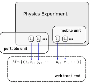
Figure 1. Conceptual diagram depicting main components of the setting. Each sensor (sx) gives a
measurement (xi) at a certain time (ti). Measurements are collected and rendered as series of vectors
3
OPEN SOURCE HARDWARE AND SOFTWARE PLATFORM FOR PHYSICS
LABORATORY
Most physics demonstrations on kinematics involve one or several mobile elements whose motion is analyzed and the goal of the experimenter is to be able to measure one or more magnitudes relevant for the experiment as position, angle, time, speed or acceleration. Then the system designed for such experiments should include some sensors as accelerometer, gyroscope, distance sensor or light gate sensors, but could also include others as GPS or even magnetometer to allow for different experimental configurations.
Figure 1 presents a simple design that accounts for the initial setting in a way that including a mobile unit with sensors attached to the mobile object whenever it is possible. In some cases, as for example when the masses or the shape and size of the mobile objects are very specific, to include this mobile unit could not be possible. However, in other experiments, if, for example, the measured parameters are external to the moving object we should also consider acquiring data using an external portable unit complying with the reusability requirement (iii). The front end system must render a table comprising the time tagged observations vectors
M
(see Figure 1) acquired through the sensors of our system. In order to match some of the general requirements previously stated, as well as to ease the necessary displacements or movements in the experiment, wireless communications whenever practical, like Bluetooth and WiFi are preferred, to link the mobile unit and the portable unit and also the access to the web front-end. In this way the experiment can be performed without wires constraining the movements or altering the body movement.Our previous experience in this kind of embedded systems has guided us in the adoption of closely resembling systems and technologies [12] so that our design comprises the following elements:
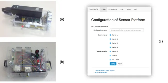
Mobile unit – At its core it has an Arduino Nano v3 board connected to a sort of sensors and a serial
connection device. The present configuration (see Figure 2.a) includes the following sensors: Infra-red line tracker, 6DOF MPU6500 (motion processing unit) from Invensense Inc. consisting of 3-axis accelerometers and gyroscopes, and HC-SR04 ultrasound distance sensor. The ATMEL serial interface of the microcontroller is connected to a HC-06 Bluetooth device. Some other complimentary components are a battery based power supply, pushbuttons and informative LEDs. The actual design built also permits to include a MPU 9250 with 3-axis magnetometer giving an inertial measurement unit of 9DOF instead of the MPU6500.
This subsystem is programmed in Arduino 1.6 and implements a simple protocol through a serial wireless connection established using Bluetooth connectivity. The protocol permits to initialize the microcontroller as well as start and stop the data acquisition. This sampling proceeds at the maximum speed attainable by the system given that the limiting factor here is the speed of the Bluetooth connection.
Portable unit – Consists of a Raspberry Pi2 unit with Raspbian Jessie as operating system (see Figure
2.b). The core process of the unit is a user level process programmed in Go that governs the overall system and offers a web front-end and a Rest API suitable to be used by other client side processes. The unit supports the WiFi connection through a USB dongle, while another USB device provides the Bluetooth connectivity with the mobile unit. Therefore, this portable unit stores in its local persistent storage (SD card) the measurements released by the mobile unit and permits its retrieval by any kind of device like a laptop or a tablet by the experimenter through the Rest API.
Additionally, this portable unit can be used to allocate any other wired connected sensor, using the GPIO of the Raspberry Pi. In our case we have added four infra-red emitter-receivers suitable to be used to detect a mobile object. This can be used, for example, to measure instant speeds of carts with small cardboard cards attached to them that pass in front of the infra-red detectors. The unit can also be powered using a micro USB connector, making it suitable to outdoors physics experiments while connected to an ordinary USB battery.
A complete description of our system can be found at our git repository [11], where the following documents and programs can be found:
CAD files in FreeCAD format for hold the IR beacons and platforms to place them at the side of an air track.
Go language code of the Raspberry Pi unit that controls the main loop of the web front-end, interfaces with the mobile unit, and acquires data from the IR beacons.
Arduino code for governing the mobile unit.
The git repository is licensed with an open source license and we offer it to the academic community for collaborations in order to extend and maintain the code and plot diagrams.
3.1 Methodological Usage of the Platform on Laboratory Practice
The platform described here can be used in different ways depending on the student skills and on their physics knowledge. For the less skilled students a more detailed guide of the experiment is mandatory with step by step descriptions for the usage of the platform and the actual practice. However our aim is to give the students less detailed descriptions of the experiment (arrangement and procedure) as their experimental skills and knowledge increase. For more skilled students we would give them in advance to their work in the laboratory only a brief description of the sensors included in the platform as well as the final aims of the experiment. In this way they could have some days to figure out how to do the needed measurements from the available sensors, how to analyze their measurements or how contrast their experimental results with the theory they know. In this way, we want to improve their laboratory skills and physics learning but also to promote their self-reliance.
4
APPLICATION TO A MOVING OBJECT ON AN AIR TRACK.
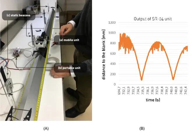
Our very first prototype of the system was built with a sort of sensors usable to be embedded in an air track kinematics experiment. In order to the cart to move easily without friction to the air track, and taking into account the power of the air pump used in our setting, the mobile unit, that must be attached on the moving cart, must be light enough. Without the power-bank, the weight of the used unit is 110 g, mainly due to the polycarbonate box encasing the electronics. Figure 3.A shows a snapshot of an actual experimental setup where the two main units and a disposition of IR detectors next to the air track can be seen.
This configuration permits different experimental measurement settings depending on the included sensors that can be used. So, every instructor can decide which of them use in the experiment as well
(a)
(c)
(b)
as the aim of the measurement proposed to the students. Also, the students can design their own project in an easy way, simply selecting at the web front-end which sensors are going to be used and, then applying accordingly the adequate kinetic equations to interpret the results.
In a similar way, the student could take the initiative in designing a particular measurement setting combining the outcomes resulting from different sensors. For example, using the IR line tracker of the mobile unit, the student could measure instant speed at different positions or times. Further physical analysis could also be done, for example, by combining those data with the acceleration measured by the accelerometer.
The acquired data is stored in the SD card of the portable unit under the form of a plain CSV file with lines tagged with the acquisition time, so they are suitable to be loaded in any practical data analysis software. Figure 3.B shows actual data provided by the system for the ultrasonic distance measure sensor (HC-SR04). In this very case, also the portable unit is configured as an Ethernet WiFi access point so the computing device used by the student to access the web front-end needs no kind of internet access. In case there is an infrastructure WiFi support or cable access, the Raspberry Pi can provide the same service through internet.
In this laboratory work with the air track the students can analyze different linear movements. For example, by setting the air track horizontally the students can inquire into the linear movement at constant speed or collisions between two carts. For the first case it would be enough to have a one moving cart and simply push it to start its movement. Then the students can measure its instant velocity at different positions as it advances along the air track. For the second case the students must have two carts with equal or different masses and study their velocities before and after the collision depending on their masses and on their initial kinetic. If the students set the air track forming a small angle with the horizontal and then release the cart, so that it starts an accelerated movement due to the track inclination, then the measurement of times, instant speeds or traveled distances can be used to obtain the movement acceleration. Later, they can compare the data coming from some sensors with
(A) (B)
the expected values computed from the model. From it and the angle between the track and the horizontal the students can also calculate the value of the gravity acceleration.
Practical sessions in the laboratory usually develop according to a guide prepared by the instructor and supplied to the students in advance. This document includes explanations on the theoretical background of the experiment and details the disposition of the equipment so that the students could follow precisely the given indications to collect sets of measurements, in a similar fashion as a cooking recipe does. With the arrangement proposed here a more open experiment can be done depending on the students’ skills and knowledge. For example simple explanations on the different sensors included in the platform can be given and after stating the experiment aims the students could decide which sensors they prefer to use or how to combine measurements from different sensors to obtain the needed physical data.
As expected, the precision of the measured samples obtained with the ultrasonic distance sensor (HC--SR04) worsens at a certain distance depending on the technology and quality of the sensor, as can be seen in the plot of the Figure 3.B. Also we can see that the area and material forming the target the ultrasound waves are aimed to affect strongly the accuracy of the outcomes. This, far from being a hindrance to design a proper physics experiment is an opportunity for the instructor to include several challenges to the student that has to grasp the main concepts that models the task and also be able to compute and extract conclusions from the experimental data.
5
CONCLUSIONS
This paper describes an actual system suitable enough to be used in an academic environment as a tool to ease doing kinematics demonstrations and experiments. The system presented is open source, and is intended to be stable and robust; its configuration is quite simple through a web interface accessible with any web based computing device. The system has as few cables as possible and can rely only on batteries without network infrastructure support which allow us to use it even in outdoors experiments. The cost of the overall system here described without accounting working hours is in the order of no more than 200 €.
The system is in fact an extensible platform that could be modified to add real time graphics and smart support to its operation and to include additional sensors. We are willing to see extensions to it even new open source hardware and software initiatives aimed to provide affordable physics experiments to undergraduate and school students. Along this coming course a research with a significant number of students will be made, so we expect that some interesting conclusions on their learning and engagement improvements will be drawn.
ACKNOWLEDGEMENTS
We want to give our thanks to the Vicerrectorado de Innovación Docente that founded the Programa de Innovación Docente 2015-16, and our project “Sensorización de Prácticas Docentes de Laboratorios de Física con Hardware Open Source” (PID1516-161). Also we want to thanks the Department of Physics of Condensed Matter (University of Valladolid) that granted materials and the use of the laboratory at the Engineering School of Valladolid (Spain).
REFERENCES
[1] S. Tormaken, D. R. Simons, R. W. Helms, W. E. Johns, K. E. Schriver y M. S. Webster, «Motion tracking in undergraduate physics laboratories with the Wii remote,» American Journal of Physics,
vol. 80, nº 4, pp. 351-354, 2012. doi:http://dx.doi.org/10.1110/1.3681904
[2] K. Hochberg, J. Kuhn y A. Müller, «Science Education with handheld devices: A Comparison of Nintendo WiiMote and iPod touch for kinematics learning,» Perspectives in Science, p. in press, 2016. doi:http://dx.doi.org/10.1016/j.pisc.2016.01.008
Information Technology, vol. 17, nº 1, pp. 31-50, 2015. doi:http://dx.doi.org/10.4018/JCIT.2015010103
[4] M. A. González, J. B. da Silva, J. C. Cañedo, F. Huete, O. Martínez, D. Esteban y M. A. González, «Doing physics experiments and learning with smartphones,» de Proceedings of the 3rd International Conference on Technological Ecosystems for Enhancing Multiculturality, Porto, Portugal, 2015. doi:http://doi.acm.org/10.1145/2808580.2808626
[5] K. M. Thomas, B. W. O'Bannon y N. Bolton, «Cell phones in the classroom: Teachers' perspectives of inclusion, benefits and barriers,» Computers in the Schools, vol. 30, nº 4, pp. 295-308, 2013. doi:http://dx.doi.org/10.1080/07380569.2013.844637
[6] B. W. O'Bannon y K. Thomas, «Teachers perceptions of using mobile phones in the classroom: Age matters!,» Computers & Education, vol. 74, pp. 15-25, 2014.
doi:http://dx.doi.org/10.1016/j.compedu.2014.01.006
[7] J. M. Pearce, «Building research equipment with free, open-source hardware,» Science, vol. 337, nº 6100, pp. 1303-1304, 2012. doi:http://dx.doi.org/10.1126/science.1228183
[8] R. Sallier, R. Mißler y A. & Schütze, «VenDASys—A versatile experimentation platform for educational purposes,» de IEEE EDUCON 2010, Madrid, Spain, 2010, April.
doi:http://dx.doi.org/10.1109/EDUCON.2010.5492576
[9] B. Huang, «Open-source Hardware – Microcontrollers and Physics Education – Integrating DIY Sensors and Data Acquisition with Arduino,» de 2015 ASEE Annual Conference and Exposition, Seattle, Washington, 2015. doi:http://dx.doi.org/10.18260/p.24542
[10] D. E. Bolanakis, K. T. Kotsis y T. Laopoulos, «Ethernet and PC‐based experiments on barometric altimetry using MEMS in a wireless sensor network,» Computer Applications in Engineering Education, vol. 24, nº 3, pp. 443-455, 2016. doi:http://dx.doi.org/doi:10.1002/cae.21722
[11] Grupo TIA, "Repository: Open Source Sensor Platform for Physics Laboratory," 25 September 2016. [Online]. Available: https://github.com/percomp/OSHIWASP.