Preprint of the paper
"A BEM Approach for Grounding Grid Computation"
I. Colominas, F. Navarrina, M. Casteleiro (1994)
En "Boundary Element Method XVI", Sección 4: "Electromagnetics", pp. 117--124; C.A.
Brebbia (Editor);
Computational Mechanics Publications, Southampton, UK (ISBN: 1-85312-283-1)
I. Colominas, F. Navarrina and M. Casteleiro
Depto. de Metodos Matematicos y de Representacion
E.T.S. de Ingenieros de Caminos,Canales y Puertos
Universi dad de La Coru~na
Campus de Elvi~na, 15192 La Coru~na, SPAIN
SUMMARY
Groundingsystemsare designed to preserve human safety and grant
theintegrity ofequipmentsunderfaultconditions. Toachievethesegoals,
the equivalent electrical resistance of the system must b e low enough to
ensure that fault currents dissipate (mainly) through the grounding
elec-tro de into the earth, while maximum p otential gradients b etween close
p oints on the earth surface must b e kept under certain tolerances (step
and touch voltages) [1,2].
In this pap er, we present a Boundary Element approach for the
nu-merical computation of grounding systems. In this general framework,
former intuitive widespread techniques (such as the Average Potential
Metho d) are identied as the result of sp ecic choices for the test and
trial functions,while the unexp ected anomalousasymptotic b ehaviourof
these kind of metho ds [3] is mathematically explained as the result of
suitable assumptionsintro duced in the BEM formulation to reduce
com-putationalcost. Ontheotherhand,theuseofhighorderelementsallowto
increase accuracy, while computing time is drastically reduced by means
of new analytical integration techniques. Finally, an application example
to a real problem is presented.
INTRODUCTION
Faultcurrentsdissipationintotheearthcan b emo delledby meansof
Maxwell'sElectromagneticTheory[4]. Onaregularbasis,theanalysiscan
b econstrainedtotheobtentionoftheelectrokineticsteady-stateresp onse,
and the inner resistivity of the earthing electro de can b e neglected. In
these terms, the 3D p otentialproblem can b e written as
=0
e
gradV; div() =0 in E;
t
nnnnnnnnnnnnnn E
e
E
n n n E
its normalexteriorunit eldand0the earthingelectro desurface[5]. The
solutiontothisproblemgivesthep otentialV andthecurrentdensity
at
an arbitraryp ointxxxxxxxxxx x x x x
when theearthing electro de is energizedto p otential
V 0
(GroundPotentialRiseorGPR) withresp ect toremoteearth. Onthe
otherhand,b eingnnnnnnnnnn n n n n
thenormalexterioruniteldto0,theleakagecurrent
density atanarbitraryp ointontheearthingelectro desurface,thetotal
surge current I
0
leaked into the earth and the equivalent resistance R
eq
of the earthingsystem can b e written as
= t
n nnnnnn
nnnnnnn; I 0
=
Z Z
0
d0; R
eq =
V 0
I 0
: (2)
For most practical purp oses [3], the soil conductivity tensor
e can
b e replaced bya meassuredapparentscalarconductivity (hyp othesisof
homogeneus and isotropic soil). Since V and
are prop ortional to the
GPR value, the normalized b oundary condition V
0
= 1 is not restrictive
atall. Furtherpracticalsimplications(atearthsurface)allowtorewrite
problem (1) as a DirichletExterior Problem[4,5].
In most of cases, the earthing electro de consist of a numb er of
in-terconnected bare cylindricalconductors, horizontally buried and
supple-mentedby a numb erof verticalro ds, whichlenght/diameterratio usesto
b e relatively high ( 10
3
). Because of this kind of geometries,
analyti-cal solutions to problem (1) can not b e derived for practical cases. On
the otherhand,standardnumericaltechniques(suchasFiniteDierences
or Finite Elements) require discretization of domain E, which leads to
unacceptable memorystorage and computing time.
Since computation of p otential is only required on the earth surface
andtheequivalentresistancecanb eeasilyobtainedintermsoftheleakage
current(2),weturnourattentiontoaBoundaryElementapproach,which
would only require discretizationof the earthinggrid surface 0.
VARIATIONAL STATEMENT OFTHE PROBLEM
Further analytical work [5,6,7] on problem statement (1) allow to
express the p otential V at an arbitrary p oint xxxxxxxxxx x x x x
on the earth E in terms
of the leakage currentdensity , in the integral form
V(xxxxxxxxxx xx x
x)=
1
4
Z Z
20
k(xxxxxxxxxx x x x x;
)(
) d0; (3)
k(xxxxxxxxxx xx x x;
)=
1
r (xxxxxxx xxx x x x x;
)
+ 1
r (xxxxxxxxxx x x x x;
0
)
; r (xxxxxxxxxx xx x x;
)=jxxxxxxxxxx
x x x x
0
j; (4)
where 0
is the symmetricof
with resp ect to the earth surface.
Sincethisexpressionholdson0,theb oundaryconditionV
0
Moreover,this problem can b e written in the weaker variational form:
Z Z
20
w (
) (V(
)01) d0 = 0 (5)
for all memb ersw () of asuitable class of test functionson 0.
BOUNDARY ELEMENTAPPROACH
For given sets of 2D b oundary elements f0
; = 1;:::;Mg, and
trial functions fN
i (
);i =1;:::;Ng dened on 0, the earthing electro de
surface 0 and the leakage current density can b e discretized as
0=
M [
=1 0
; ()= N X
i=1
i N
i
(); 20; (6)
which leads tothe following discretized formof (3):
V(xxxxxxxxxx x x x
x)=
N X
i=1 M X
=1
i V
i
(xxxxxxxxxx x x x
x); V
i
(xxxxxxxxxx x x x
x)=
1
4
Z Z
20
k(xxxxxxxxxx
x x x x;
)N
i (
) d0:
(7)
Finally,foragivenset fw j
(
);j =1;:::;Ngof testfunctionsdened
on 0, variational statement (5) is reduced to the linearequations system
N X
i=1 R
ji
i
=
j
; j=1;:::;N; (8)
R ji
= M X
=1 M X
=1
Z Z
20
w
j ()V
i
()d0; j
= M X
=1
Z Z
20
w
j
()d0:
(9)
Itcanb eeasilyveriedthattheN2N matrixin (8)is notsparse. In
addition,computationofco ecientsR
ji
in(9)requiresintegrationona4D
domain, since 2D integrationmust b e p erformed twiceover the electro de
surface [8]. Again we must intro duce some additional simplications in
order to reduce computational costunder acceptablelevels.
APPROXIMATED 1DVARIATIONAL STATEMENT
Withthisscop e,it seemsreasonable toconsiderthatthe leakage
cur-rent density is constant around the cross section of the cylindrical
elec-tro de[8,9]. Thishyp othesisiswidelyusedinmostofthepracticalmetho ds
b
2L b e the orthogonal projection of a generic p oint
2 0. Let (
b
) b e
the conductordiameter, andlet b(
b
)b e theapproximatedleakagecurrent
density at this p oint(assumed uniform around the crosssection). Inthis
terms we can writeexpression (3) in the form
b V(xxxxxxx
xxx x x x x)= 1 4 Z b 2L ( b ) k(xxxxxxx
x x x xx x x; b ) b(
b
)dL; (10)
b eing k(xxxxxxx
x x x xx x x; b
) the averageof kernel (4) around crosssection at
b [8,9].
Because the leakage current is not really uniform around the cross
section,variationalequality(5)do esnotholdanymoreifweuseexpression
(10) insteadof (3). Therefore,we mustrestrict theclass of trialfunctions
to those with circumferentialuniformity,obtaining
1 4 Z b 2L (b )w(bb
) " Z b 2L ( b ) k(b ; b )(b
b )dL # dL= Z b 2L (b )w(bb
)dL;
(11)
for all memb ers b
w (b
) of a suitable class of test functions on L, b eing
k(b ; b
) the averageof kernel(4) aroundcrosssections at
b and b [8,9].
APPROXIMATED 1DBOUNDARY ELEMENTAPPROACH
Forgivensets of 1Db oundaryelementsfL
;=1;:::;mg,andtrial
functionsf b N i ( b
);i=1;:::;ngdenedonL, thewhole setof axiallines of
the buried conductors L and the unknown leakage current density b can
b e discretized as
L= m [ =1 L
; b(
b )= n X i=1 b i b N i ( b ); (12)
which leads tothe following discretized formof (10)
b V(xxxxxxx
x x x xx x x)= n X i=1 m X =1 b i b V i
(xxxxxxx x x x x x x x); b V i
(xxxxxxx x x x x x x x)= 1 4 Z b 2L ( b ) k(xxxxxxx
x x x xx x x; b ) b N i ( b ) dL: (13)
Finally,fora given set fwb j
(b); j=1;:::;ng of test functions dened
on L,variationalstatement(11)is reducedtothe linearequationssystem
n X i=1 b R ji b i
=b j
; j=1;:::;n; b
j = m X =1 Z b 2L
(b)wb j
(b) dL; (14)
b R ji = 1 4 m X =1 m X =1 Z b 2L (b )wb
Extensive computingisstill requiredto evaluatethe averaged kernels
k(xxxxxxx
x x x xx x x; b ) and k (b ; b
) by means of circumferential integration around cross
sections atp oints b
andb
. Thecircumferentialintegrationcanb eavoided
by means of thefollowing approximations [8,9]:
k(xxxxxxx
xxx x x x x; b ) 1 b r(xxxxxxx
xxx x x x x; b ) + 1 b r(xxxxxxx
xxx x x x x; b 0 ) ! ; k(b ; b ) 1 b b r(b;
b ) + 1 b b r(b ; b 0 ) ! ; (16) b r(xxxxxxx
x x x xx x x; b )= s
jxxxxxxx xxx x x x x0 b j 2 + 2 ( b ) 4 ; b b r(b ; b )= s jb 0 b j 2 + 2 ( b )+ 2 (b ) 4 :
Now, forsp ecicchoicesof the trialandtest functionsweobtain dierent
formulations. Thesimplest ofthesecanb e identiedwithwidespread
pre-viousmetho dsbased on intuitiveideas, suchas sup erp osition of punctual
current sources and error averaging [1,2,3]. Thus, for constant leakage
currentelements,aGalerkintyp e choiceforthetrialfunctionsleadto the
Average PotentialMetho d [1,2,3].
The unrealistic results [3] obtained with this kind of metho ds when
segmentationofconductorsis increasedcanb e mathematicallyexplained,
since approximations (16) lo ose accuracy when the size of the elements
is in the order of magnitude of the diameter of the bars, and linear
sys-tem (14) b ecomes ill-conditioned. However, results obtained for low and
medium levels of discretization have b een proved to b e suciently
accu-rateforpracticalpurp oses[8,9]. Ontheotherhand,ends andjunctionsof
conductors are not taken intoaccount in this formulation. Thus, slightly
anomalous lo cal eects are exp ected at these p oints, but global results
should not b e noticeably aected.
Computation of remaining integrals in (13) and (15) is not obvious.
The cost of numerical integration is out of range, due to the undesirable
b ehaviour of the integrands. For this reason, it has b een necessary to
derivesp ecic analytical integrationtechniques [11].
For Galerkin typ e formulations the matrix of co ecients in (14) is
symmetric and p ositive denite [10]. Because of this fact, a conjugate
gradient metho d can b e used, and the non-sparsity of the matrix can b e
partiallyovercome. Atthesametime,linearandparab olicleakagecurrent
elementsallowtoincreaseaccuracy,andlargeproblemscanb esolvedwith
acceptable computing requirements [8,9,11].
CONCLUSIONS
A Boundary Element approach for the analysis of substation
earth-ing systems has b een presented. Some reasonable assumptions allow to
practi-ments. This formulation has b een implemented in a Computer Aided
Design Systemdevelop ed during the last few years.
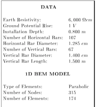
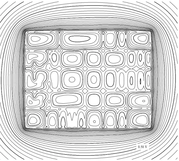
This approach has b een applied to a real case: the E. Balaidos II
substation grounding (close to the city of Vigo, Spain). The plan and
characteristics are presented in Figure 1. Results are given in Figure 2.
Each barwasdiscretizedin onesingle parab olicelement. The mo del(174
elementsand315degreesoffreedom)requiredonly 94secondsof cputime
on a Vax-4300 computer. At the scale of the whole grid, results are not
noticeably improvedby increasing discretization.
ACKNOWLEDGEMENTS
Thisworkhasb eenpartiallysupp ortedbytheSubdireccionGeneralde
Produccion Hidra ulica , Transporte y Transformaci on de \Union Fenosa",
and by a research fellowshipof the Universidad de La Coru ~na.
REFERENCES
1. SverakJ.G. etal{\Safe SubstationsGrounding.PartI",IEEE Tran.
on Power App. and Systems, 100 (9), 4281{90, (1981).
2. SverakJ.G.etal{\SafeSubstationsGrounding.PartI I",IEEETran.
on Power App. and Systems, 101 (10), 4006{23, (1982).
3. GarretD.L.and Pruitt J.G. {{\ProblemsEncounteredwith the
Av-eragePotentialMetho dofAnalyzingSubstationGroundingSystems",
IEEETrans. on Power App. and Systems, 104(12),3586{96,(1985).
4. DurandE. {
Electrostatique, Masson,Paris, (1966).
5. Navarrina F., Moreno L., Bendito E., Encinas A., Ledesma A. and
Casteleiro M. { \Computer Aided Design of Grounding Grids: A
Boundary Element Approach", Mathematics in Industry, 307-314,
KluwerAcademic Pub.,Dordrecht,(The Netherlands),(1991).
6. StakgoldI.{BoundaryValueProblems ofMathematicalPhysics,
Mac-Millan,London, (1970).
7. Dautray R. and Lions J.L. {Analyse Mathematique et Calcul Num
e-riquepour lesSciencesetlesTechniques,Vol.6,Masson,Paris,(1988).
8. Navarrina F., Colominas I. and Casteleiro M. { \Analytical
Inte-gration Techniques for Earthing Grid Computation by BEM", Int.
Congress Num. Meth. Engrg. App. Sci., Concep cion, (Chile),(1992).
9. Navarrina F., Colominas I. and Casteleiro M. { \Una Formulacion
Aproximada mediante el Meto do de Elementos de Contorno para
la solucion de Problemas en Teora del Potencial", II Congreso de
Metodos Numericos en Ingeniera, LaCoru ~na,(1993).
10. JohnsonC. {Numerical Solution of Partial Dierential Equations by
the Finite Element Method, CambridgeUn. Pr.,New York,(1987).
11. ColominasI.,NavarrinaF.andCasteleiro M.{ \FormulasAnalticas
EarthResistivity: 6;000cm
GroundPotential Rise: 1V
Installation Depth: 0:800m
Numb er of Horizontal Bars: 107
Horizontal BarDiameter: 1:285cm
Numb er of Vertical Bars: 67
Vertical BarDiameter: 1:400cm
Vertical BarLength: 1:500m
1D BEM MODEL
Typ e of Elements: Parab olic
Numb er of No des: 315
Numb er of Elements: 174
Vertical barsmarked withblack p oints
Figure 1.|E. Balaidos I I Grid: Plan (Scale=1:1000), Problem Characteristics
Fault Current: 2:46462A
Equivalent Resistance: 0:40574
CPU Time: 94sec
Computer: VAX{4300
Surface p otential contours plotted every
0:02V. Thick contoursevery 0:10V.
0.50 V
Figure 2.|E.Balaidos I IGrid: ResultsobtainedbyBEM(1parab olicelement