UNIVERSIDAD DE VALLADOLID
ESCUELA DE INGENIERIAS INDUSTRIALES
Grado en Ingeniería Mecánica
Effects of Processing Parameters on the
Sur-face Quality of Web Based Thermoplastic
Composites Manufactured in an Automated
Process
Autor:
Barbero García, Elías
María Isabel Sánchez Bascones
Universität Augsburg
TFG REALIZADO EN PROGRAMA DE INTERCAMBIO
TÍTULO:
Effects of Processing Parameters on the Surface Quality of Web
Based Thermoplastic Composites Manufactured in an Automated
Process.
ALUMNO:
Elías Barbero García
FECHA:
15/09/2017
CENTRO:
Universität Augsburg
RESUMEN
:Este TFG se centra en la mejora de la calidad superficial de las piezas producidas a partir de web composites mediante un proceso automatizado. Para lograr esto, se llevó a cabo un estudio
pormenorizado de los factores de influencia. Diversas pruebas junto a un diseño experimental
fueron realizadas buscando conocer cuánto influye cada factor en la calidad superficial. Finalmente, a partir de los resultados derivados de esta experimentación, distintas pruebas
fueron ejecutadas con el objetivo de obtener piezas con una calidad superficial mejorada.
CINCO PALABRAS CLAVE
:The work was submitted to the
Institut für Textiltechnik Augsburg gGmbH
Univ.-Prof. Dr.-Ing. Stefan Schlichter
Effects of Processing Parameters on the Surface Quality of Web Based
Thermoplastic Composites Manufactured in an Automated Process
Presented as:
Bachelor Thesis
by:
Elias Barbero
Matr.-No.
1528523
1
stexaminer: Univ.-Prof. Dr.-Ing. Stefan Schlichter
2
ndexaminer: Prof. Dr. Siegfried R. Horn
Supervisor:
Dr.-Ing. Philipp Abel
2017
Bachelor Thesis
Effects of Processing Parameters on the
Surface Quality of Web Based
Thermo-plastic Composites Manufactured in an
Automated Process
Elias Barbero
•Cutting the non-woven material •Manual
heating press •Cooling under
pressure
Preparation of the webs
•Places the web in the oven •Takes the web
from the oven •Takes the web
to the mould Robot
•Compress the web giving it the desired shape
Abstract
This thesis focuses on the improvement of the surface quality of the parts produced from web-based thermoplastic composites by an automatic process. For bringing to
successful conclusion this assignment a detailed study of the factors influencing this
aspect was completed. Later, early trials together with an experimental design were carried out in order to see how each factor influences the quality of the surface. Finally,
from the results derived by the previous experimentation, several tests were executed
with the aim of getting final parts with an improved surface quality.
Index
1 Introduction and Objectives ... 13
2 State of the art ... 15
2.1 Introduction to composite materials ... 15
2.2 Carbon fibres ... 16
2.2.1 Introduction to carbon fibres ... 16
2.2.2 Manufacturing process of carbon fibre ... 16
2.2.3 Properties of carbon fibres ... 17
2.2.4 Types of carbon fibres ... 18
2.3 Recycling of composites ... 18
2.3.1 The need of recycling ... 18
2.3.2 Legislation ... 19
2.3.3 Thermoplastics and thermosetting plastics ... 20
2.3.4 Recycling processes ... 21
2.3.5 Critical length of fibre ... 23
2.4 Matrix ... 24
2.4.1 Polyamid ... 24
2.5 Nonwoven ... 25
2.5.1 Concept of nonwoven ... 25
2.5.2 Dry-Laid... 26
2.5.3 Dilo compact system ... 28
2.6 Component production of carbon fibre ... 29
2.6.1 Thermoforming of organic sheets ... 29
2.6.2 Resin transfer moulding ... 29
2.6.3 Thermoforming and injection moulding ... 30
3 Production process ... 31
3.1 Infrared oven ... 32
3.2 Handling system ... 32
3.3 Pressing unit ... 34
3.4 Induction unit ... 35
4 Preparation of the experiments ... 37
4.1 Objectives ... 37
4.2 Preparation of the preforms ... 37
4.3 First trials ... 38
4.3.1 Parameters of the first experiments ... 39
4.3.2 Conclusions and images of the first experiments ... 40
4.3.3 Images of the first experiments ... 40
4.4 Experimental design ... 43
4.5.1 Temperature ... 46
4.5.2 Pressure ... 46
4.5.3 Time ... 46
4.5.4 Press parameters ... 47
4.5.5 Induction unit ... 48
5 Evaluation and statistical study ... 49
6 Final experiments ... 52
6.1 Reduction of the level of penetration of the needles ... 52
6.2 Reduction of the cycle times ... 53
6.3 Thermal impact reduction ... 53
6.4 Application of a layer of polyamide ... 55
6.5 Results and images ... 56
7 Summary, conclusions and outlook ... 63
7.1 Summary ... 63
7.2 Conclusions ... 63
7.3 Outlook ... 65
8 Bibliography ... 66
9 Attachments ... 69
List of Figures
Fig. 2.1: Stress vs strain for fibre and matrix separated (a) and altogether (b).
[CR14] ... 15
Fig. 2.2: Simplified representation of manufacturing process of carbon fibres from PAN precursors. [PH10] ... 17
Fig. 2.3: Global demand for Carbon fibre in 1,000 tonnes 2010 to 2022 (*Estimation). ... 19
Fig. 2.4: Pyramid in regard to waste management. [SGG16] ... 20
Fig. 2.5: Energy demand in composite recycling methods. [SGG16] ... 22
Fig. 2.6: Energy contrast between production and recycling carbon fibre processes... 22
Fig. 2.7: Stress-position depending on the length of the fibre. [CR14] ... 23
Fig. 2.8: Possible layups and applications examples of organic sheets. [SGL17] .... 26
Fig. 2.9: Diagram of the carding process. [ED17] ... 27
Fig. 2.10: Diagram of the airlaid process. [ED17] ... 27
Fig. 2.11: Diagram of Dilo system for nonwoven production. [Mar17] ... 28
Fig. 2.12: Key stages in the thermoforming process for reinforced thermoplastic composites. [RAR12] ... 29
Fig. 2.13: Step process of thermoforming combined with injection moulding. [Kra17] ... 30
Fig. 3.1: Top view of the manufacturing process. [Ege17] ... 31
Fig. 3.2: Infrared oven and its components. [EnM16] ... 32
Fig. 3.3: Stäubli robot and its rotation axes. [EnM16] ... 33
Fig. 3.4: Image of the needle group in detail (extended position). ... 33
Fig. 3.5: Image of the second holding system with vacuum circuit. ... 34
Fig. 3.6: Pressing unit opened with the pressing and injection moulds. ... 35
Fig. 3.7: Plant vision of the induction plates. ... 36
Fig. 4.1: Flowchart of the web preparation process. ... 38
Fig. 4.3: Tª of 250 ºC without polyamide with critic movements at 100% speed. ... 41
Fig. 4.4: Tª of 300 ºC without polyamide with soft movements at 10% speed. ... 42
Fig. 4.5: Tª of 275 ºC with polyamide with critic movements at 50% speed. ... 42
Fig. 4.6: Tª of 225 ºC with polyamide with critic movements at 100% speed. ... 43
Fig. 4.7: Tª of 275 ºC with polyamide with critic movements at 100% speed. ... 43
Fig. 4.8: Flowchart of the polyester webs preparation process. ... 45
Fig. 4.9: Flowchart of the automated process cycle done by the robot. ... 47
Fig. 4.10: Representation of speed (mm/s) and force (kN) versus distance (mm). .... 47
Fig. 6.1: Two needle grippers holding a composite web. [Die17] ... 52
Fig. 6.2: Distribution of temperatures in a composite web before being compressed. Source: ITA. ... 54
Fig. 6.3: Explanatory flowchart of the process cycle done by the robot. ... 55
Fig. 6.4: Final piece corresponding to web number 1. ... 57
Fig. 6.5: Final piece corresponding to web number 2. ... 57
Fig. 6.6: Final piece corresponding to web number 4. ... 58
Fig. 6.8: Final piece corresponding to web number 6. ... 59
Fig. 6.9: Final piece corresponding to web number 9. ... 59
Fig. 6.10: Final piece corresponding to web number 10. ... 60
Fig. 6.11: Final piece corresponding to web number 11. ... 60
Fig. 6.12: Comparison between webs 1 and 4 needle marks. ... 61
Fig. 6.13: Comparison between webs 5 and 6 needle marks. ... 61
List of Tables
Tab. 2.1: Carbon fibre supply and demand. [A16] ... 19
Tab. 2.2: Properties of polyamide and polyester. [RLL11] ... 24
Tab. 2.3: Influence of water content on polyamide. [RLL11] ... 25
Tab. 4.1: Parameters values of the figures attached. ... 41
Tab. 4.2: Dependent variable combinations in the experiment. ... 44
Tab. 5.1: Roughness average values from different zones of the tested webs. ... 49
Tab. 5.2: ANOVA table for variable Roughness, type III Sums of Squares. ... 50
Tab. 6.1: General characteristics of the needle group. [Die17] ... 52
Tab. 6.2: Specifications of the last experiments made. ... 56
Tab. 6.3: Main features of web number 1. ... 57
Tab. 6.4: Main features of web number 2. ... 57
Tab. 6.5: Main features of web number 4. ... 58
Tab. 6.6: Main features of web number 5. ... 58
Tab. 6.7: Main features of web number 6. ... 59
Tab. 6.8: Main features of web number 9. ... 59
Tab. 6.9: Main features of web number 10. ... 60
Tab. 6.10: Main features of web number 11. ... 60
Abreviations
CF Carbon Fibre
TFP Tailored Fibre Placement
CFRC Carbon Fibre Reinforced Composites
CFRP Carbon Fibre Reinforced Plastics
RTM Resin Transfer Moulding
ITA Institute of Textile Technology Augsburg
PAN Polyacrylonitrile
PE Polyester fibre
PA Polyamide
Dilo Dilo KO1.34290.16 ITA compact system
1
Introduction and Objectives
Actually, composite recycling is still in development. It is necessary to mention that the
majority of products that contain composite components have a long service life and will not be available for recycling in some years by which the growth of the recycling
industry does not resemble to the one of manufacturers.
Apart from the previously mentioned, there is another challenge that must be over-come. Not all the companies can work with recycled fibres (is necessary to align the
recovery fibres), which is more complicated than working with virgin fibres.
Further-more, if we wish similar composites to those obtained with virgin fibres we need an almost perfect alignment, which is a difficult task to accomplish.
Despite these disadvantages, the high value of carbon fibre makes new companies
arise all over the world. This is the case of the Institute of Textile Technology Augsburg (ITA) that employs recycled carbon fibres in combination with various thermoplastic
matrix producing different types of non-woven.
The ITA has also implemented a production process of web based carbon fibre rein-forced composites in its headquarters in Augsburg. It is a process that combines the
thermoforming and subsequent compression with plastic injection. This process results
in the production of final parts with mechanical characteristics comparable to those of metals.
This thesis that is presently exposed would have no meaning if it is not for two other
thesis which have been carried out by my colleagues in parallel. Each segment of the process has been approached particularly by every author.
Miguel has focused on the preparation of preforms and his subsequent reduction of
times, Gonzalo in the optimization of the robots cycle and Elias in the surface quality of the parts resulting from the process. Miguel and Gonzalo thesis are detailed in
Bibliog-raphy with the references [Gar17] and [Die17] respectively.
But before focusing on each part it is necessary to have an idea of the general process. This process is encompassed in another larger process in which the treatment of
recy-cled carbon fibre is present and also is its subsequent conversion into rolls of
non-woven textile. This large process includes every practice from the recycling of carbon fibres to the production of final parts with a defined functionality.
In the image below a schematic representation of the distributions commented
previ-ously can be appreciated. On the left, a flowchart of the different segments treated by each author is displayed and on the right, a sector diagram of the whole process from
Fig. 1.1: Descriptive flowchart and sector diagram of the process.
The objective of this thesis is the improvement of the surface quality of the pieces
pro-duced in this automated process. For this purpose, a thorough study of the factors of the process influencing the surface quality of the piece was completed.
Since there were a large number of factors, several first trials were carried out on a
segment of the process to determine the type of influence of certain parameters.
Later, with the results and conclusions derived from the previous trials, an experimental
design applied to the entire automated process was performed. This experimental
de-sign had the aim to determine which of the factors affect the roughness value more.
Finally, on the basis of the results of the experimental design and the first trials small
modifications in specific process parameters were made and subsequently, various
final experiments were executed in order to get a smooth surface. These experiments took advantage of the results of the previous ones and aimed to get final pieces with
good surface quality. Non-woven
•Preconsolidation
Preform
•Process Automatization •Quality control
Final piece
Production of recycled carbon fibre web based composites
Pre-ITA process
ITA
Preconsolidation
Process optimization
Surface quality
2
State of the art
2.1
Introduction to composite materials
Composite materials or composites arise as a response to the demand for new
sys-tems with properties that are impossible to assemble in a single type of material. There
are requested materials that are resistant and rigid like the metals light like the poly-mers and simultaneously, resist high temperatures and corrosion as ceramics.
Compo-sites are multiphase materials that preserve, at least partially, the properties of its
con-stituents, and are designed to present the most favourable combination of properties.
The use of composites is not restricted to a single field, although its greatest potential
lies in the automotive and aerospace market, where the weight lightening of the
differ-ent vehicles, together with the improvemdiffer-ent of services of certain compondiffer-ents submit-ted to wear, corrosion, or that work at high temperatures, has been, is and will be of
particular interest to manufacturers in the coming years.
Composite material is intended to both obtain properties that cannot be achieved by any of the constituent parts acting alone, as bringing together the individual properties
of these constituents in a single material. [M02]
Fig. 2.1: Stress vs strain for fibre and matrix separated (a) and altogether (b). [CR14]
In Figure 2.1.a behavioural stress versus strain for fibres and matrix independently is
fibre reinforced composite, exposed to a uniaxial stress applied in the direction of
alignment.
𝜎𝑓∗ and 𝜎𝑚∗ are fracture strenghts in tensión for fibre and matrix respectively.
𝜖𝑓∗ and 𝜖𝑚∗ are their corresponding fracture strains, normally 𝜖𝑚∗ > 𝜖𝑓∗ .
A fibre reinforced composite formed by the union of fibre and matrix materials exhibits
the stress-strain response illustrated in Figure 2.1.b.
In the diagram two stages can be appreciated, in the initial Stage 1, the matrix and
fi-bres together become elastically deformed, so this portion of the curve is linear. The
matrix deforms plastically at 𝜖𝑦𝑚 while the fibres continue to stretch in elastically
be-cause the tensile strength of the fibres is higher than the yield strength of the matrix.
After arrival at 𝜖𝑦𝑚 begins the Second Stage, this stage is usually linear but with a
de-crease of slope due to the proportion of applied load borne by the fibres inde-creases.
The failure of the material begins when the composite reach the strain point of 𝜖𝑓∗, but
this failure is not catastophic for two reasons. First, not all fibres fracture at the same moment and, even after fibre failure, matrix is still intact due to 𝜖𝑚∗ > 𝜖𝑓∗ .
Therefore the fibres fractured, which are shorter than the previous ones are protected by the matrix and are also capable of sustaining a diminished load while the matrix
continues to plastically deform.
2.2
Carbon fibres
2.2.1 Introduction to carbon fibres
In a graphite single crystal, carbon atoms are arranged in hexagonal arrays. Within the
layers, basal planes are held together by strong covalent bonds with only van der Waals forces between them. Due to this, crystal units are anisotropic; the Young’s modulus in the direction of the basal planes is about 1000GPa, while in the
perpendicular is 35GPa. [H96]
Carbon fibres are between 5-10 µm in diameter, consist of small crystallites of graphite.
To obtain high axial modulus and strenght, good alignement of the basal planes to the
fibre axis is required.
2.2.2 Manufacturing process of carbon fibre
For the last years carbon fibre industry has firmly grown to satisfy the demand of the
precur-sors are used due to their simple conversion to carbon fibre, high carbon yield and
economical processing. The subsequent three precursors are the most common used:
- Acrylic: for years they have been the most widely used by manufacturers and
provides the best mechanical properties for its applicance in the manufacture of
composite materials. They contain more than 85% of acrylonitrile monomer. Espe-cially polyacrylonitrile (PAN) is the most employed to produce carbon fibres.
- Cellulosic: they contain 44% carbon and the carbon yield varies between 25-30%.
- Pitch-based: they have a yield of 85% but compression and transverse properties
are inferior to the ones obtained by PAN.
Figure 2.2 schematically represents the carbon fibre production process from
PAN-based precursors. The process is essentially summarizes in: polyacrylonitrile polymers
are heated through a multiple process so that the molecules combine, forming more complex structures by the effect of the heat. Finishing the process, structures are wider
and most of the nitrogen contained in the initial PAN polymers has been released,
ob-taining a structure formed almost by pure carbon in its graphite form.
Fig. 2.2: Simplified representation of manufacturing process of carbon fibres from
PAN precursors. [PH10]
2.2.3 Properties of carbon fibres
The best mechanical properties of carbon fibres are obtained by associating them with epoxy type matrix. One of the most interesting features of them is its thermal expansion
coefficient; negative in the fibres direction and positive in the transversal direction.
Therefore, using an appropriate combination of matrix and reinforcement, it is possible to obtain a material that does not suffer thermal deformations in a wide range of
tem-peratures (material with high dimensional stability). [A05]
- High strength (Specific strength of 0.7-2.7 GPa).
- High rigidity (106-407 GPa of Young Modulus).
- Low density (1.5-1.7 g/cc).
- High resistance to vibrations
- Good behaviour to fatigue (1600 MPa).
- Good electrical conductivity (Electrical resistivity of 1.5-7·10-4 ohm cm).
- Good thermal conductivity (24 W/mK).
- Low thermal expansion coefficient (-1 to +8 Inch / inch degree F).
- High temperature resistance (Fire resistance and non-flammable).
- Chemical stability
- They resist sea conditions
- Non-poisonous, biologically inert and X-Ray permeable.
2.2.4 Types of carbon fibres
Depending on the final temperature reached in the heating process (from 1200 °C to
3000 °C) one can distinguish different types of carbon fibre: [A05]
- Fibres of high tenacity (HT): better resilience and tenacity than glass fibres but less
than the rest of carbon fibres. Its cost is moderate, and they are used in a wide
range of applications.
- Fibres of high modulus (HM): they have high rigidity and a very high elastic
modu-lus. They have a high cost and are used mainly in the aerospace field.
- Intermediate modulus (IM): they are an intermediate fibre between HT and HM.
2.3
Recycling of composites
2.3.1 The need of recycling
Today there is a clear need to recycle composites used in recent decades as the recy-cling technologies were not full developed previously. By recyrecy-cling, we recover material
of great value, and collaborate with a more sustainable environment.
The cost of the carbon fibre is one of the impediments to its more general use. The demand for this product is increasing year by year and is expected to double in the
Fig. 2.3: Global demand for Carbon fibre in 1,000 tonnes 2010 to 2022 (*Estimation).
Because of this carbon fibre recycling takes importance, as the planned production
capacity of different plants that are dedicated to produce carbon fibre for sale, and the new ones expected to be created, its believed that will be unable to satisfy the
estimat-ed demand.
This is reflected in the Table 2.1, where in 2020 could have a shortage of 27kT, so that the recycling of carbon waste is a solution of this problem. In addition, as the use of
carbon fibres grows each year, the availability of raw material for recycling also
in-creases. [A16]
Tab. 2.1: Carbon fibre supply and demand. [A16]
Year Nameplate capacity
(kT)
Effective capacity (kT)
Expected demand (kT)
Spare capacity (kT)
2012 109 65.3 44 21.3
2014 125 79 53 26
2020 191 115 103 to 142 12 to -27
2.3.2 Legislation
Fig. 2.4: Pyramid in regard to waste management. [SGG16]
The emissions target for passenger vehicles establish a limit of 95 g CO2/km for emis-sions, averaged across a manufacturer’s production by 2020. [Reg14]
This objective is difficult to achieve only through improvements in the engine or
aero-dynamics. In this environment becomes important weight reduction and with it, the use
of composites. Moreover, the End of Life Vehicle Directive (ELV) requires that a 95 per cent by weight of vehicles be reused, recycled or recovered. [LVD00]
Carbon Fibre Reinforced Plastics (CFRP) can be an alternative for their great lightness,
but their high cost and the lack of practicable recycling methods are still an impediment for the automotive industry. [McK12]
2.3.3 Thermoplastics and thermosetting plastics
The matrix phase of a composite material has several functions. First, joins the fibres
and acts as a medium that distributes to the fibres the applied external efforts. Second-ly, the array protects the fibres of the superficial deterioration (impacts, abrasion, corro-sion…). Finally, the matrix separates the fibres and prevents the propagation of cracks so that, although some fibre breaks, the composite does not break until a large number of them have broken. [CR14]
Carbon fibres are used to reinforce various types of matrix. We will mainly focus on
carbon fibre reinforced plastics (CRP). The polymer matrix used can be divided into thermoplastics and thermosetting plastics, being the last ones the most commonly
used due to its advantageous characteristics, for example Polyester: [R99]
- Good mechanical properties (tensile modulus 1.1±0.2 GPa, tensile strength
40.6±4.9 MPa, impact strength 62.6±11.5 J/m and elongation at break 5.1±1.2 %).
- Good temperature resistance (heat distortion temperature 71 ºC and melt
tempera-ture 250 ºC).
- Low moisture absorption (rate of water absorption (%) 0.02-0.05 at 20 ºC).
- Great choice of matrix systems and production processes.
Thermoplastics were often omitted in the past because their poor capacity to wet the fibres. On the other hand, they apparently have better properties, for what will be
ex-tensively used in the future. Some of the most remarkable are, for example
- Lower processing times than thermosetting plastics.
- Acceptable mechanical properties (tensile modulus 2.28-3.28 GPa, tensile strength
35.9-51.7 MPa, Yield Strength 25.0-69.0 MPa and elongation at break 1.2-2.5 %).
- Good resistance to impact (failure mode ductile).
- Easier formed and welded than thermosetting plastics.
- Problem free storage
- Easier recyclable than thermosetting plastics.
Within a certain temperature range thermoplastics can be melted or heated because
their shape is not an irreversible process. Therefore, materials with a thermoplastic matrix are easier to recycle without damaging the fibres with high temperatures. In
thermoset composites the recycling is more complex and the matrix has to be
decom-posed, process that only can be done with high temperatures (pyrolysis) or chemicals (solvolysis).
2.3.4 Recycling processes
The chemical process (solvolysis) is based on the following principle: a solvent or
mix-ture of solvents is used to reduce the matrix into chemical compounds of lower molecu-lar weight, leaving carbon fibres separated from the matrix. It's a process with a great
variety of possibilities due to the wide range of solvents, catalysts and conditions that
can be introduced. [H14]
Pyrolytic processes work with a range of temperatures that varies normally between
450°C and 600°C depending on the type of matrix and the atmosphere used. It is a
process that allows the recovery of fibres, fillers and inserts. The matrix is split into molecules of lower weight and as a result of the process gas and oil are obtained.
These waste products are frequently burn to recover energy. [A16]
There is a reduction of the strength of the fibres between a 4 and 85% depending on the conditions of the process. If the conditions are meticulous fibres with mechanical
properties similar to the original ones can be obtained. [A16]
The environmental impact of the different methods of recycling is determined by the demand of energy. Normally, electricity is the main source of energy in these
process-es. The reduction of electricity is important to improve the processes and for the
envi-ronmental sustainability. The figure 2.5 graphically represents the specific demand of
energy in the various methods of recycling. You can appreciate clearly that the diverse processes differ a lot in which in terms of energy is concerned.
Pyrolysis and chemical processes have a commercial basis. For regular pyrolysis
pro-cess claimed power varies between 24-30MJ/kg. Within the pyrolytic propro-cesses, Mi-crowave pyrolysis is the most energy efficient thanks to the fast and selective heating.
The Mechanical process is a recovery process in which the material is ground in a
is a technique typically used with GRP (Glass Reinforced Plastics) and because of that,
I have not discussed in the previous paragraphs.
Fig. 2.5: Energy demand in composite recycling methods. [SGG16]
However, the recycling of composites is not only important to ensure the annual
de-mand of this product. In addition, it also favours the conservation of the environment.
As we can observe in the figure 2.6, the energy difference between the production of virgin and recycled carbon fibres is considerable. The energy demand of the recycling
processes can be up to 20 times lower. [SGG16]
Fig. 2.6: Energy contrast between production and recycling carbon fibre processes.
21-91 24-30 5-10 0,1-4,8 0 10 20 30 40 50 60 70 80 90 100
Chemical Pyrolisis Microwave Pyrolisis Mechanical
En er gy d eman d ( M J/ kg) 0 50 100 150 200 250
Whatever the process used, all processes require that the raw material is reduced in
size to be processed. At this time there are fibres of different lengths and discontinuous aligned fibres. Subsequently these loose fibres are converted in a material employable
for the composite industry. The easiest way is to chop the fibre and grind it to produces
milled fibre, which are very short fibres typically 0.1 mm long. [A16]
Nevertheless these fibres are yet very short, lower than the critical length and the
rein-force effect is diminished.
2.3.5 Critical length of fibre
The critical length of fibre is an important parameter in the design of composites. Figure 2.7 shows diagrams stress-position produced by applying an effort to a fibre with the
critical length (a), greater than the critical (b) and less than the critical.
Fig. 2.7: Stress-position depending on the length of the fibre. [CR14]
When a stress equal to 𝜎𝑓∗ is applied to a fibre whose length is the critical, the stress–
position graphic is shown in Figure 2.7 (a), the maximum fibre load is achieved only at the middle of the fibre. With the increment of fibre length l, the reinforcement becomes
more powerful. On the other hand if the length is lower than the critical the matrix
deforms around the fibre and ther is little reinforcement. [CR14]
Longer fibres are suitable for traditional textile procedures (cotton, wool). These fibres
are introduced as discontinuous fibres and convert into textiles. At ELG Carbon Fibre
the recovered carbon fibres are chopped into staple and then carded to produce a nonwoven needlefelt. Some amount of thermoplastic fibre can be added to these felts
and produce "hybrid mats".
The loose fibres are fed into a carding drum, the dosing of the fibres is done gravimetrically to achieve uniform properties. Then the carding maschine teases the
fibres out to form a web. Subsequently, this web is laid up on a cross-lapper for
2.4
Matrix
As it was mentioned in the 2.3.3 point the matrix phase of a composite joins the fibres and acts as a medium that distributes to the fibres the applied external efforts. Also
protects the fibres of the superficial deterioration and separates them and prevents the
propagation of cracks.
Carbon fibres are used to reinforce various types of matrix. Some of the most
common-ly used include pocommon-lyamide and pocommon-lyester. Pocommon-lyamide receives more importance
be-cause it is the one that we will employ in this thesis.
2.4.1 Polyamid
Carbon fibre polyamide composites are in the field of the composites of great interest in
the automobile sector with the short term goal of replacing metal in many components and products due to the abundant enhancement of properties such as stiffness and
strength with weight reduction.
In fact there are certain variants of polyamide with a great degree of heat resistance
that are being incorporated in car engines. Certain components inside the engine his-torically made of metal are being replaced by composites, for example engine covers
or cylinder head covers. [TR11]
Table 2.2 shows the properties of polyamide 6 (PA6) together with the ones of polyes-ter resin for comparison. In this table can be appreciated that both of them have similar
properties except for the yield stress and the impact strength. The yield stress of
poly-amide improves the one of Polyester and the opposite happens with the impact strength:
Tab. 2.2: Properties of polyamide and polyester. [RLL11]
Property PA6 Polyester
Tensile modulus (MPa) 3400 3500
Yield stress (MPa) 90 50-80
Yield strain (%) 10 3-6
Impact strength (KJ / m2) 4 15
Despite the good mechanical properties, its inclination to absorb moisture from the en-vironment is an important disadvantage. Polyamide absorbs more moisture in
Table 2.3 shows the difference in properties between dry polyamide and under
stand-ard conditions (23°C and 50% RH)1.
Tab. 2.3: Influence of water content on polyamide. [RLL11]
Property PA 6 Dry
PA6 conditioned
23ºC and 50%RH
Tensile modulus (MPa) 3400 1200
Yield stress (MPa) 90 45
Yield strain (%) 10 >50
Impact strength (KJ / m2) 4 50
Moisture, which can be absorbed during storage and use, affects a wide range of
prop-erties, which are very sensitive to liquid as is shown above.
2.5
Nonwoven
2.5.1 Concept of nonwoven
Definition by EDANA, (The European Disposables and Nonwovens Association) and INDA, (North America’s Association of the Nonwoven Fabrics Industry): [SJ07]
EDANA: “a nonwoven is a manufactured sheet, web or batt of directionally or randomly orientated fibres, bonded by friction, and/or cohesion and/or adhesion”.
INDA, “is a sheet or web structures bonded together by entangling fibres or filaments, by various mechanical, thermal and/or chemical processes. These are made directly from separate fibres or from molten plastic or plastic film.”
The proposed definition by EDANA and INDA to the International Standardization
Or-ganization (ISO) is: [SJ07]
“A nonwoven is a sheet of fibres, continuous filaments, or chopped yarns of any nature or origin, that have been formed into a web by any means, and bonded together by any means, with the exception of weaving or knitting”.
1 According to the ISO standard (EN ISO 1110) the equilibrium moisture content attained by
Organic sheets can be laid up and employed as shown in Figure 2.8:
Fig. 2.8: Possible layups and applications examples of organic sheets. [SGL17]
Nonwovens are engineered fabrics made from fibres; these fabrics can be a limited life,
single-use fabric or a very durable fabric.
This high-tech unique fabric has some characteristics that allow them to be use in a
wide range of applications, which are: absorbency, liquid repellence, resilience, stretch,
softness, strength, flame retardance, wash ability, cushioning, filtering, bacterial barrier and sterility. [SJ07]
Having such a wide range of applications the nonwoven can be combined to create
specific fabric for very specifics jobs, all this while maintaining a good ratio between the product life and the cost.
The nonwoven can be divided in three main categories drylaid, wetlaid and
polymer-laid, the drylaid materials have their origins in textiles; the wetlaid materials have theirs in papermaking, and the polymer-laid products in polymer extrusion and plastics. In this
thesis drylaid is the only being discussed because of its importance in textiles. [SJ07]
2.5.2 Dry-Laid
There are two methods of manufacturing dry-lay nonwoven:
Carding: This is a mechanical process in which the bales of fibres are open. Then
carded the fibres can be parallel-laid or random-laid. When the fibres are parallel-laid
carded the resulting web has good tensile strength, low elongation and low tear strength in the machine direction but low properties in the in the cross direction.
Fig. 2.9: Diagram of the carding process. [ED17]
Airlaying: using this process we form a randomly oriented web. The process starts
feeding the fibres, in some cases very short, into an air stream. Then the fibres are
randomly laid by a moving belt or perforated drum.
Airlaid webs have a lower density, a greater softness and an absence of laminar
struc-ture compared with carded webs. This method also expands the range fibres and fibres blends that can be used.
The webs created using airlaying and carding method have little strength in their
un-bonded form; therefore we must strengthen the web.
This process is call bonding and it is a crucial part of the production of nonwovens.
Depending in the type of bond strengthen we apply to the web we get different
func-tional properties.
There are three basic types of bonding, chemical, thermal and mechanical.
• Chemical: In this method, bonding mainly refers to the application of a liquid based bonding agent to the web.
• Thermal: This method uses the thermoplastic properties of certain synthetic fibres to form bonds under controlled heating
• Mechanical: In this method, the friction created by the interaction of the fibres is used to strength the web.
This different method can be farther personalized to meet the customers’ demands by using different chemical substances before or after the binding, also different
mechani-cal process can be used to the nonwoven after the binding. [ED17]
2.5.3 Dilo compact system
Through recycling, it is very difficult to get similar fibres to the originals because at the
end of the process we obtain non-continuous aligned fibres with different lengths. Many
of them are also damaged by the effect of high temperatures or chemicals.
As a result, some recycling companies have focused on producing intermediate
out-puts for different production processes. This is the case of textiles and preforms in general and of the “ITA” in particular. In fact, “ITA” can produce different types of nonwovens using a Dilo system for its purpose. This system is illustrated in Figure 2.9.
2.6
Component production of carbon fibre
The development of inexpensive and fast manufacturing processes has been and is an objective. Highly complex components with very short cycle times are already known
for injection processes. However, until now only short-fibre reinforced thermoplastics
have been used in serial applications. The main objective is to achieve short cycle times with continuous-fibre reinforcements, whose mechanical properties are better.
Therefore, the following processes for continuous fibre reinforced components are
con-sidered.
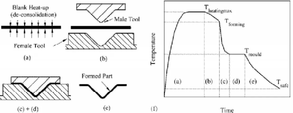
2.6.1 Thermoforming of organic sheets
Organic sheets are continuous fibre-reinforced, semi-finished products, embedded in a
thermoplastic matrix. One of the most used matrix is polyamide, apart from other ad-vantages, especially allows a very good adhesion to fibres. First, the organic sheet is
heated to give shape by thermoforming. Subsequently, this product is heated to a
tem-perature close to the fusion point of the matrix and immediately afterwards, is placed in
a mould and is compressed into shape. Here, it must be ensured that there are no dis-locations of the fibre layers. The entire cycle can last about 60 seconds conceivable for
the quick processing potential of thermoplastics. [RAR12]
Figure 2.12 characterizes the process in terms of physical shape change and thermal variation of the blank during the complete process.
Fig. 2.12: Key stages in the thermoforming process for reinforced thermoplastic
com-posites. [RAR12]
2.6.2 Resin transfer moulding
It is the process of producing composites in a mechanically closed rigid mould. Dry reinforcement (glass fibre, carbon fibre, aramid, etc.), is positioned between the two
A thermosetting resin is injected, often by the central part of the mould, directly in the
reinforcement fibre bundle. The mould is filled by the effect of the hydraulic pressure generated by the injection machine. The mould has normally outputs at the corners,
allowing air from the inside to escape and being replaced by the resin.
Vacuum resin transfer moulding (VRTM) is a variant of RTM which principal difference is that makes use of the atmospheric pressure as help to close the mould, in contrast to
the heavy locking systems used in RTM. [VI17]
2.6.3 Thermoforming and injection moulding
It is a process that combines the thermoforming and subsequent compression with plastic injection. This is a process used by the “Institut für Textiltechnik Augsburg” (ITA) with an Engel 1050H 200 machine.
In an automated cell, individual organic sheets are pre-heated by an infrared oven, inserted into an injection mould by means of a robot with hydraulic needles. It is then
compressed and back-injected with ribs. In figure 2.13 you can see a diagram
illustrating this process. [Kra17]
The use of injection molding also makes it possible to work in thermoplastic with long
fibre reinforcement and thus to achieve components with greater strength. The high
pressure with which the melt is initiated, permits that possible imperfections in the composite sheet can be filled. [PT12]
Fig. 2.13: Step process
of thermoforming combined with injection moulding
.[Kra17]
1. Pick up insert
2. Preheat insert
3. Transfer to mould 4. Thermoforming
5. Back injection
3
Production process
As it was mentioned in paragraph 2.6.3 the production process of parts consists of
several steps. In the first place, preforms, which are the raw material for the process, are obtained. This preforms consist of the union of different layers of nonwoven. This
union is possible by submitting the layers to heat and pressure with a stamping
ma-chine.
Later, these preforms are heated to the melting point of the matrix in an induction
fur-nace. When they reach the melting temperature, a robot transports them to the mould
holding them by the top via a needle group.
Then the mould is closed and the press allows the preform to get the mould’s shape. At this time, the injection unit injects plastic on the low side of the mould culminating the
thermoforming and injection moulding entire process.
Finally, the press opens allowing collecting the final composite piece and ending a
pro-cess cycle.
The process described above is schematically represented in Figure 3.1:
Fig. 3.1: Top view of the manufacturing process. [Ege17]
Infrared oven
Protection zone
Tempering unit
Injection unit
Filling hopper
Robot Tool control panel
3.1
Infrared oven
This is an element of great importance because it provides the necessary heat to melt the preform before introducing it into the mould.
The handling system leaves the preform on a tray. Then the tray retracts back into the
oven where the fusion of the thermoplastic material takes place. After that the tray ex-tends out of the oven and the preform is seized by the handling system and placed in
the mould.
The temperature of the oven is a parameter that influences in the superficial quality of the final piece and therefore, will be dealt with in detail further on.
Figure 3.2 shows the oven employed in the experiments and its principal components.
1) Infrared oven
a) Left oven
b) Right oven 2) Pyrometer
3) Sliding table 1 (retracted) 4) Sliding table 2 (extended)
5) Organic sheet receptor
6) Holding device
Fig. 3.2: Infrared oven and its components. [EnM16]
3.2
Handling system
The handling system is a robot from the company Stäubli AG, Pfäffikon, Switzerland with an Engel control software for operating. This robot consists of six axes controlled
by servomotors. The acquisition-head is driven by a pneumatic system with
Figure 3.3 illustrates the robot and the movements that
can perform.
At the top a head is fitted which is responsible for holding
the workpiece when the robot is transporting it.
As will be seen later, the handling system has relevance in the thesis since it affects the surface quality of the
workpiece.
A group of needles is responsible for providing the
stabil-ity during movement, getting inside the piece with a cer-tain angle to avoid the gravity effect.
Fig. 3.3: Stäubli robot and its rotation axes. [EnM16]
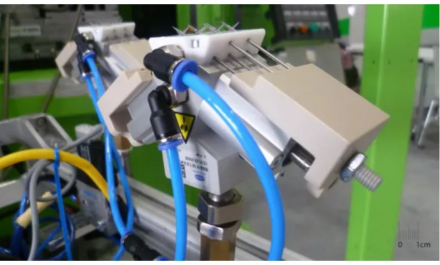
The needle group commented previously is shown in figure 3.4
Fig. 3.4: Image of the needle group in detail (extended position).
There is a second pneumatic circuit which work as a vacuum ejector, since they are used to remove the pressed piece from the mould. This second holding unit is required
because once the moulding process has finished, the final piece is below the melting
temperature of the array and the needles cannot penetrate it.
Fig. 3.5: Image of the second holding system with vacuum circuit.
3.3
Pressing unit
The PRESSING unit is responsible for the injection moulding process. It ensure a tight sealing of lower and upper parts of the mould, holding the injection pressure and
providing the final piece the desired shape.
The upper and lower mould halves can be heated separately. This is necessary to pre-vent a quickly cooling of the molten preform and to allow a good impregnation of the
web with the melted thermoplastic during the compression phase.
Fig. 3.6: Pressing unit opened with the pressing and injection moulds.
3.4
Induction unit
This is an induction equipment composed by an “IFF” generator, together with
water-cooled special inductors, enables the extremely energy-efficient preheating of metallic components in very short times. In the end, the unit is connected to two ferromagnetic
steel plates whose main task is to provide energy in the form of heat to the upper
mould.
This unit allows the possibility to heat the top of the mold without having to elevate the
oil from its interior at high temperatures in which the electrical expenditure is very high
in comparison with the plates whose efficiency is about 75%.
In addition the mould dissipates a lot of energy because it is not isolated from the
environment and it is not viable in terms of energy waste to heat the oil to the desired
temperatures.
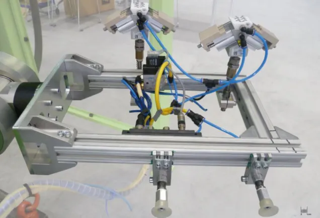
In figure 3.7 an image of the induction plates is presented. The induction plates are
4
Preparation of the experiments
4.1
Objectives
The objective of this thesis is to improve the surface of the pieces obtained through the
thermoforming of web based composites.
There are a large number of factors that influence the final surface of the piece; some of them are fixed parameters in the process, that is, parameters that cannot be
modi-fied as the material of the mould, the atmosphere or the needle group in charge of
holding the piece during its way through the productive process. Others, however, can be modified and it is in them on which we will focus our attention. Some of these are
furnace and mould temperatures, the composition of the web, the introduction of
poly-amide or not, the process employed for obtaining the preform, etc.
Several trials will be held at the beginning in specific segments of the process to
de-termine the influence of certain parameters and to understand how they affect the final
piece.
Subsequently, an experimental design will be applied to certain parameters to
deter-mine which of them affects the final quality of the piece.
Finally, the information collected in the diverse tests will be used to modify the different parameters in order to improve the surface of the final part.
4.2
Preparation of the preforms
The raw material was provided, in the form of nonwoven rolls, by the ITA, which used for its creation a compact non-woven line.
From these rolls, preforms were obtained by cutting the material with the shape of the mould. Subsequently, for the creation of the final web a process recommended by
Mi-guel, whose thesis is about improving the process of obtaining preforms, was followed.
This process consists in the union of four different layers of web using a manual heat-ing press “DEMA Hand-press TP1400” and followed by a coolheat-ing under pressure.
An explanatory flowchart of the process with temperatures, times and weight is shown
Fig. 4.1: Flowchart of the web preparation process.
4.3
First trials
During the early part of the thesis first experiments were carried out to determine the
impact of needle group on the surface of the piece. These experiments were performed
with the help of the robot and the furnace and consisted in the variation of certain pa-rameters in a pre-defined process.
For these first experiments non-woven webs composed of 40% CF 60% PA and
680 g/m2 of density was used.
These parameters were:
- Number of layers of the web
- Different web creation processes
- Temperature of the web surface when leaves the oven
- The insertion of polyamide or not
- The speed of the robot
- The movements of the robot
The predefined process consists of an automatic process in which the robot takes the
piece of a dispenser with the help of the needle group. Afterwards, it carries the web to the furnace where it is heated during a certain time according to the requirements of
the experiment. Finally, after the heating process, the robot takes the piece and carries
it through certain movements to the storage table.
In figure 4.2 a flowchart of the process can be appreciated.
Cutting non-woven material
from the roll
Giving the material the mould shape
Manual heating press 30s 280°C
Cooling under uniform pressure
30s 22,5kg
Formation of a layer (Twice) Manual heating
press 45s 280°C Cooling under
uniform pressure 45s 22,5kg Formation of a
web with two layers (Twice)
Manual heating press 60s 280°C
Cooling under uniform pressure
60s 22,5kg
Formation of a web with four
Fig. 4.2: Flowchart of the segment of the process employed in the first tests.
4.3.1 Parameters of the first experiments
Number of layers of the web: several experiments were carried out varying the number of layers that formed the web. Tests were made from 1 to 4 layers. No more than 4
subjects were used because it has no practical interest in the process, as the mould
does not support thicknesses of more than 4 layers of this material.
Different web creation processes: the duration of the heating with the manual press
and the cooling under pressure processes were also modified in order to obtain
speci-mens of different grade of compaction.
Temperature of the web surface when leaves the oven: this, in particular, is one of the
most significant parameters of the process and is one of those that more attention has
been placed in. Temperatures ranging from ambient temperature to 300 ºC were test-ed.
The insertion of polyamide or not: in some cases a thin layer of additional polyamide
was applied to the surface of the piece in the web obtaining process.
The speed of the robot: the robot's operating speed was also considered as a variable,
which oscillated between 10% and 100% of the maximum possible.
The movements of the robot: two different programs for the robot were used. The first composed of soft movements with the aim of the minor number of external forces
act-ing on the web. And the second, with critical movements in the different axes in which
the web is submitted to diverse forces, the centrifugal ones caused by the rotation on
The robot takes the web from the
dispenser
The robot locates the web above the
oven tray
Retraction of the tray and heating
The needle group holds the heated
web The robot leaves the
web on the storage table
First contact with
the needles
The speed of the robot and
the way it covers are
varia-bles of the experiment
Temperature and times depend on the different experiments
the central axis (forces in y-axis), gravitational forces (z-axis) and air resistance forces
(x-axis).
4.3.2 Conclusions and images of the first experiments
The results were evaluated in terms of the trace’s magnitude that needle group left on the surface of the web.
In general webs formed by 4 layers and with a method of creation as the one specified in paragraph 4.2 had the best results.
As far as the furnace temperature is concerned, the best results were at ambient
tem-perature 21.2ºC, without using the oven. In general, the lower the surface temtem-perature of the workpiece the mark of the needles is lower. However, the process is limited by
the melting temperature of the polyamide, which is 260 ° C and the web must reach at
least this.
After several experiments it can be concluded that the addiction of polyamide
repeatedly improves the final surface.
As far as the speed of the robot is concerned, there are no significant differences in the different webs. However, the marks left by the needles are clearer in the case of high
speeds.
The same happens with the types of movement. In experiments with abrupt movements the holes left by the needles are cleaner and can be better distinguished.
4.3.3 Images of the first experiments
Below are some images of the traces left by the needle group in the webs. All the webs
of the figures are 4 layers based and the creation method is the one specified in para-graph 4.2.
The selected preforms are webs in which most of the parameters are around the
values used in the process. Tempera-tures range from 250 ºC to 300 ºC and in most of the cases the robot speed is the maximum.
The other parameters associated with the images which vary according to the type of
Tab. 4.1: Parameters values of the figures attached.
Figure Tª surface (ºC) Polyamide Speed (%) Movements
4.3 250 No 100 Critic
4.4 300 No 10 Soft
4.5 275 Yes 50 Soft
4.6 225 Yes 100 Critic
4.7 275 Yes 100 Critic
Pictures of the first experiments are shown below. Each one of the divisions of the scale at the bottom of the images is equivalent to 1mm.
Fig. 4.3: Tª of 250 ºC without polyamide with critic movements at 100% speed.
As was mentioned earlier, in processes with critical movements and high speeds the
holes left by the needle group are clearer. This can be contrasted with the holes in the
web shown in Figure 4.4 in which the robot's movements were soft and the speed was
Fig. 4.4: Tª of 300 ºC without polyamide with soft movements at 10% speed.
Fig. 4.5: Tª of 275 ºC with polyamide with critic movements at 50% speed.
This is the first image with a web that has been applied polyamide. Can be seen that
the surface is smoother than the previous ones where carbon fibre threads can still be identified.
Fig. 4.6: Tª of 225 ºC with polyamide with critic movements at 100% speed.
Fig. 4.7: Tª of 275 ºC with polyamide with critic movements at 100% speed.
4.4
Experimental design
One of the most important parts of the thesis is the development of an experimental
design applied to the entire automated process with the aim to determine which of the factors affect the response more. The response will be the roughness of the web sur-face and will be measured with the help of a roughness meter “Mitutoyo SJ-400”.
For this section an experimental design of 3 factors has been prepared, these 3 factors are the composition of the web, the temperature of the surface when the web leaves
temperature of the oil that circulates by its interior plus the heat produced by the
induc-tion plates acting on it.
The temperatures of the web surface and the mould will have 3 levels, that is to say,
there will be a low temperature, an average and a high one despite the fact that the
temperature of the mould will be determined by the time the induction plates act. How-ever, for the composition of the web there will be only two levels, that is, two types of
composition that is polyamide and polyester with 40% CF each of them.
As it is an experiment of 3 factors, two of them with 3 levels and one with 2, 18 trials
must be performed so that the experiment significant is.
Table 4.2 collects the different combination of the diverse factors in all experiments.
Tab. 4.2: Dependent variable combinations in the experiment.
Test Composition Tª oven (ºC) and time (s) Time induction (s)
1 40% CF 60% PA 260 ºC and 80 s 20 s
2 40% CF 60% PA 260 ºC and 80 s 40 s
3 40% CF 60% PA 260 ºC and 80 s 60 s
4 40% CF 60% PA 280 ºC and 80 s 20 s
5 40% CF 60% PA 280 ºC and 80 s 40 s
6 40% CF 60% PA 280 ºC and 80 s 60 s
7 40% CF 60% PA 300 ºC and 80 s 20 s
8 40% CF 60% PA 300 ºC and 80 s 40 s
9 40% CF 60% PA 300 ºC and 80 s 60 s
10 40% CF 60% PET 260 ºC and 80 s 20 s
11 40% CF 60% PET 260 ºC and 80 s 40 s
12 40% CF 60% PET 260 ºC and 80 s 60 s
13 40% CF 60% PET 280 ºC and 80 s 20 s
14 40% CF 60% PET 280 ºC and 80 s 40 s
15 40% CF 60% PET 280 ºC and 80 s 60 s
16 40% CF 60% PET 300 ºC and 80 s 20 s
17 40% CF 60% PET 300 ºC and 80 s 40 s
The density of the materials was 680 g/m2 for non-woven webs composed of 40% CF
60% PA and 212 g/m2 for webs composed of 40% CF 60% PET.
As the density of the raw materials is very different since the polyester nonwoven is 3
times less than the polyamide one, the webs employed will not have the same number of layers because its width would be very different. Therefore, 12 layers will be used to
achieve similarity between the different webs.
An explanatory flowchart of the process with temperatures, times and weight for poly-ester webs is shown in the Figure 4.8.
Fig. 4.8: Flowchart of the polyester webs preparation process.
Cutting non-woven material
from the roll
Giving the material the mould shape
Manual heating press 30s 280°C
Cooling under uniform pressure 30s 22,5kg
Formation of a layer (Twice) Manual heating
press 45s 280°C Cooling under
uniform pressure 45s 22,5kg Formation of a
web with two layers (Twice)
Manual heating press 60s 280°C
Cooling under uniform pressure 60s 22,5kg
Formation of a web with four
layers (3 Times)
Manual heating press 75s 280°C
Cooling under uniform pressure 75s 22,5kg Formation of a
web with eight layers Manual heating
press 90s 280°C Cooling under
uniform pressure 90s 22,5kg
4.5
Parameters of the process
As it is an automated process with peripheral units such as oven, press and injection unit there are a large number of parameters in the process.
4.5.1 Temperature
Temperature is one of the most important parameters of the process as it is present in the oven and the moulds. In experiments the temperature varies both in the oven and
in the mould. This parameter is also present in the refrigeration flow of induction plates
which has a value between 20 ºC and 21 ºC.
4.5.2 Pressure
This is another parameter with great importance as it is present in the press, the robot,
the furnace and the refrigeration flow of the induction plates.
The overall set of the machine has compressed air ducts that allow the opening and closing of the oven as well as the movements of robot and needle group respectively.
The unit providing the cooling flow of the induction plates operates at a pressure
be-tween 3 and 4 bar.
Finally, this parameter is represented in the force exerted by the press on the surface
of the web. This force is 2000kN on an approximate surface of 35 cm2 which results in
5,7·108 Pa.
4.5.3 Time
This parameter is present in the cycle time of the robot, the heating time in the oven,
the time that the induction plates act and the compression time of the press.
The heating time in the oven remains constant in all the process and is 80 seconds whereas the time the induction plates act varies between 20 and 60 seconds.
The duration of the press process is 30 seconds approximately. Of those 30 seconds
25 correspond to the compression process while the rest are distributed in the closing and opening of the moulds and the movement of the cores.
Since the Start button is pressed until the robot returns home the duration of a full cycle
is 1 minute 50 seconds.
Fig. 4.9: Flowchart of the automated process cycle done by the robot.
4.5.4 Press parameters
In addition to temperature, time and pressure there are also parameters of the different
peripheral units. This is the case of the press in which other variables are also involved
as the closing speed of the mould, which at the beginning is 385 mm/s and decreases
when the upper and lower part of the mould are close.
The speed and the force related to distance are represented in Figure 4.9.
Fig. 4.10: Representation of speed (mm/s) and force (kN) versus distance (mm).
However, the force remains constant during the closing period and grows as both
moulds approach until they come in contact reaching a value of 2000 KN. Takes a web from
the dispenser
Locates the web above the oven
tray
With the induction plates heats the upper part of the
mould Takes the heated
web from the oven to the mould Carries the final
piece to the table
The last relevant parameter of the press is the mould closing position which has a
val-ue between a third and a half of the web thick. If the mould closing valval-ue does not reach this number the mould will not close well and the experiments will not be valid.
4.5.5 Induction unit
The induction unit has a set of parameters characteristic of its internal method. These
are detailed below with their respective operational values:
- Root mean square intensity (Irms) 53-55 A
- Root mean square voltage (Urms) 450-460 V
- Intensity 13,5-13,7 A
- Frequency 10,0 kHz
5
Evaluation and statistical study
In the table below, roughness values of different areas are collected. In each web three
different measures have been done. The first measure corresponds to the average surface roughness and was taken from a random point in the middle of the piece. The
second and the third measures were taken over the area in which the needle group
acted.
Several values of parameter Ra (Roughness average) were collected. Ra is the
arith-metic average of the absolute values of the roughness profile ordinates, parameter
which gives a good general description of the height variations in the surface.
Tab. 5.1: Roughness average values from different zones of the tested webs.
Web Average
rough-ness (µm)
Roughness nee-dle zone left (µm)
Roughness needle zone right (µm)
Roughness value (µm) 40 % C F 60 %PA
1 27,58 36,12 32,77 6,87
2 26,76 28,40 30,00 2,44
3 24,29 37,86 29,78 9,53
4 13,52 35,75 27,75 18,23
5 21,16 24,17 27,25 4,55
6 15,25 25,21 27,26 10,99
7 15,27 29,95 40,23 19,82
8 15,32 40,62 28,33 19,16
9 11,33 22,03 33,39 16,38
40 % C F 60 %PE T
1 12,16 8,79 14,58 0,48
2 11,92 9,86 13,68 0,15
3 13,21 14,11 11,05 0,63
4 10,26 8,85 8,77 1,45
5 17,31 20,47 24,31 5,08
6 11,67 8,29 12,13 1,46
7 7,88 11,73 13,23 4,60
8 6,01 14,81 21,47 12,13
The roughness value is the response in the experimental design. It comes from doing
the arithmetic mean of the roughness values of the needle zones and subtracting the average roughness.
Once all the variables of the experimental design are defined, we proceed to perform a variance analysis with “Statgraphics XVII”.
In the Table 5.2 appears the ANOVA table for variable Roughness.
Tab. 5.2: ANOVA table for variable Roughness, type III Sums of Squares.
Source Sum of Squares Df Mean Square F-Ratio P-Value
A:Tª oven 276,976 2 138,488 21,05 0,0075
B:Time induction 6,52301 2 3,26151 0,50 0,6422
C:Material 328,363 1 328,363 49,91 0,0021
AB 60,295 4 15,0738 2,29 0,2209
AC 21,1795 2 10,5898 1,61 0,3070
BC 77,1613 2 38,5807 5,86 0,0647
RESIDUAL 26,3154 4 6,57886
TOTAL 796,813 17
All F-ratios are based on the residual mean square error.
The ANOVA table decomposes the variability of Roughness into contributions due to various factors.
The P-values test the statistical significance of each of the factors. Since 2 P-values (Material and Tª oven) are less than 0,05 (significance level), these factors have a
sta-tistically significant effect on roughness at the 95,0% confidence level. This means that
with a safety of 95,0% can be assured that variable roughness depends directly on the oven temperature and on the material employed.
Moreover, as this P-values are less than 0,01 the material and Tª oven effect on
roughness can be affirmed with 99,0% of confidence level.
However, the P-value of the induction time is 0,6422 greater than the significance level,
so there is not enough evidence to reject the null hypothesis that the effect (induction
time) does not affect to the response (roughness).
This means that the null hypothesis cannot be rejected, but not for that reason can be
assumed that the null hypothesis is true, simply it cannot be determined.
In Figure 5.1 a graphical ANOVA for Roughness can be appreciated.
Fig. 5.1: Graphical ANOVA for Roughness.
Residuals
Temperature oven 260 280 300 P = 0,0075
Time induction P = 0,6422
40 60
20
Material PE PA P = 0,0021
Graphical ANOVA for Roughness


![Fig. 2.7: Stress-position depending on the length of the fibre. [CR14]](https://thumb-us.123doks.com/thumbv2/123dok_es/6161227.182274/23.892.164.778.463.672/fig-stress-position-depending-length-fibre-cr.webp)

![Fig. 2.11: Diagram of Dilo system for nonwoven production. [Mar17]](https://thumb-us.123doks.com/thumbv2/123dok_es/6161227.182274/28.892.150.806.887.1116/fig-diagram-dilo-nonwoven-production-mar.webp)
![Fig. 3.1: Top view of the manufacturing process. [Ege17] Infrared oven](https://thumb-us.123doks.com/thumbv2/123dok_es/6161227.182274/31.892.146.800.565.1010/fig-view-manufacturing-process-ege-infrared-oven.webp)