Universitat Politècnica de Catalunya
Departament d’Enginyeria Química
Ph.D. Thesis in
ELECTRON TRANSFER
PROCESSES IN BIOMIMETIC
MEMBRANES INCORPORATING
PRENYLQUINONES
Javier Hoyo Pérez
Supervisors
Prof. Joan Torrent Burgués
Ph.D. Ester Guaus Guerrero
INDEX
Chapter
1
Motivation
and
Objectives
1
1.1 Motivation 3
1.2 Objectives 5
Chapter
2
Fundamental
techniques
7
2.1. Methods for preparing supported biomimetic membranes 8 2.1.1 Langmuir and Langmuir-Blodgett techniques 9
2.1.1.1 Langmuir monolayer formation 10 2.1.1.2 Basics of the Langmuir films technique 10 2.1.1.3 Surface Pressure measurements 11 2.1.1.4 Surface Pressure – Area Isotherms 15 2.1.1.5 Langmuir π-A isotherms experimental information 18 2.1.1.6 Langmuir-Blodgett Technique 24 2.1.1.7 LB films special features 28 2.1.2 SPB technique by vesicle fusion 30 2.1.2.1 Vesicles preparation 30 2.1.2.2 Vesicle fusion method for SPB formation 31 2.1.3 Differences between the biomimetic membranes formed
using each method 35 2.1.4 Limitations of biomimetic membranes 37 2.2 Molecules and substrates used for biomimetic membranes preparation 39 2.2.1 Amphiphilic molecules in biomimetic membranes 39 2.2.2 Substrate relevance for preparing biomimetic membranes 39
2.2.2.1 Substrates used in this Ph. D. Thesis 41
INDEX
II
2.3.2 AFM and related techniques 46 2.3.2.1 Topographic modes 47 2.3.2.2 Force Spectroscopy 48 2.4. Voltammetric technique 53
2.4.1 Electrode processes 53 2.4.2 Voltammetry set up 54 2.4.3 Linear and cyclic voltammetry 55 2.5 References of Chapter 2 60
Chapter 3 Biomimetic membranes and its components
71
3.1 Biological Photosynthesis 73 3.1.1 Photosynthesis localization 73 3.1.2 Photosynthesis process 73 3.2 Biomimetic membrane models 75 3.2.1 Biomimetic membrane characteristics 76 3.2.1.1 Physical states 76 3.2.1.2 Effect of chain length, unsaturations and headgroup
in the compactness of the biomimetic membrane 80 3.2.1.3 Fluidity 80 3.2.1.4 Defects formation 81 3.2.2 Interactions substrate-electrolyte-membrane 81 3.2.2.1 Electrolyte layer 81 3.2.2.2 Capacitance 84 3.3 Lipids used for biomimetic membrane formation 84
3.3.1 DPPC 85
3.3.1.1 DPPC physical states 85 3.3.1.2 Bilayer response to potential variations 86 3.3.2 MGDG and DGDG 87
III
3.4 Biological electron and proton shuttles 93 3.4.1 Quinones 93
3.4.1.1 Ubiquinones 93 3.4.1.2 Plastoquinones 95 3.4.2 Position of UQ or PQ molecules in the biomimetic membrane 95
3.4.2.1 Diving quinone 96 3.4.2.2 Swimming quinone 98 3.4.2.3 UQ pools and aggregates 99 3.4.2.4 Ubiquinone molecules with different tail length 100 3.4.3 Quinone interactions with the lipid matrix. 101
3.4.4 Quinone redox mechanisms 102 3.4.4.1 Buffered aqueous solution 103 3.4.4.2 Unbuffered aqueous solution 105 3.4.4.3 Aprotic solution 106 3.4.4.4 Aprotic solution with water added 107 3.4.5 Quinone electron transfer in lipid biomimetic membranes 107 3.4.6 Techniques used for preparing confined quinones on
conductive substrates and their eletrochemical study. 111 3.4.7 Relevant processes that experiences PQ and UQ in biological
membranes 112
3.4.7.1 Electron transfer 112 3.4.7.2 Diffusion 112 3.5 References of Chapter 3 114
Chapter 4 Materials and
Methods 133
4.1 Materials 134
4.2 Methods 134
INDEX
IV
4.2.4 Force curves 136 4.2.5 Brewster angle Microscopy (BAM) 136 4.2.6 Electrochemical characterization 136
Chapter
5
Results
and
Discussion 139
5.1 UQ system 141 5.1.1 π-A isotherms and physical states 141
5.1.2 AFM 143
5.1.3 Electrochemical behaviour 144 5.1.4 Global sight of the UQ system transferred on ITO using the
LB technique 152 5.2 PQ system 153 5.2.1 π-A isotherms and physical states 153
5.2.2 AFM 155
5.2.3 Electrochemical behaviour 156 5.2.4 Global sight of the PQ system transferred on ITO using the 162
LB technique
5.3 DPPC 163
5.3.1 π-A isotherms and physical states 163
5.3.2 AFM 164
5.3.3 Electrochemical behaviour 166
5.4 MGDG 168
5.4.1 π-A Isotherms and physical states 168
5.4.2 AFM 171
5.4.3 Electrochemical behaviour 175
5.5 DGDG 177
5.5.1 π-A isotherms and physical states 177
5.5.2 AFM 180
5.5.3 Electrochemical behaviour 183 5.6 MGDG:DGDG (2:1) (MD) 185 5.6.1 π-A isotherms and physical states 185
V
5.6.3 Electrochemical behaviour 192
5.7 DPPC:UQ 194
5.7.1 π-A isotherms and physical states 194 5.7.2 Thermodynamic study 197 5.7.3 AFM 200
5.7.4 Electrochemical behaviour 213 5.7.5 Global sight of the DPPC:UQ system transferred on a
substrate using the LB technique 215 5.7.6 ITO-DPPC:UQ biomimetic system studied using SPB technique 219 5.7.6.1 Topography and mechanical properties 219 5.7.6.2 Electrochemical characterization 225 5.7.6.3 Global sight of the DPPC:UQ system deposited by SPB 229
5.8 MGDG:UQ 231
5.8.1 π-A isotherms and physical states 231
5.8.2 BAM 235
5.8.3 Thermodynamic study 236 5.8.4 AFM 238
5.8.5 Electrochemical behaviour 243 5.8.6 Global sight of the MGDG:UQ system transferred on ITO
using the LB technique 253
5.9 MGDG:PQ 258
5.9.1 π-A isotherms and physical states 258
5.9.2 BAM 262
5.9.3 Thermodynamic study 263 5.9.4 AFM 265
5.9.5 Electrochemical behaviour 270 5.9.6 Global sight of the MGDG:PQ system transferred on ITO
INDEX
VI
5.10.5 Electrochemical behaviour 295 5.10.6 Global sight of the DGDG:PQ system transferred on ITO
using the LB technique 305
5.11 MD:PQ 309
5.11.1 π-A isotherms and physical states 309 5.11.2 Thermodynamic study 313 5.11.3 AFM 315
5.11.4 Electrochemical behaviour 321 5.11.5 Global sight of the MD:PQ system transferred on ITO
using the LB technique 329 5.12 Global sight of the galactolipid and galactolipid:quinone systems 334 5.13 References of Chapter 5 344
Chapter 6 Conclusions
357
Appendix
A:
Symbols
and
acronyms
361
Appendix
B:
Selected
publications
367
Appendix
C:
Resum
en
català
369
VII
STRUCTURE
This Ph. D. Thesis studies the electron transfer process that takes place in photosynthesis using biomimetic membranes. The complexity of this biomimetic membrane increases according to the lipids and quinones that compose it, beginning from model lipids and ending with the use of a lipid mixture that represents the 70% of the natural lipid content. So that, this Ph. D. Thesis presents studies of several biomimetic systems, which have a similar State of the Art and also a similar discussion, so that, I have decided to present the Ph. D. Thesis as a large scientific journal in which the State of the Art and the Materials and Methods chapters involve all the studied systems and techniques. On the other hand, the Results and Discussion chapter is divided in sections, and each of them presents the results and their corresponding discussion of each system. Finally, the conclusions obtained from each system are summarized in the Conclusions Chapter.
Chapter 1 defines the objectives and motivation of this Ph. D. Thesis.
Chapter 2 explains the techniques used in this Ph. D. Thesis for biomimetic membrane preparation and characterization, in order to understand the basis of them and their applications to the systems studied, without exposing the full mathematical background of the different techniques. Moreover, the mathematical expressions for the experimental results treatment are also exposed.
STRUCTURE
VIII
Chapter 4 exposes the chemicals and the instruments that we have used.
Chapter 5 presents the results and discussion divided in three blocks. The first involves the two quinones that we use in our studies. The second block corresponds to the pure lipids used and the third block explains the lipid-quinone systems. The last section gives a global sight of the galactolipid and galactolipid:quinone systems.
Chapter 6 exposes the conclusions obtained from the different systems studied achieving a general vision of the quinone position in the lipid matrix and the redox processes that influence it.
Chapter 1
Motivation and Objectives
Most of the actions we perform in our way of life require energy. Since we stand up we use electricity for clock alarm, for heating the shower water, for bread toasting... We use fuel for work travelling and electricity for the computer and other electronic devices we use in our work time. We use electricity for leisure, lighting and heating. The energy we consume is present in different forms electricity, gas or fuel. Electricity is the most used and its sources can be fossil like: gas, fuel, coal and nuclear, or renewal, like: solar, wind, geothermic… Fossil sources have several inconvenients, specially that they are finite and the pollution they produce. On the other hand, renewal sources have the inconvenience that energy must be used at the time it is produced.
CHAPTER 1. MOTIVATION AND OBJECTIVES
2
The photosynthesis in higher plants takes place in the thylakoid membrane that is a lipid bilayer composed mainly by galactolipids, being the most important monogalactosyl diacylglycerol, MGDG (≈ 50%), and digalactosyldiacylglicerol DGDG (≈ 25%). Plastoquinone (PQ) molecules are placed between both leaflets of the bilayer acting PQ as the electron and proton shuttle from the Photosystem II (PSII) to the cytochrome b6f.
MOTIVATION 3
scientists have performed several experiments on the photosynthetic process changing artificially some variables to evaluate its response. The first time that the concept artificial photosynthesis appears, is in 1962 in a NASA document titled Applied research concerning artificial photosynthesis. The artificial phostoynthesis remains with low interest until 1978.
After the 1973 oil crisis, scientists saw the opportunity that artificial photosynthesis represents. The science interest on this field grew till the Great Recession of 2007 when the interest increased exponentially until nowadays.
The photosynthetic process involves three main steps: light absorption, electron transfer and energy production. Each step is complex and implies several variables, so the access to the complex functioning of biological photosynthetic membranes is a real challenge, in consequence, researchers have focused their efforts in studying only one of these steps.
1.1 Motivation
My Ph.D. career began in 2007 when I finished my Degree Project in Chemical Engineering in the Technische Universität Berlin (TUB). There, I was offered to study my Ph. D. Thesis in a biotechnological field, but Prof. Fausto Sanz in collaboration with Prof. Joan Torrent offered me the possibility of studying the photosynthesis and I enrolled. Prof. Fausto Sanz is the group leader of the nanoprobes and nanoswitches group in the Institute for Bioengineering of Catalonia (IBEC) and he is also Professor of electrochemistry at the University of Barcelona. On the other hand, Prof. Joan Torrent and Ph. D. Ester Guaus are group leaders of the Laboratory of Molecular Electrochemistry, Interfaces and Nanometric Films (LEIPN) group at Universitat Politècnica de Catalunya, where both leaders teach nanometric techniques.
CHAPTER 1. MOTIVATION AND OBJECTIVES
4
duroquinone (DQ), that is a more hydrophobic redox molecule than BQ, in order to avoid the solubilization of quinone in the aqueous electrolyte solution. These results were presented in the Master Thesis of Chemical Processes studied at the UPC and part of them was also published in the first volume of Avances de la electroquímica en Iberoamérica, Portugal y España. The use of DPPC and quinones, which are not present in natural
photosynthetic membranes, is explained thanks to the widely knowledge of these molecules and the low economical cost of them. These reasons allow us to perform many experiments to adapt the several techniques used in this Ph. D. Thesis to work with more complex molecules. We also designed a new glass cell and the architecture of its supports, to adapt them to both the low concentrations that we would use and also the rectangular shape of the ITO working electrode.
The Ph. D. Thesis content began studying SPBs and LB films of DPPC inserting ubiquinone (UQ) that is a molecule similar in shape and size to PQ, having the former ten times lower economical cost. These experiments worth to realize that the reproducibility of the SPBs when using this kind of systems is lower than the obtained with the LB films transferred on hydrophilic substrates, so from this point, we only worked using the LB technique. Next step was studying UQ with the lipid most present in natural photosynthetic membranes (MGDG). The initial idea of working with UQ was using it as a prior step to work with the natural present PQ, but its results were of great relevance, so finally we spent a couple of years working with UQ. After that, we prepared MGDG films inserting the PQ and we continued studying DGDG films inserting PQ. The last step has been increasing the difficulty and the reliability of the model preparing a mixture of MGDG and DGDG (MD) inserting also PQ, which represents ca. 70% of the lipidic content of natural cell membranes and implies a leap on the study of these systems. Part of the results of this Ph.D. Thesis have been already published in prestigious indexed international scientific journals of this field.
OBJECTIVES 5
1.2 Objectives
The main target of this Ph.D. Thesis is the knowledge of the electrochemical processes that take place in a biomimetic membrane and the position of the quinone molecules in the galactolipid matrix simulating several conditions that can be applied to artificial photosynthesis. We were aware of the ambitious objective of preparing biomimetic membranes using the natural present components, so that, we prepared a timeline according to that. Obviously, an accurate preliminary electrochemical characterization of simple quinone (BQ or DQ) in solution using several working electrodes was required to check our results with the little literature that there is on this field. Therefore, choosing the best experimental conditions and adapting the experimental set up to work with these systems using, as substrate, indium tin oxide glass slides (ITO), which has good electrical and optical features.
Once the techniques were adapted, the next step was working with natural present components, increasing at each step the work difficulty, achieving to mimic conditions close to that of a natural membrane at the end of this Ph. D. Thesis. The final results of these experiments show that the MD monolayer establishes a correct environment to embed the PQ molecule and permits its redox activity using ITO.
The objectives of these Ph. D. Thesis involve:
• The formation of mono- and bilayers of DPPC and DPPC:UQ mixtures on solid substrates using, respectively, the LB and vesicle fusion technique. The characterization of these films will permit the evaluation of the film reproducibility depending on the preparation technique.
CHAPTER 1. MOTIVATION AND OBJECTIVES
6
• The formation of monolayers using the Langmuir technique of pure quinones (UQ and PQ), pure lipids (DPPC, MGDG, DGDG and MD) and the selected lipid: quinone mixtures at the air-water interface. The study of these monolayers will indicate the physical state and the mixing behaviour in the mixtures case.
• The monolayers described will be transferred on mica and, using AFM, the topography and the height of the transferred monolayers will be characterized. This characterization permits obtaining both the compactness and the physical state of the monolayer on a solid substrate.
• The described monolayers will also be transferred on ITO, and using cyclic voltammetry, their successful transfer on this conductive and hydrophilic substrate and their electrochemical response will be evaluated.
Chapter 2
Fundamental techniques
As it has been stated in the Objectives section, the main target of this Ph.D. Thesis is the understanding of the redox processes in biomimetic membranes for a further use in artificial photosynthesis. This target can be classified as part of the nanobioengineering due to requires controlled elaboration of nanoscale systems and, so that, request the use of nanoscale resolution techniques. Natural photosynthesis takes place in the cell membrane that is a selectively permeable lipid bilayer. It is composed of a variety of biological molecules being the most important lipids and proteins. Both are primarily responsible for membrane function, as well as structure, and interact between them. So that, the techniques for studying biomimetic membranes (membranes that mimic the biological ones) must consider the structure formed and the interaction between the different components.
In this chapter, I will present the techniques that we have used in this Ph.D. Thesis to prepare and characterize biomimetic membranes. The techniques are exposed and explained to understand the basis of them and their applications to the systems studied, without exposing the full mathematical background of the different techniques.
CHAPTER 2. FUNDAMENTAL TECHNIQUES
8
The use of LB technique offers an accurate control of the transferred monolayer, resulting in a higher reproducibility, especially in substrates with nanometric roughness like indium tin oxide (ITO). We have also used the vesicle fusion technique to prepare supported planar bilayers (SPB). This technique has been improved by us to achieve a good reproducibility in nanometric roughness substrates, but the precise film stage deposition achieved with the LB technique made us to prepare the major part of the biomimetic membranes using this technique.
The second section (Section 2.2) exposes the molecules and the substrates used, and the third section (Section 2.3) explains the different techniques used for the characterization of the biomimetic membranes. The cyclic voltammetric (CV) technique is presented in a separated section (Section 2.4) due to it has not been only used to characterize the quality of the biomimetic membrane. In this Ph. D. Thesis, CV is mainly performed to study the electron transfer processes.
2.1. Methods for preparing supported biomimetic membranes
Supported biomimetic membranes can be prepared using several procedures. The most used are vesicle fusion and Langmuir-Blodgett (LB) or a combination of LB+Langmuir-Schaefer (LS) transfer. The vesicle fusion and LB technique are explained in depth in the following sections due to they are used in this Ph. D. Thesis.
METHODS FOR PREPARING SPB 9
properties but they have the inconvenience of not having a water layer between the monolayer and the substrate, so the fluidity of the biomimetic membrane is reduced [1[2[3]. t-BLM is similar to SAM using the former a thiolipid instead of a thiol to form the first leaflet, and preparing a mono- or bilayer on this first leaflet [4]. Recently, Mach et al. [5] have developed a potential driven formation of SPB achieving a SPB more stable against electrical and mechanical perturbations than using other SPB preparation techniques. In this section we explain only the used techniques.
Compared with other techniques for preparing biomimetic membranes, the techniques that use solid supports (in this Ph. D. Thesis SPB and LB) have an important advantage with the increase in robustness and stability. Moreover, the formation on this support permits using analytical techniques like AFM, quartz crystal microbalance, surface plasmon resonance, ellipsometry…On the other hand, the main disadvantage is that transmembrane proteins can not be placed in the formed SPB or LB due to the interaction with the substrate. As a result, some authors have proposed SAMs to establish a height difference between the substrate and the SPB with transmembrane protein inserted.
2.1.1 Langmuir and Langmuir-Blodgett techniques
LB technique allows building up lamellar lipid stacking by transferring onto a solid support a monolayer (Langmuir film) previously formed at the air|water interface. Langmuir films of lipid molecules have been extensively used as models to understand the role and the organization of biological membranes and to improve the knowledge about the molecular recognition process [6]. LB films present multiple applications ranging from signal transducer and nanobiocatalysis in biomimetic situation to its use in bioelectronics and nanobiosensors. Moreover, LB technique has shown its increasing relevance in drug vectorisation and drug delivery [7].
CHAPTER 2. FUNDAMENTAL TECHNIQUES
10
2.1.1.1 Langmuir monolayer formation
Langmuir films are based on the properties of certain organic molecules like lipids to orient themselves at the air|water interface between the gaseous and the liquid phase. The Langmuir monolayer is considered an extreme case of adsorption to interfaces with all the spread molecules concentrated at the interface [7]. Most of the molecules capable to form Langmuir films are insoluble amphiphilic molecules, also known as amphiphiles, composed of two main regions being a hydrophilic headgroup (head) and a hydrophobic tailgroup (tail).
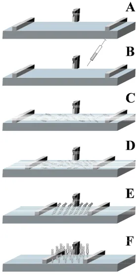
The first step for obtaining a Langmuir film is preparing a solution of the amphiphilic molecules in a solvent with the following characteristics: non-polar, volatile, water-immiscible and chemically stable. The second step involves pouring the subphase in the trough. The trough is a PTFE container with a swimming pool shape, so having a very large 2D surface and short depth. This container has also one or two PTFE movable barriers controlled by a computer (Figure 2.1A). The third step consists on placing drops of the previously prepared solution onto the subphase (Figure 2.1B). It results in molecules spreading over the entire available area due to the intermolecular forces. After some minutes for solvent evaporation, thanks to the self assembly nature of the molecules, a monolayer has been formed (Figure 2.1C) at the interface with the headgroups immersed in the subphase and the tails remaining outside, pointing towards the gas phase. This orientation is achieved to minimise their free energy. Then, the movable controlled barriers compress the film achieving the different phase stages (Figures 2.1D-F) that will be explained in the following sections.
2.1.1.2 Basics of the Langmuir films technique
The thermodynamic properties of the air|liquid interface drive the formation of an amphiphilic molecules monolayer. There is an excess of free energy in the liquid surface compared with the liquid bulk due to the different environment.
METHODS FOR PREPARING SPB 11
interface has a larger attraction towards the liquid than the gas phase, obtaining an attractive force towards the bulk so minimizing the air|water interface area. The interaction between water surface molecules and the polar group of the amphiphile implies a reduction of the free energy of the system and, in consequence, the expansion of the air|water interface. In this situation, a force arises between the liquid molecules (cohesion), which depends on the substance properties.
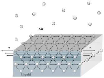
The line force acting on the surface molecules is the surface tension γ (Figure 2.2). In the case of water its value is high (72.8 mN·m-1 at 20˚C) owing to the strong intermolecular
forces. The surface tension of a flat interface can be described by the Expression 2.1 [9,10] where S is the area of the subphase surface and F and G are respectively the Helmholtz and the Gibbs free energies of the system. Keeping constant the temperature T, volume V or pressure P and amounts of all components ni.
ni P T ni V T S G S F , , , , ⎟ ⎠ ⎞ ⎜ ⎝ ⎛ = ⎟ ⎠ ⎞ ⎜ ⎝ ⎛ = δ δ δ δ
γ Expression 2.1
In the case of a pure liquid that is in equilibrium with its saturated vapour at the flat interface, Expression 2.1 can be simplified in Expression 2.2 where FS refers to the surface
excess free energy.
S FS
=
γ Expression 2.2
2.1.1.3 Surface Pressure measurements
The attractive interactions of the water molecules at the interface are lowered when the amphiphilic molecules accumulate at the air|liquid interface. So that, some authors has classified the surface tension as a negative pressure [7]. The surface tension remains invariable while the amphiphile concentration per area unit is low. Increasing the amphiphile concentration per unit area (closing the barriers), a reduction of the intermolecular distances occurs, thus lowering the surface tension. Surface pressure is the difference between the surface tension of pure subphase (γ0) and the surface tension of the
subphase with the presence of amphiphile (γ1). This is a force per length unit, although it is
called pressure (Expression 2.3) in analogy with a force in a two dimensions model. 1
0 γ
γ
CHAPTER 2. FUNDAMENTAL TECHNIQUES
12
[image:22.595.144.425.167.722.2]The Wilhelmy plate is the most used method for experimentally measuring the surface pressure during the monolayer compression because of its simplicity and its uses for experimentally surface tension measurement.
METHODS FOR PREPARING SPB 13
Figure 2.2. Surface tension scheme at the air|water interface.
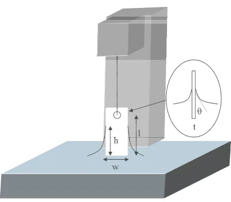
The Wilhelmy plate method quantifies the absolute force exerted on a platinum sheet or a chromatography filter paper plate partially immersed in the subphase (Figure 2.3). The surface tension is measured in the pure subphase before the amphiphile is added and after this addition. The difference between both surface tensions is then converted to surface pressure.
Expression 2.4 correlates the F0 (net downward force) with the surface tension of the
subphase, being L the plate length, w the width and t the thickness. ρp is the material
density and h is the height of the plate immersed in a liquid of density ρL, g the gravitational
constant, θ0 the contact angle of the liquid with the solid plate [6].
gtwh w
t gLwt
F0 = ρp +2γ0( + )cosθ0 −ρL Expression 2.4
Similar equation (Expression 2.5) is obtained for the monolayer when it has been spread on the subphase, being θm the contact angle of the liquid covered by the monolayer on the solid
plate and Fm the force exerted on the plate.
gtwh w
t gLwt
CHAPTER 2. FUNDAMENTAL TECHNIQUES
14
The Wilhelmy plate measures the change of the force exerted in the presence of the monolayer maintaining h constant, following the Expression 2.6.
) cos cos
)( (
2 1 0 0
0 = + γ θ −γ θ
− =
ΔF Fm F t w m Expression 2.6
As we can affirm that t<<w and considering the plate completely wetted, then, the contact angle becomes zero, the change in force can be expressed as in Expression 2.7. The perfect wetting is only achieved when the plate is freshly cleaned prior to being immersed. This is the principal limitation of the Wilhelmy method.
γ γ
γ − = Δ
=
[image:24.595.167.400.365.569.2]ΔF 2w( 1 0) 2w Expression 2.7
Figure 2.3. Surface pressure measurement scheme using the Wilhelmy Balance.
Introducing the surface pressure concept, the Expression 2.7 can be also expressed as follows:
w F
2
Δ − = Δ −
= γ
METHODS FOR PREPARING SPB 15
2.1.1.4 Surface Pressure – Area Isotherms
The surface pressure (π)-Area (A) isotherm is the plot of the surface pressure change as a function of the area available for each molecule on the subphase surface at constant temperature (Figure 2.4). This π-A isotherm represents a fingerprint of the monolayer in the subphase conditions used.
The π-A isotherm quantify the surface pressure while the barriers are continuously compressing, so changing the total covered area. When compressing, the hydrophilic and hydrophobic parts of the molecule drives the whole molecule orientation. In this process, the number of molecules in the subphase surface is maintained and the area is reduced (closing barriers), then the area per molecule is reduced. The forces that origin the different physical state (phases) are the interaction forces between the molecules of the film and between the film and the subphase. The interactions between molecules of the film depend on the van de Waals forces between the hydrocarbon chains and the forces between the headgroups, whereas the interactions between the film molecules and the subphase depend on the attraction-repulsion forces between them.
The first appearing phase is gas phase (G) and appears at low concentration of amphiphiles per unit area, causing a very low surface pressure (π < 0.5 mN·m-1). Increasing the compression, three phases can be observed (not all always present), liquid expanded (LE), liquid condensed (LC) and solid (S). These phases correspond to different molecular organization in which the molecules have different degrees of freedom.
The phase change can be identified in the π-A isotherm as discontinuities of the isotherm whereas the plateaus are associated with enthalpy changes in the monolayer [6]. The initial phase (G) is characterized by large distance between molecules, so the intermolecular forces are small and have no lateral adhesion. So that, having little effect on the free energy of the aqueous subphase. As the gaseous phase is compressed, the hydrocarbon chains start to lift away from the air|water interface (Lift-off point) due to the weakness of interactions between the tailgroups and the subphase.
CHAPTER 2. FUNDAMENTAL TECHNIQUES
16
[image:26.595.81.494.172.476.2]hydrocarbon chains randomly oriented and presenting gauche conformations. The area per molecule obtained in this phase has no relation with any of the dimensions of the constituent molecules.
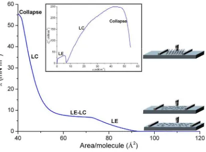
Figure 2.4. Model π -A isotherm with its corresponding representation of the inverse of the compressibility modulus (Cs−1) vs. the surface pressure (Inset). Both representations present the physical state at each zone of
the isotherm or the Cs−1curve. In addition, the scheme of the molecules orientation at each physical state is
presented.
METHODS FOR PREPARING SPB 17
In further compressing of the condensed phases, the molecules are forced out of the interfacial film and the monolayer collapses. The collapse situation can produce several effects on the interface film; being the formation of disordered multilayers over the interface film the most common. Other possible effects are the formation of micelles if the amphiphile posses a strong polar head group relatively to the non-polar part of the molecule. On the other hand, if the polarity of the headgroup of the molecule is not strong compared with the hydrophobic part, the molecules can form vesicles. This last situation applies mainly to long-chain molecules that possess two hydrocarbon chains for each polar headgroup.
The collapse region appearance is defined by the equilibrium spreading pressure which corresponds to the equilibrium pressure between the monolayer (2D state) and the solid (3D state). Over the equilibrium spreading pressure, the monolayer has the tendency to aggregate into crystals by nucleation and crystalline growth processes [8].
CHAPTER 2. FUNDAMENTAL TECHNIQUES
18
length of the isotherm is considerably reduced. Another factor to obtain more condensed phases is favouring complexes of metal ions with the acid headgroup of the fatty acids. The monolayer is always in a metastable state rather than in an absolutely stable equilibrium state, so the monolayer integrity can be lost. There are several factors that can enhance the monolayer integrity. The most important is the pH and the presence of multivalent ions in the aqueous subphase. In a general view, divalent metal ions interact with the acid headgroup of fatty acids depending on their electronegativity. At high electronegativity they interact covalently, whereas at low electronegativity they interact electrostatically being this behaviour a contribution for the alkyl chains packing [11].
Besides the temperature and the subphase conditions, the experimental part for recording a
π-A isotherm must be performed with a extreme cleanness and a precise control of several variables. These requirements are important due to the phase changes and especially the collapse region depend on the compression rate and the ageing time of the monolayer so a precise control of both variables is indispensable for a good reproducibility.
2.1.1.5 Langmuir π-A isotherms experimental information
The thermodynamic analysis of the Langmuir π-A isotherms offers a wide range of possibilities to study the film behaviour. Probably, the most used because of its high relevance for identification of states and phase transitions in the monolayers [12,13] is the inverse of the compressibility modulus. Others studies that can be performed investigate the ideality of a two-component mixture and the interaction forces between them. Finally, the phase rule can be applied to reveal the number of phases present at a given surface pressure.
Inverse of the compressibility modulus
The parameter used for phase identification is the inverse of the compressibility modulus, which is defined by Expression 2.9 where A is the mean area per molecule (Å2·molecule-1),
π the surface pressure (mN·m-1) and T is the absolute temperature.
T s dA d A C ⎟ ⎠ ⎞ ⎜ ⎝ ⎛ − =
METHODS FOR PREPARING SPB 19
As it has been stated by previous authors [13], an inverse of the compressibility modulus between 0 to 12.5 mN·m-1 indicates that this π-A isotherm zone corresponds to gas phase.
LE phase is accorded to be present between 12.5 to 50 mN·m-1, a LE-LC coexistance zone
between 50 to 100 mN·m-1 and LC between 100 to 250 mN·m-1. Above 250 mN·m-1 is
widely assumed to be in solid phase. In accordance to that, plotting the inverse of the compressibility modulus, the inflexion points (kink points) can be identified. The kink points can be caused by two film internal processes of the film: phase change or component separation in case of a mixed film.
The inset of Figure 2.4 presents the LE state at very low surface pressure and presents an inflexion point that indicates the beginning of the phase change from LE to LC. In the example case, although the curve achieves −1
s
C values close to 250 mN·m-1, solid phase is
not observed. Further compression of the LC state implies the collapse of the monolayer.
Mixture ideality and interactions between its components
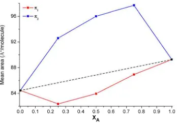
The representation of the mean area per molecule versus the molar fraction at a selected pressure gives valuable information about the ideality of the mixture at this surface pressure. The area per molecule of both pure components are connected, and it is set as the ideal mixture limit line, so that, any deviation from the ideal line indicates miscibility although non-ideality [14] (Figure 2.5). Negative deviations of the mean area per molecule of the mixtures (red line) referred to the ideal mixture line (dashed line) means that the balance between attractive and repulsive interactions between the monolayer components molecules is shifted to the monolayer components molecules attraction, at these composition and pressure conditions. Opposite behaviour is observed in the case of positive deviations (Blue line referred to dashed line), in which the attraction between molecules of the same component are larger than the interaction between molecules of different components [15,16].
The ideality of a mixture can also be studied through the free energy of mixing (ΔGmix). In
the case of a mixed monolayer of two components, ΔGmix can be expressed as [16-18]:
CHAPTER 2. FUNDAMENTAL TECHNIQUES
20
[image:30.595.108.456.166.416.2]ΔGid = RT(X1 ln X1 + X2 ln X2) Expression 2.11
Figure 2.5. Plot of the Mean area per molecule vs. the molar fraction representation for a mixture of components A and B. Dashed line represents the ideal behaviour for the selected surface pressure.
ΔGid is the ideal free energy of mixing, which can be evaluated from Expression 2.11,
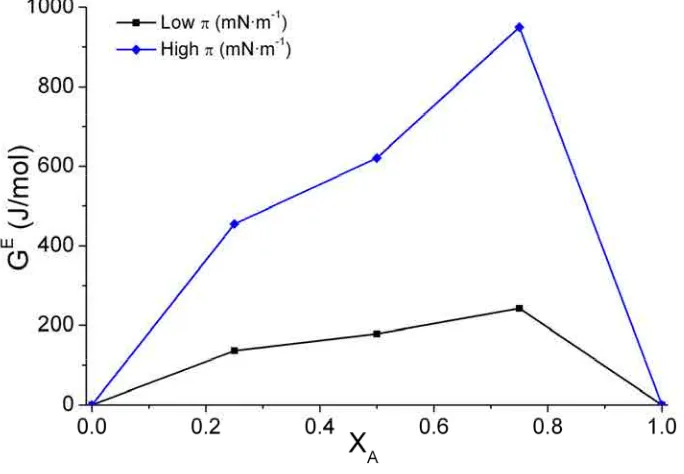
being R the gas constant and T the absolute temperature, and GE the excess free energy of mixing. GE is a representation of the free energy deviation of a real mixed system from an ideal mixed one. The GE at a specific surface pressure can be calculated from the π-A isotherm data through Expressions 2.12 and 2.13 for a system of two components, being NA
the Avogadro’s number and AE the excess area, A12 the mean area per molecule for the
mixture and, A1 and A2 the area per molecule for the individual components.
) ( 1 1 2 2 12 x A x A
A
AE = − + Expression 2.12
∫
= π π
0 A d
N
GE A E Expression 2.13
METHODS FOR PREPARING SPB 21
interactions between both components are not favoured compared with an ideal mixture suggesting that at least one component could form aggregates or enriched domains [16,19]. Therefore, negative GE values indicate attractive intermolecular interaction between
different components molecules. The presence of a minimum value at a given composition and surface pressure can be a sign of two different processes: First, at these conditions, the mixture presents the largest thermodynamic stability in comparison with the pure components. Second, it indicates the formation of a complex between molecules of different species.
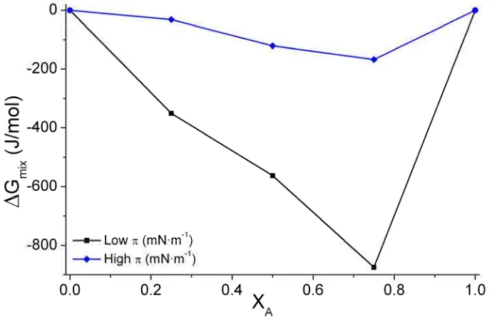
The representation of ΔGmix vs. one component molar fraction gives also information about
the mixing behaviour. ΔGmix negative values (Figure 2.7) indicate that the mixed
monolayers are more stable compared with non-mixed because of the entropic contribution. On the other hand, ΔGmix positive values indicate phase separation in the mixture. GE and
ΔGmix give different information, ΔGmix indicates whether the components are mixed or not
[image:31.595.144.486.431.668.2]and GE gives idea about the favouring interactions between components.
CHAPTER 2. FUNDAMENTAL TECHNIQUES
[image:32.595.111.456.111.337.2]22
Figure 2.7. Plot of the mixing energy vs. the molar fraction of components A and B.
Phase rule applied at Langmuir films
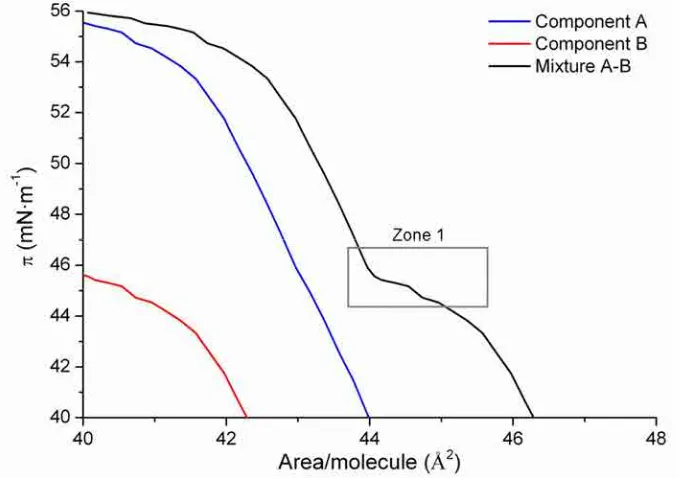
The thermodynamic study allows also to apply the phase rule to a selected zone of the π-A isotherm. It is commonly used in phase changes or just prior the collapse region. In the case of a two completely immiscible component mixture, it is frequent that one of the components collapse at lower surface pressures than the other. The presence of similar collapse pressures for the mixture and one of the components usually indicates that the component that collapses at a lower surface pressure has been expulsed and this fact can be confirmed with the phase rule.
Maintaining temperature and external pressure constant, the number of degrees of freedom F of the monolayer system is given by the Expression 2.14 [15]:
F = CB + CS− PB− PS + 1 Expression 2.14
Where CB is the number of components in the bulk, CS is the number of components
confined to the surface, PB is the number of bulk phases, and PS is the number of monolayer
phases in equilibrium with each other. In a π-A isotherm case, at the air|water interface, CB
= 2 (air and water), CS = 2 (Component A and B), and PB = 2 (gas and liquid), thus F=3−PS.
METHODS FOR PREPARING SPB 23
(condensed and collapsed state) so the system will have one degree of freedom. In the case of one of the pure components and the mixture have very similar collapse pressure (Figure 2.8), this indicates zero degrees of freedom, which is according with PS = 3. So that, at the
[image:33.595.143.485.240.479.2]collapse (Zone 1 in Figure 2.8) coexist component A condensed, component B condensed and collapse of component B. One clear example of this application is presented in Section 5.7.1.
CHAPTER 2. FUNDAMENTAL TECHNIQUES
24
2.1.1.6 Langmuir-Blodgett Technique
The Langmuir-Blodgett technique (LB) was introduced by Irving Langmuir and Katharine Blodgett in 1934 and it consists on transferring a part of the interfacial film (monolayer) like a carpet onto a solid plate (substrate) at a selected surface pressure. The relaxation time is the time waited since the target surface pressure is reached till the monolayer is stable after the compression. The stability of the monolayer can be checked observing no variations in the area or surface pressure during a period of time.
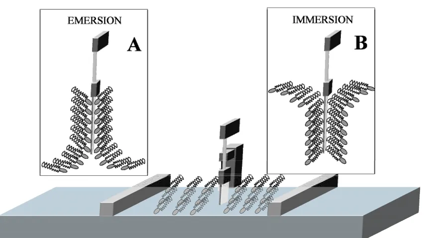
[image:34.595.74.500.461.700.2]The monolayer can be transferred as the substrate is lowered (immersion, or downstroke) or raised (emersion, or upstroke) through the interfacial film. Emersion (Figure 2.9A) is usually used for hydrophilic substrates and consist on that the substrate is immersed into the subphase before the amphiphile addition. The deposition of the first monolayer converts the substrate surface in hydrophobic, so the next monolayer will be deposited by an immersion process (Figure 2.9B). Conversely, a hydrophobic substrate becomes hydrophilic after the first monolayer deposition, so the second monolayer must be transferred by emersion. When building up multilayers the current hydrophilic character of the substrate surface after each monolayer deposition must be considered.
METHODS FOR PREPARING SPB 25
Pure Types of building up multilayers using the LB technique
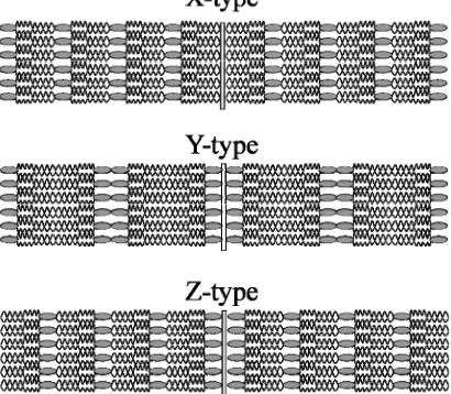
There are several types of building up multilayers (Figure 2.10), which depends on the amphiphilic balance of the molecules, the hydrophilic character of the substrate and the dipping conditions. These dipping conditions include the surface pressure, deposition speed, pH, temperature and composition of the subphase [7]. Sometimes a non-unique type is produced. The most used type (Y-type) consists on the deposition by immersion-emersion sequence or vice-versa. The Y-type is the most similar to the natural cell membranes. X-type deposition occurs when the monolayer have been only transferred by immersion and Z-type only by emersion. Z-type occurs commonly when performing multilayers of aromatic molecules with short or no hydrocarbon chains that do not form true monolayers at the air|water interface. A XY-type refers to the monolayer formed only by immersion but part of the monolayer is also transferred when raising the substrate out of the subphase.
[image:35.595.210.415.460.639.2]In a Y-Type LB film, the X-ray d spacing represents the distance between the polar planes, which means the thickness of two molecular layers. A X-ray d spacing less than twice the molecular length may indicate some tilting or interdigitation, or both.
Figure 2.10. Pure types of building up multilayers using LB technique.
CHAPTER 2. FUNDAMENTAL TECHNIQUES
26
angle formed in emersion by the water meniscus against the solid substrate is around 50˚–
60˚ [20]. The non-reactive deposition occurs in emersion process when the substrate surface
available area is higher than the molecular adsorption so part of the subphase remains at the air/substrate monolayer. In this case, the monolayer is poorly adhered and requires a waiting time for draining the subphase; otherwise this monolayer can be re-spread in the subphase when trying to build up one more layers.
In order to obtain reactive deposition, the transfer rate (speed at which the substrate is immersed or emerged) must be moderated according to the drainage speed, which depends on the crystallised state and the viscoelasticity properties of the monolayer [21]. Surface viscosity must be low enough to do not obtain a rigid and brittle film. Otherwise the meniscus between the substrate and the air|liquid interface is not good, resulting in a bad monolayer transfer.
In natural cell membranes it is often found that the upper lipid layer composition differs from the lower layer. The LB technique allows depositing films containing more than one type of monomolecular layer. This is possible by performing the LB using the compound A molecules by emersion and then, performing a LB using the compound B molecules by immersion. In this way, an alternate multilayer structure ABABAB is prepared. Asymmetric membranes by LB deposition are used for lipid phase-separation and lipid domain formation in mixed bilayers [7, 22, 23].
Asymmetric bilayers formed by zwitterionic phospholipids in the bottom layer and, in the top one, by anionic phospholipids favours the protein incorporation since many of them associate with membranes using interactions with anionic phospholipids. On the other hand, the asymmetric bilayer has lower defects density when the first layer is composed of phosphatidylethanolamine (PE) compared with phosphatidylcholine (PC) due to the different hydration shell [24, 25].
METHODS FOR PREPARING SPB 27
layer is attached to the substrate surface through stronger forces which could be a combination of electrostatic, hydrogen bond or chemical bond.
Transfer Ratio
Transfer ratio of a monolayer is the relation between the decrease of the monolayer area Sm
and the total substrate area (Ss) available for depositing the LB (Expression. 2.15). Sm is the
decrease of the interface monolayer area after the LB deposition maintaining constant the surface pressure. It must be highlighted that Ss includes all the sides of the substrate, the
face where we want to deposit the LB and the other substrate faces that are also immersed. Moreover it should be considered that sometimes the substrate faces are not all made of the same material, so having different hydrophilic behaviour and roughness, so that the monolayer affinity will be different for one face than the others. In this situation Sm will be
described by Expression 2.16 where f is the total number of substrate faces.
s m S S
TR = Expression 2.15
∑
= f sf
s S
S
1
Expression 2.16 A transfer ratio close to one is an indicator of a good deposition and that the molecules orientation on the substrate is very similar to their orientation on the water surface. An ideal Y-type film is a multilayer system with transfer ratio of one for both up and down directions [7]. There is a 20% acceptable tolerance for a good TR acceptance depending on the microscopic heterogeneities of the substrate surface or small molecular orientation changes during the deposition process. More than this tolerance, it is considered an unsatisfactory film deposition.
The obtaining of a good transfer ratio depends basically on the transfer surface pressure and the molecular interaction between the substrate and the layers. The transfer surface pressure implies a determined phase, lateral cohesion, homogeneity and alkyl chains tilting. However, some amphiphiles can change some of these parameters when changing the air|subphase interface to the air|solid interface.
CHAPTER 2. FUNDAMENTAL TECHNIQUES
28
emersion, and can also be different for the first monolayer than the subsequent. In the case of emersion, the transfer rate must be controlled according to the dynamic properties of the interface monolayer and the rate at which the subphase drains from the monolayer|solid interface [7]. This monolayer drainage depends on the adhesion of the monolayer onto the solid and the headgroup dehydration.
2.1.1.7 LB films special features
It is usual that LB films are prepared in condensed phases because the monolayer is close-packed with strong lateral cohesion and that permits a good deposition. The optimal pressure for LB formation is the pressure where the solid phase begins. This pressure combines a good lateral cohesion with low density of condensed domain defects. The decrease of surface tension when compressing the monolayer reduces the affinity of the polar group of the amphiphile for the water interface so increasing the importance of the polar group|substrate interactions and, in consequence, favouring the adsorption onto hydrophilic substrate. Despite the optimal pressure, LB of some amphiphiles has been also successfully transferred at the LE phase and also close to the collapse zone, where the monolayer is brittle [15].
METHODS FOR PREPARING SPB 29
The presence of subnanometer holes in phospholipid LB bilayers is explained by the lipids desorption of the first monolayer when transferring the second one [24]. The incoming phospholipids, thus cover only the hydrophobic surface of the first monolayer, maintain the substrate surface where the holes were. The presence of transbilayer holes are also due to desorption process, which is probably common in any supported bilayer system.
The monolayer is usually deposited preserving the surface variations of the underlying substrate, spanning the voids and other defects in the substrate. In the case of very irregular substrates, it is possible that the LB film can resemble the undulations of it. On the other hand, for surface roughness at the nanometric scale, at the moment of the deposition, the monolayer will bridge over the voids supported by a layer of water. When the water layer is drained or dried, the film will collapse [10].
Generally speaking, the adhesion of the first layer to the underlying substrate determines the quality of subsequent layers and this adhesion depends on the substrate surface, its chemical composition and the interaction forces between the substrate and the lipid. Several pre-treatments can be performed on the substrate to improve the first monolayer quality like lipid precoating, silanization, vacuum metal deposition, etc. This pre-treatment induces changes in the chemical and physical structure of the first monolayer but these changes does not apply to the next built up monolayers [6].
The highlights of this section are that a higher transfer surface pressure results in more uniform and tightly packed phospholipid bilayers with fewer pinhole defects [7], the first deposited monolayer highly determines the quality of the subsequent deposited monolayers. The most hydrophilic the substrate is, the better adsorption is achieved so more layers can be stacked.
CHAPTER 2. FUNDAMENTAL TECHNIQUES
30
2.1.2 SPB technique by vesicle fusion
2.1.2.1 Vesicles preparation
The exposition of given amphiphilic lipids with high hydrophobic tails to an aqueous environment form closed spherical structures called vesicles or liposomes. They are the most energetically stable form in water hiding the hydrophobic tail from the water contact forming a hydrophobic region and exposing their hydrophilic head to the aqueous solution, so obtaining a hydrophilic environment at both sides of the vesicle and a hydrophobic part between layers. The first study with vesicles was performed by Bangham [27] who concluded that ions cross these vesicles in a similar manner that it is observed in biological membranes. Therefore, it was the beginning of using vesicles as biomimetic membranes. One of the most important features of vesicles is lamellarity, which indicates the number of bilayers contained within a single vesicle. It can be distinguished two different lamellar organizations. A unilamellar vesicle (sphere of one bilayer) is the less stable, but is the most used in biomimetic membranes. The second organization is multilamellar vesicles (MLVs) ranging from 0.1 to 10 μm in diameter. Unilamellar can also be divided into three groups, small unilamellar vesicles (SUVs) with less than 100 nm of diameter, large unilamellar vesicles (LUVs) with a diameter ranging between 100 to 500 nm and Giant unilamellar vesicles (GUV) with a diameter larger than 1μm.
The structural properties of the vesicles depend on several factors being the most influents the composition and concentration of the constituent lipids. Moreover, the time of hydration and the ionic strength of the medium affect the liposomal size and fluidity.
METHODS FOR PREPARING SPB 31
is gently agitated for rehydration. It is relevant to consider that long time is required when performing the rehydration step for encapsulating external molecules in lipid vesicles. The vesicles formation includes the organic solvent evaporation and electrolyte addition. These steps swell the bilayer thanks to the increased water content. Then, the bilayer formed in the flask walls is fragmented into small patches, which have the hydrophobic chains of the edges exposed to water. Beyond a critical radius these patches close and form vesicles.
Post-treatments can be applied to obtain the desired vesicle size. The most used methods are sonication during the rehydration step, so obtaining SUVs, and vesicle extrusion through polycarbonate filters of known pore size after the rehydration step. Other procedures can be used like freeze – thawing, ethanol injection and detergent adding method, but all of them have, in general, more disadvantages than the sonication or extrusion method, and they are basically used for a specific objective.
2.1.2.2 Vesicle fusion method for SPB formation
The vesicle fusion method for SPB preparation is the most used method for bilayer formation, and it consists on placing a drop of the reconstituted vesicle solution on the substrate surface and then, incubates it at temperature above the phase transition temperature (Tm) from the gel phase to liquid crystalline phase (Lα) of the lipid, in order to
maintain the lipid membrane fluidity. The process implies the interaction vesicle-substrate (adsorption), the vesicles aperture (rupture) forming SPB patches and finally the spreading and fusion of these patches to form microscopically large zones of SPB. The SPB formation traps a water layer of 10-20 Å that separates the substrate and the SPB and permits it to maintain its fluidity.
CHAPTER 2. FUNDAMENTAL TECHNIQUES
32
[image:42.595.63.503.243.591.2]The vesicle fusion mechanism is presented in Figure 2.11. Vesicles arrive to the working substrate surface, adsorb, flatten and open forming a high density phase patch. The destabilization of this high density phase and the amphiphilic nature of lipids lead the lipid propagation over the surface forming a low-density phase [28]. Bilayers usually have zero spontaneous curvature, so Gibbs energy is requested for bending them, in consequence, the SPB propagation on a nanometric rough substrate surface implies the bending of the bilayer around contoured regions without increasing the membrane’s distance from the surface [29].
Figure 2.11. SPB formation scheme.
The flattening is not always observed. The driving force for this step depends on the nature of the substrate surface. In fact, the rate of the vesicle adsorption and flattening step is a good indicator of the lipid-substrate affinity [30].
METHODS FOR PREPARING SPB 33
of certain molecules to the lipid vesicles maintains the mechanism but may slow down one of the steps favouring the vesicle deposition. The balance between the hydrophobic energy of the disk edge and the bending energy leads the vesicles aperture or the remaining in flat disk shape. The height of these disks is double to that of the SPB so it can be easily recognized in AFM images. Vesicles may aggregate and return to the equilibrium lamellar phase in excess of solvent. It has been observed that the minimum radius for bilayer retransforming in vesicles is 3-5 times the bilayer thickness [33].
Seifert and Lipowsky [34] proposed that the bilayer is comparable with a 2D sheet embedded in a 3D space and the adsorption, rupture and spreading depends on the balance between the gain in adhesion energy and the vesicles curvature energy. However, recent studies propose that more factors are involved in the SPB formation like the distribution of different lipids in a multispecie vesicle and the interaction between vesicles. This interaction is called critical vesicular coverage (CVC) and it refers to the minimum adsorbed vesicles quantity required for vesicle aperture thanks to the interaction between neighbouring vesicles [35].
The aperture of vesicles implies that the patches expose an edge to the solution. These edges, are thermodynamically unstable so the spreading and fusion with other patches is favoured to decrease the edge length exposed to the solution [36,37]. After the SPB is formed, it must be always kept wet and warm to maintain its characteristics. However, some researchers have developed several techniques to prepare air-stable lipid SPB [38] but they have some disadvantages, especially in fluidity.
External influences to the SPB formation
CHAPTER 2. FUNDAMENTAL TECHNIQUES
34
The vesicle size is an important factor due to it influences the kinetics of vesicle aperture and fusion, being slower the vesicle fusion rate as smaller the vesicle are. This is the rate-limiting step due to small vesicles are stable in vesicle form on the substrate [43], according to the Raviakine and Brisson observations [41] that vesicle fuse when their radius is larger than the critical radius. Once opened, curved membrane areas are more hydrophobic and they have a higher surface energy than the less curved zones, so curved areas are more prone to membrane fusion [44]. In the case of large or giant vesicles, each lipid molecule experiences a flat curvature similar to that observed in the planar lamellar phase [33], so the deposition is favoured.
Temperature is an important influence in vesicle fusion due to the vesicle aperture is enhanced when increasing the temperature of the system, especially when working above the melting temperature (Tm) [39,45]. On the other hand, after the SPB has been formed, a
reduction of the temperature has non-desired effects like shrink and cracking depending on the lipid phase [46-48].
At low pH and high ionic strength, negatively charged vesicles adsorb and fuse rapidly on nanometric roughness glass due to the favourable van der Waals forces [29]. Increasing the pH or reducing the ionic strength, provokes electrostatic repulsions between the surface and the vesicles, which may overwhelms the van der Waals attraction. Once the SPB has been adhered, it is difficult to reverse the process using variations of pH or ionic strength [29]. On the other hand, the creeping rate of the SPB on the substrate surface, which in natural mimicking conditions is ≈ 15 μm·min-1 [29], or the holes healing rate can be tunned modifying the pH and ionic strength conditions. On the other hand, the adsorption process can be enhanced adding divalent cations (Ca2+, Mg2+) or adding fusigenic agents (i.e.
polyethylene glycol) but its effects on the system must be previously considered.
METHODS FOR PREPARING SPB 35
Partial bilayer asymmetry can be obtained adding Ca2+ [47,49] or using chemical methods like pH changes or osmotic pressure alterations, which acts preferently on the outer layer [50]. On the other hand, the modification of the substrate charge can also favour the spreading [51].
2.1.3 Differences between the biomimetic membranes formed using each method
[image:45.595.256.369.335.496.2]The method used for biomimetic membrane deposition influences several features of the resulting membrane. Probably, the most relevant is the thickness since to the bilayer formed using the LB-LS method is thicker than the same bilayer formed using vesicle fusion method [52,53], which is explained by the differences in the tilt angle (Figure 2.12).
Figure 2.12. Scheme of the lipid tilt angle (α)
The Expression 2.17 relates the tilt angle (α) and the thickness (d) of a bilayer, considering that the bilayer thickness is ≈ 5.4 nm when the tilt angle is 0º.
4 . 5
CHAPTER 2. FUNDAMENTAL TECHNIQUES
36
The tilt angle of each leaflet of a SPB can be obtained separately using isotopically labelled phospholipids, and the results for DMPC indicate that in the adsorbed state on gold, the top layer is ≈ 35º whereas the bottom layer is ≈ 25º indicating that the different environment of each leaflet (aqueous solution vs. substrate surface) leads to a different tilting angle [56]. The top leaflet has a tilting angle similar to that of the monolayer at the air|solution interface thanks to the low interaction with lower leaflet, whereas the lower leaflet has a different tilting angle due to the stronger interactions with the substrate [117]. Therefore, the application of potential in the adsorbed state induces more tilting change in the top leaflet [55]. In the detached state, after potential application, the lipid sawtooth fashion induces changes in the compactness of the upper layer, so reducing the tilt angle [118]. It is worth to explain the differences between the techniques used to measure the thickness. The diffraction method involves an interpretation of the electron density or electron scattering length density profiles, whereas AFM may involve an error due to the substrate roughness or the absence of layer defects. The use of force curves involves an error caused by the tip-sample interactions that leads to smaller thicknesses compared with other techniques [54].
SPB formed by vesicle fusion should have a similar shape capacitance curve than the LB-LS if the vesicles have been correctly opened and fused. Otherwise, the dissimilar shape of the capacitance curves indicates that vesicles may be adhered but not fused on the substrate surface [43].
METHODS FOR PREPARING SPB 37
whose breakthrough force is two hundred-fold the monolayer value [57]. The interactions between water molecules are ten times stronger than the water-alkyl chains, so reducing the stability of the monolayer [58]. In the case of phospholipid bilayers, the van der Waals interactions between the alkyl chains of both leaflets stabilize the bottom leaflet obtaining a higher temperature of phase transition [57].
The monolayer formed using LB can be stabilized thanks to the elimination of the aqueous medium, so obtaining the LB monolayer in air. Air is more hydrophobic than the aqueous solution so the alkyl chains of the LB in air suffers less repulsion, and in consequence, the melting temperature is increased. However, the air-stabilization in LB is lower than the alkyl-stabilization between both leaflets in a SPB [57].
2.1.4 Limitations of biomimetic membranes
CHAPTER 2. FUNDAMENTAL TECHNIQUES
38
[image:48.595.68.498.399.598.2]One particular case of biomimetic membrane is referred to the lipid layers formed underwater which can bridge small holes. A bilayer formed in that way is called black lipid membrane (BLM) and it is used for ion transport studies. A BLM is a bilayer formed on a small aperture with a diameter less than 1 mm. The hole is formed on a hydrophobic material wall which separates two compartments that can be filled with different aqueous solutions. Then, BLM are suspended in solution so there are no interferences with the support as happens with SPB and also permits the presence of transmembrane proteins without denaturalizing it. This BLM is more mobile and active than SPB, but its stability and robustness is very low, and it can not be widely characterized. The main application of BLM is the study of ion channels in phospholipids bilayers, so it will not be used in this Ph.D. Thesis.
MOLECULES AND SUBSTRATES IN SPB 39
2.2 Molecules and substrates used for biomimetic membranes
preparation
2.2.1 Amphiphilic molecules in biomimetic membranes
The membrane amphiphilic molecules major present in natural cells have a highly hydrophilic part due to the polar headgroup in glycolipids, or the zwitterionic or anionic headgroup in other lipid families. In most of the cases, the presence in the molecule of two hydrocarbon chains confers a high hydrophobic character to the tail, which balances the strongly hydrophilic character of the headgroup [7].
There is a large range of amphiphilic molecules that are able to form biomimetic membranes being fatty acids, phospholipids and glycolipids the most important for preparing biomimetic membrane. Cholesterol, a type of steroid, is also important because its large presence in cell membranes [7].
The amphiphile affinity for the air|water interface is consequence of the physico-chemical properties of the hydrophilic part (polarity, size, charge and hydration capacity) and the hydrophobic part (alkyl chain length). When the balance between the hydrophobic and the hydrophilic forces is disrupted, the amphiphile could not form a stable monolayer. In the case of the dominant hydrophilic part, like amphiphiles with only an alkyl chain, this chain should be at least of 12 hydrocarbons long. Otherwise, this compound will be partially solved in the subphase and the molecules remaining in the interface will form micelles. On the other hand, if the hydrophobic part is dominant, the amphiphile may crystallize on the subphase surface.
2.2.2 Substrate relevance for preparing biomimetic membranes
CHAPTER 2. FUNDAMENTAL TECHNIQUES
40
when the water layer present close to the lipid heads and the water layer on the substrate surface overlap, hindering the adsorption from a thermodynamic or a kinetic point of view. Mica, which is the main model for substrates, has a water contact angle less than 10º [61]. The contact angle for ITO is ≈ 35º [62] whereas for smooth gold is 70º [63] and for the most hydrophobic metal (Hg) is above 100º [64]. The Electro-wetting on dielectric (EWOD) method permits changing the wettability of a dielectric surface by applying voltage across the dielectric layer. This feature permits changing the contact angle of the droplet on the selected surface [65].
Nevertheless, hydrophilicity is a general requirement but not always sufficient for a correct spreading, so the experimental conditions and pre-treatments can help to extend large zones of SPB of a certain lipid in unfavoured conditions. This is the case of low hydrophilic substrates that can be used when enhancing its hydrophilicity or preparing SAMs (See Section 2.14) prior the SPB deposition.
In addition to the correct bilayer spreading, SPB substrates must show other features depending on the applications, for instance, when a conductive substrate is requested. In this line, several attempts of SPBs have been performed on gold, silver, platinum and indium tin oxide (ITO) [59]. Although an atomically surface roughness is the best option, high quality SPB have been prepared in nanometric roughness [72] and the result is that the bilayer resembles the substrate surface topography.
MOLECULES AND SUBSTRATES IN SPB 41
The presence of the lipid layer in a hydrophobic substrate may facilitate the redox activity of a molecule compared with the same substrate without the lipid layer. Some procedures permits to convert a hydrophobic substrate in a hydrophilic one, although the resulting substrates may not behave ideally [68]. In hydrophilic substrates, the presence of SPB slow down the electron transfer achieving, in some cases, two orders of magnitude [69]. On the other hand, the protons requested for the reduction of trapped redox couple are provided from the solution side [51,70], although in some buffer cases, water molecules act as electron donor. The addition of an electron donor (like EDTA) to the solution enhances the electron transfer towards the electrode. Viceversa occurs with an electron acceptor (like Fe(CN)63-) [69].
Other substrate properties like surface chemistry, charge and morphology affect the deposited bilayer properties such as fluidity, permeability and thermotropic behaviour. Moreover, they can favour the formation of domains and asymmetric molecular distribution across leaflets in mixed lipid bilayers [71]. The substrates selected for forming a high quality SPB with little defect density and high lipid mobility should be hydrophilic, smooth and clean. The most common case is the extension of vesicles with positively charged head lipids spread on negative hydrophilic surfaces like mica.
2.2.2.1 Substrates used in this Ph. D. Thesis
Mica
Muscovite mica is composed by several negatively charged layers that are maintained together by K+ interlayer cations. Each stratum has two hexagonal layers of SiO4
crosslinked by the Aluminium atoms with incorporated OH- groups [30]. The cleavage of mica breaks the electrostatic bond between the K+ and the oxygen atoms. In aqueous neutral buffered solution mica has a negative charge due to the mismatch between the sublayer of OH- (complexed to Al3+) and the surface bound K+ ions. This phenomenon