Author
Department of Food Science and Technology Agricultural University of Athens
Athens, Greece
ISBN: 978-0-387-73513-9 eISBN: 978-0-387-73514-6 Library of Congress Control Number: 2007939831
#2008 Springer Science+Business Media, LLC
All rights reserved. This work may not be translated or copied in whole or in part without the written permission of the publisher (Springer Science+Business Media, LLC., 233 Spring Street, New York, NY10013, USA), except for brief excerpts in connection with reviews or scholarly analysis. Use in connection with any form of information storage and retrieval, electronic adaptation, computer software, or by similar or dissimilar methodology now known or hereafter developed is forbidden.
The use in this publication of trade names, trademarks, service marks, and similar terms, even if they are not identified as such, is not to be taken as an expression of opinion as to whether or not they are subject to proprietary rights.
Preface . . . vii
1. Conversion of Units . . . 1 Examples
Exercises
2. Use of Steam Tables. . . 5 Review Questions
Examples Exercises
3. Mass Balance. . . 11 Review Questions
Examples Exercises
4. Energy Balance . . . 21 Theory
Review Questions Examples
Exercises
5. Fluid Flow . . . 33 Review Questions
Examples Exercises
6. Pumps. . . 41 Theory
Review Questions Examples
Exercises
7. Heat Transfer By Conduction. . . 55 Theory
Review Questions Examples
Exercises
8. Heat Transfer By Convection. . . 67 Theory
Review Questions Examples
Exercises
9. Heat Transfer By Radiation. . . 95 Review Questions
Examples Exercises
10. Unsteady State Heat Transfer . . . 101 Theory
Review Questions Examples
Exercises
11. Mass Transfer By Diffusion. . . 141 Theory
Review Questions Examples
Exercises
12. Mass Transfer By Convection . . . 155 Theory
Review Questions Examples
Exercises
13. Unsteady State Mass Transfer. . . 163 Theory
Review Questions Examples
Exercises
14. Pasteurization and Sterilization . . . 181 Review Questions
15. Cooling and Freezing . . . 193
Review Questions Examples Exercises 16. Evaporation . . . 215
Review Questions Examples Exercises 17. Psychrometrics. . . 237
Review Questions Examples Exercises 18. Drying . . . 253
Review Questions Examples Exercises References . . . 273
Appendix: Answers to Review Questions . . . 275
Moody diagram . . . 280
Gurney-Lurie charts . . . 281
Heisler charts . . . 284
Pressure-Enthalpy chart for HFC 134a . . . 285
Pressure-Enthalpy chart for HFC 404a . . . 286
Psychrometric chart . . . 287
Bessel functions . . . 288
Roots ofdtand=Bi . . . 290
Roots ofdJ1(d)-Bi Jo(d)=0 . . . 291
Roots ofdcotd=1-Bi . . . 292
Error function . . . 293
Food engineering is usually a difficult discipline for food science students because they are more used to qualitative rather than to quantitative descrip-tions of food processing operadescrip-tions. Food engineering requires understanding of the basic principles of fluid flow, heat transfer, and mass transfer phenomena and application of these principles to unit operations which are frequently used in food processing, e.g., evaporation, drying, thermal processing, cooling and freezing, etc. The most difficult part of a course in food engineering is often considered the solution of problems. This book is intended to be a step-by-step workbook that will help the students to practice solving food engineering problems. It presumes that the students have already studied the theory of each subject from their textbook.
The book deals with problems in fluid flow, heat transfer, mass transfer, and the most common unit operations that find applications in food processing, i.e., thermal processing, cooling and freezing, evaporation, psychometrics, and drying. The book includes 1) theoretical questions in the form ‘‘true’’ or ‘‘false’’ which will help the students quickly review the subject that follows (the answers to these questions are given in the Appendix); 2) solved problems; 3) solved problems; and 4) problems solved using a computer. With the semi-solved problems the students are guided through the solution. The main steps are given, but the students will have to fill in the blank points. With this technique, food science students can practice on and solve relatively difficult food engineering problems. Some of the problems are elementary, but problems of increasing difficulty follow, so that the book will be useful to food science students and even to food engineering students.
A CD is supplied with the book which contains solutions of problems that require the use of a computer, e.g., transient heat and mass transfer problems, simulation of a multiple effect evaporator, freezing of a 2-D solid, drying, and others. The objectives for including solved computer problems are 1) to give the students the opportunity to run such programs and see the effect of operating and design variables on the process; and 2) to encourage the students to use computers to solve food engineering problems. Since all the programs in this CD are open code programs, the students can see all the equations and the logic behind the calculations. They are encouraged to see how the programs work
and try to write their own programs for similar problems. Since food science students feel more comfortable with spreadsheet programs than with program-ming languages, which engineering students are more familiar with, all the problems that need a computer have EXCEL1spreadsheet solutions.
I introduce the idea of a digital SWITCH to start and stop the programs when the problem is solved by iteration. With the digital SWITCH, we can stop and restart each program at will. When the SWITCH is turned off the program is not running, so that we can change the values of the input variables. Every time we restart the program by turning the SWITCH on, all calculations start from the beginning. Thus it is easy to change the initial values of the input variables and study the effect of processing and design parameters. In the effort to make things as simple as possible, some of the spreadsheet programs may not operate on some sets of parameters. In such cases, it may be necessary to restart the program with a different set of parameters.
I am grateful to Dr H. Schwartzberg, who read the manuscripts and made helpful suggestions. I will also be grateful to readers who may have useful suggestions, or who point out errors or omissions which obviously have slipped from my attention at this point.
Athens Stavros Yanniotis
Show me and I will understand
Involve me and I will learn’’
Conversion of Units
Table 1.1 Basic units
Time Length Mass Force Temperature
SI s m kg – K,0C
CGS s cm g – K,0C
[image:11.439.88.352.308.443.2]US Engineering s ft lbm lbf 0R,0F
Table 1.2 Derived units
SI US Engineering
Force N (1 N = 1 kg m/s2) –
Energy J (1 J = 1 kg m2/s2) Btu
Power W (1 W = 1 J/s) HP, PS
Area m2 ft2
Volume m3(1m3= 1000 l) ft3
Density kg/m3 lb
m/ft3
Velocity m/s ft/s
Pressure Pa (1 Pa = 1 N/m2)
bar (1 bar = 105Pa)
torr (1 torr = 1 mmHg) atm (1 atm = 101325 Pa)
psi=lbf/in2
Table 1.3 Conversion factors
1 ft = 12 in = 0.3048 m 0F = 32þ1.8*0C
1 in = 2.54 cm 0C = (0F-32)/1.8
1 US gallon = 3.7854 l 0R = 460þ0F
1 lbm= 0.4536 kg K = 273.15þ0C
1 lbf= 4.4482 N
1 psi = 6894.76 Pa 0C =0F/1.8
1 HP =745.7 W 0C =K
1 Btu = 1055.06 J = 0.25216 kcal 0F =0R 1kWh = 3600 kJ
S. Yanniotis,Solving Problems in Food Engineering. ÓSpringer 2008
[image:11.439.92.350.488.592.2]Examples
Example 1.1
Convert 100 Btu/h ft2oF to kW/m2oC Solution
100 Btu
h ft28F¼100 Btu h ft28F
1055:06 J
1 Btu 1 kJ 1000 J 1 h 3600s 1ft2 0:3048 m
ð Þ2
1:8
8F
18C 1 kW
1 kJ=s¼0:5678 kW m28C
Example 1.2
Convert 100 lb mol/h ft2to kg mol/s m2 Solution
100lb mol h ft2 ¼100
lbmol h ft2
0:4536 kg mol
lb mol
1 h 3600 s
1 ft2 0:3048 m
ð Þ2¼0:1356
kg mol s m2
Example 1.3
Convert 0.5 lbfs/ft2to Pas
Solution
0:5lbfs ft2 ¼0:5
lbfs
ft2
4:4482 N lbf
1 ft
2
0:3048 m
ð Þ2
1 Pa 1 N=m2
ð Þ¼23:94 Pa s
Exercises
Exercise 1.1
Make the following conversions: 1) 10 ft lbf/lbmto J/kg, 2) 0.5 Btu/lbm
o
Solution
1) 10ft lbf lbm
¼10ft lbf lbm
::::::::::::::m
ft
:::::::::::::::N 1 lbf
::::::::::::::lbm
0:4536 kg
:::::::::::::J m N
¼29:89J kg
2) 0:5 Btu lbm8F
¼0:5 Btu lbm8F
1055:06 J
::::::::::
::::::::::::: :::::::::::::
1:88F
18C ¼2094:4 J kg8C
3) 32:174lbmft lbfs2
¼32:174lbmft lbfs2
:::::::::::::::
:::::::::::::::lbm
::::::::::::::::::m
1 ft
::::::::::::::: 4:4482 N
¼1 kg m N s2
4) 1000lbmft s2 ¼1000
lbmft
s2
0:4536 kg ::::::::::::::::
::::::::::::::::
1 ft
1 N
1 kg m=s2¼138:3 N
5) 10 kcal
min ftoF¼10
kcal min ftoF
1055:06 J 0:252 kcal
:::::::::min
60s
::::::::::::ft :::::::::::m
:::::::::::8F ::::::::::K
:::::::::W
::::::::::J=s¼4121 W m K
6) 30 psia¼30lbf in2
::::::::::::::::in2
:::::::::::::::::m2
::::::::::::::::::N ::::::::::::::::::lbf
:::::::::::::::::Pa
::::::::::::::N=m2
:::::::::::::::::atm
:::::::::::::::::Pa ¼2:04 atm 7) 0:002kg
m s¼0:002 kg m s
::::::::::::::lbm
:::::::::::::::kg
:::::::::::::::m
::::::::::::::::::ft¼0:0013 lbm
ft s
8) 5 lb mol h ft2mol frac¼5
lb mol h ft2mol frac
::::::::::::::::kg mol :::::::::::::::lb mol
:::::::::::::::::h ::::::::::::::::::s
:::::::::::::::::ft
2
:::::::::::::::::::m2¼6:7810
3 kg mol
sm2mol frac
9) 1:987 Btu
lb mol8R¼1:987 Btu lb mol8R
::::::::::::::cal ::::::::::::::Btu
::::::::::::::::lb mol ::::::::::::::::g mol ¼
::::::::::::::8R
::::::::::::K ¼1:987 cal g mol K
10) 10:731 ft
3 lb f
in2lb mol8R¼10:731
ft3 lb f
in2lb mol8R
::::::::::::::::m3
:::::::::::::::::::ft3
::::::::::::::::N ::::::::::::::::::lbf
::::::::::::::::in
2
:::::::::::::::::::m2
:::::::::::::lb mol :::::::::::::kg mol
1:88R K
Exercise 1.2
Make the following conversions:
251oF tooC (Ans. 121.7oC) 500oR to K (Ans. 277.6 K) 0.04 lbm/in3to kg/m3
(Ans. 1107.2 kg/m3)
12000 Btu/h to W (Ans. 3516.9 W ) 32.174 ft/s2to m/s2
(Ans. 9.807 m/s2)
0.01 ft2/h to m2/s (Ans. 2.58x10⁻⁷m2/s) 0.8 cal/goC to J/kgK (Ans. 3347.3 J/kgK) 20000 kg m/s2m2to psi
(Ans. 2.9 psi)
0.3 Btu/lbmoF to J/kgK
(Ans. 1256 J/kgK) 1000 ft3/(h ft2psi/ft) to
cm3/(s cm2Pa/cm)
Use of Steam Tables
Review Questions
Which of the following statements are true and which are false? 1. The heat content of liquid water is sensible heat.
2. The enthalpy change accompanying the phase change of liquid water at constant temperature is the latent heat.
3. Saturated steam is at equilibrium with liquid water at the same temperature. 4. Absolute values of enthalpy are known from thermodynamic tables, but for
convenience the enthalpy values in steam tables are relative values. 5. The enthalpy of liquid water at 273.16 K in equilibrium with its vapor has
been arbitrarily defined as a datum for the calculation of enthalpy values in the steam tables.
6. The latent heat of vaporization of water is higher than the enthalpy of saturated steam.
7. The enthalpy of saturated steam includes the sensible heat of liquid water. 8. The enthalpy of superheated steam includes the sensible heat of vapor. 9. Condensation of superheated steam is possible only after the steam has lost
its sensible heat.
10. The latent heat of vaporization of water increases with temperature. 11. The boiling point of water at certain pressure can be determined from steam
tables.
12. Specific volume of saturated steam increases with pressure. 13. The enthalpy of liquid water is greatly affected by pressure.
14. The latent heat of vaporization at a certain pressure is equal to the latent heat of condensation at the same pressure.
15. When steam is condensing, it gives off its latent heat of vaporization. 16. The main reason steam is used as a heating medium is its high latent heat value. 17. About 5.4 times more energy is needed to evaporate 1 kg of water at 1008C
than to heat 1 kg of water from 08C to 1008C.
18. The latent heat of vaporization becomes zero at the critical point.
19. Superheated steam is preferred to saturated steam as a heating medium in the food industry.
S. Yanniotis,Solving Problems in Food Engineering. ÓSpringer 2008
20. Steam in the food industry is usually produced in ‘‘water in tube’’ boilers. 21. Water boils at 08C when the absolute pressure is 611.3 Pa
22. Water boils at 1008C when the absolute pressure is 101325 Pa.
23. Steam quality expresses the fraction or percentage of vapor phase to liquid phase of a vapor-liquid mixture.
24. A Steam quality of 70% means that 70% of the vapor-liquid mixture is in the liquid phase (liquid droplets) and 30% in the vapor phase.
25. The quality of superheated steam is always 100%.
Examples
Example 2.1
From the steam tables:
Find the enthalpy of liquid water at 508C, 1008C, and 1208C. Find the enthalpy of saturated steam at 508C, 1008C, and 1208C. Find the latent heat of vaporization at 508C, 1008C, and 1208C.
Solution
Step 1
From the column of the steam tables that gives the enthalpy of liquid water read:
Hat508C¼209:33kJ=kg Hat1008C¼419:04kJ=kg Hat1208C¼503:71kJ=kg Step 2
From the column of the steam tables that gives the enthalpy of saturated steam read:
Hat508C¼2592:1kJ=kg Hat1008C¼2676:1kJ=kg Hat1208C¼2706:3kJ=kg Step 3
Calculate the latent heat of vaporization as the difference between the enthalpy of saturated steam and the enthapy of liquid water.
Example 2.2
Find the enthalpy of superheated steam with pressure 150 kPa and temperature 1508C.
Solution
Step 1
Find the enthalpy from the steam tables for superheated steam:
Hsteam¼2772:6kJ=kg
Step 2
Alternatively find an approximate value from:
Hsteam ¼Hsaturatedþcp vaporðTTsaturationÞ ¼2693:4þ1:909ð150111:3Þ
¼2767:3kJ=kg
Example 2.3
If the enthalpy of saturated steam at 508C and 558C is 2592.1 kJ/kg and 2600.9 kJ/kg respectively, find the enthalpy at 538C.
Solution
Find the enthalpy at 538C by interpolation between the values for 508C and 558C given in steam tables, assuming that the enthalpy in this range changes linearly:
H¼2592:1þ5350
5550ð2600:92592:1Þ ¼2597:4 kJ=kg
Exercises
Exercise 2.1
Find the boiling temperature of a juice that is boiling at an absolute pressure of 31.19 Pa. Assume that the boiling point elevation is negligible.
Solution
Exercise 2.2
A food product is heated by saturated steam at 1008C. If the condensate exits at 908C, how much heat is given off per kg steam?
Solution
Step 1
Find the the enthalpy of steam and condensate from steam tables:
Hsteam¼::::::::::::::::::::::::::::::::::kJ=kg;
Hcondensate¼::::::::::::::::::::::::::::::::::kJ=kg:
Step 2
Calculate the heat given off:
H¼::::::::::::::::::::::::::::::::::::::::::::::::::::¼2299:2 kJ=kg
Exercise 2.3
Find the enthalpy of steam at 169.06 kPa pressure if its quality is 90%. Solution
Step 1
Find the enthalpy of saturated steam at 169.06 kPa from the steam tables:
Hsteam¼:::::::::::::::::::::::::::::::::::::::::::::::::::
Step 2
Find the enthalpy of liquid water at the corresponding temperature from the steam tables:
Hliquid¼::::::::::::::::::::::::::::::::::::::::::::::::::::::::
Step 3
Calculate the enthalpy of the given steam: H¼xsHsþð1xsÞHL¼
¼::::::::::::::::::::::::::::::::::::::þ:::::::::::::::::::::::::::::::::::¼ 2477:3kJ=kg
Exercise 2.4
Find the vapor pressure of water at 728C if the vapor pressure at 708C and 758C is 31.19 kPa and 38.58 kPa respectively.
Exercise 2.5
The pressure in an autoclave is 232 kPa, while the temperature in the vapor phase is 1208C. What do you conclude from these values?
Solution
The saturation temperature at the pressure of the autoclave should be ... Since the actual temperature in the autoclave is lower than the saturation temperature at 232 kPa, the partial pressure of water vapor in the autoclave is less than 232 kPa. Therefore air is present in the autoclave.
Exercise 2.6
Lettuce is being cooled by evaporative cooling in a vacuum cooler. If the absolute pressure in the vacuum cooler is 934.9 Pa, determine the final tem-perature of the lettuce.
Mass Balance
Review Questions
Which of the following statements are true and which are false? 1. The mass balance is based on the law of conservation of mass.
2. Mass balance may refer to total mass balance or component mass balance. 3. Control volume is a region in space surrounded by a control surface
through which the fluid flows.
4. Only streams that cross the control surface take part in the mass balance. 5. At steady state, mass is accumulated in the control volume.
6. In a component mass balance, the component generation term has the same sign as the output streams.
7. It is helpful to write a mass balance on a component that goes through the process without any change.
8. Generation or depletion terms are included in a component mass balance if the component undergoes chemical reaction.
9. The degrees of freedom of a system is equal to the difference between the number of unknown variables and the number of independent equations. 10. In a properly specified problem of mass balance, the degrees of freedom
must not be equal to zero.
Examples
Example 3.1
How much dry sugar must be added in 100 kg of aqueous sugar solution in order to increase its concentration from 20% to 50%?
S. Yanniotis,Solving Problems in Food Engineering. ÓSpringer 2008
Solution
Step 1
Draw the process diagram:
S1
S2
S3 20%
100%
50% MIXING
100 kg
Step 2
State your assumptions:
l dry sugar is composed of 100% sugar.
Step 3
Write the total and component mass balances in the envelope around the process:
i) Overall mass balance
100þS2¼S3 (3:1)
ii) Soluble solids mass balance
0:20100þS2¼0:50S3 (3:2)
Solving eqns (3.1) and (3.2) simultaneously, find S2=60 kg and S3=160 kg. Therefore 60 kg of dry sugar per 100 kg of feed must be added to increase its concentration from 20% to 50%.
Example 3.2
Solution
Step 1
Draw the process diagram:
10000 kg/h X Y
F 60%
12%
42% 12%
W
MIXING EVAPORATION
II I
Step 2
Write the total and component mass balances in envelopes I and II: i) Overall mass balance in envelope I
10000¼WþX (3:3)
ii) Soluble solids mass balance in envelope I
0:1210000¼0:60X (3:4)
iii) Overall mass balance in envelope II
XþF¼Y (3:5)
iv) Soluble solids mass balance in envelope II
0:60Xþ0:12F¼0:42Y (3:6)
From eqn (3.4) find X=2000 kg/h. Substituting X in eqn (3.3) and find W=8000 kg/h. Solve eqns (iii) and (iv) simultaneously and Substitute X in eqn (3.3) and find=1200 kg/h and Y=3200 kg/h.
Therefore 8000 kg/h of water will be evaporated, 1200 kg/h of fresh juice will be added back and 3200 kg/h of concentrated orange juice with 42% soluble solids will be produced.
Exercise 3.3
and then the slush is separated in a centrifugal separator into ice crystals and concentrated juice. An amount of 500 kg/h of liquid is recycled from the separator to the freezer. Calculate the amount of ice that is removed in the separator and the amount of concentrated juice produced. Assume steady state.
Solution
Step 1
Draw the process diagram:
1000 kg/h
Ice
J
40%
10% FREEZING SEPARATION
I
Step 2
Write the total and component mass balances in the envelope around the process:
i) Overall mass balance
1000¼IþJ (3:7)
ii) Soluble solids mass balance
0:101000¼0:40J (3:8)
From eqn (3.8) find J=250 kg/h and then from eqn (3.7) find I=750 kg/h. Comment: Notice that the recycle stream does not affect the result. Only the streams that cut the envelope take part in the mass balance.
Exercises
Exercise 3.1
Solution
Step 1
Draw the process diagram:
10000 kg/h X
65% 10%
W
EVAPORATION
Step 2
State your assumptions:
...
Step 3
Write the mass balance for sugar on the envelope around the process:
0:10X¼::::::::::::::::::::::::::::::::::::::::::::::::::::::::::::::
Step 4
Solve the above equation and find
X= ... .. kg/h
Exercise 3.2
How much water must be added to 200 kg of concentrated orange juice with 65% solids to produce orange juice with 12% solids
Solution
Step 1
Draw the process diagram:
200 kg
W
J
65% 12%
Step 2
Write the mass balance for solids on the envelope around the process:
...¼... Solve the above equation and find J=... kg
Exercise 3.3
Milk with 3.8% fat and 8.1% fat-free solids (FFS) is used for the production of canned concentrated milk. The process includes separation of the cream in a centrifuge and concentration of the partially defatted milk in an evaporator. If the cream that is produced in the centrifuge contains 55% water, 40% fat, and 5% fat-free solids, calculate how much milk is necessary in order to produce a can of concentrated milk that contains 410 g milk with 7.8% fat and 18.1% fat-free solids. How much cream and how much water must be removed in the centrifuge and the evaporator respectively? Assume steady state.
Solution
Step 1
Draw the process diagram:
X
410 g
FFS 8.1% CENTRIFUGATION EVAPORATION
Fat 3.8%
FFS 18.1% Fat 7.8% Water
Cream
5% FFS
C 55% W W
40% F
Step 2
Write the total and component mass balances in the envelope around the process:
i) Overall mass balance
::::::::::::::::::::::¼::::::::::::::::::þWþ:::::::::::::::::::::: (3:9)
ii) Fat-free solids mass balance
iii) Fat mass balance
0:038X¼:::::::::::::::::::::::::::::::::þ::::::::::::::::::::::::::::::::: (3:11)
Solve eqns (3.9), (3.10) and (3.11) simultaneously and find X=... g, C= ... g and W= ... g.
Exercise 3.4
According to some indications, crystallization of honey is avoided if the ratio of glucose to water is equal to 1.70. Given the composition of two honeys, find the proportions in which they have to be mixed so that the ratio of glucose to water in the blend is 1.7. What will be the composition of the blend?
Honey H1: glucose 35%, fructose 33%, sucrose 6%, water 16%. Honey H2: glucose 27%, fructose 37%, sucrose 7%, water 19%.
Solution
Step 1
Draw the process diagram:
Glucose 27% Fructose 37% Sucrose 7% Water 19%
MIXING
H2
Glucose 35% Fructose 33% Sucrose 6% Water 16%
H1 Hb
Step 2
Select 1000 kg of blend as a basis for calculation (Hb=1000 kg). Step 3
Write the total and component mass balances in the envelope around the process: i) Overall mass balance
::::::::::::::::::::::::::þ::::::::::::::::::::::::::::¼::::::::::::::::::::::::::::::::: (3:12)
ii) Glucose mass balance
iii) Fructose mass balance
::::::::::::::::::::::::::::þ::::::::::::::::::::::::::::¼:::::::::::::::::::::::::::: (3:14)
iv) Sucrose mass balance
::::::::::::::::::::::::::::þ::::::::::::::::::::::::::::¼:::::::::::::::::::::::::::: (3:15)
v) Water mass balance
::::::::::::::::::::::::::::þ::::::::::::::::::::::::::::¼:::::::::::::::::::::::::::: (3:16)
vi) Ratio of glucose to water in the blend
G=W¼1:70 (3:17)
Solve eqns (3.12) to (3.17) simultaneously and find:
H1¼... kg H2¼... kg H1/H2¼...
The composition of the blend will be:
glucose¼ ... fructose¼ ... sucrose¼ ... water¼ ...
Exercise 3.5
How much glucose syrup with 20% concentration has to be mixed with 100 kg glucose syrup with 40% concentration so that the mixture will have 36% glucose?
Exercise 3.6
How many kg of saturated sugar solution at 708C can be prepared from 100 kg of sucrose? If the solution is cooled from 708C to 208C, how many kg of sugar will be crystallized? Assume that the solubility of sucrose as a function of temperature (in8C) is given by the equation: % sucrose ¼63.2þ0.146T þ
Exercise 3.7
Find the ratio of milk with 3.8% fat to milk with 0.5% fat that have to be mixed in order to produce a blend with 3.5% fat.
Exercise 3.8
For the production of marmalade, the fruits are mixed with sugar and pectin and the mixture is boiled to about 65% solids concentration. Find the amount of fruits, sugar, and pectin that must be used for the production of 1000 kg marmalade, if the solids content of the fruits is 10%, the ratio of sugar to fruit in the recipe is 56:44, and the ratio of sugar to pectin is 100.
Exercise 3.9
For the production of olive oil, the olives are washed, crushed, malaxated, and separated into oil, water. and solids by centrifugation as in the following flow chart. Find the flow rate in the exit streams given that: a) the composition of the olives is 20% oil, 35% water, and 45% solids; b) the composition of the discharged solids stream in the decanter is 50% solids and 50% water; c) 90% of the oil is taken out in the first disc centrifuge; and d) the ratio of olives to water added in the decanter is equal to 1.
2000 kg/h olives
WASHER HAMMER
MILL MALAXATOR DECANTER
DISC CENTRIFUGE DISC
CENTRIFUGE
water oil oil
solids water
S
O2
Energy Balance
Theory
The overall energy balance equation for a system with one inlet (point 1) and one outlet (point 2) is:
H1þ
vml2
2 þz1g
_
m1 H2þ
vm22
2 þz2g
_
m2þqWs¼
d mEð Þ
dt
The overall energy balance equation for a system at steady state with more than two streams can be written as:
X
Hþv
2 m
2þzg
_ m
¼qWs
where H = enthalpy, J/kg
vm= average velocity, m/s
= correction coefficient (for a circular pipe= 1/2 for laminar flow,1 for turbulent flow)
z = relative height from a reference plane, m m = mass of the system, kg
_
m = mass flow rate, kg/s
q = heat transferred across the boundary to or from the system (positive if heat flows to the system), W
Ws= shaft work done by or to the system (positive if work is done by the system), W
E = total energy per unit mass of fluid in the system, J/kg t = time, s
In most of the cases, the overall energy balance ends up as an enthalpy balance because the terms of kinetic and potential energy are negligible com-pared to the enthalpy term, the system is assumed adiabatic (Q¼0), and there is no shaft work (Ws¼0). Then:
X
_ mH¼0
S. Yanniotis,Solving Problems in Food Engineering. ÓSpringer 2008
Review Questions
Which of the following statements are true and which are false?
1. The energy in a system can be categorize as internal energy, potential energy, and kinetic energy.
2. A fluid stream carries internal energy, potential energy, and kinetic energy.
3. A fluid stream entering or exiting a control volume is doing PV work. 4. The internal energy and the PV work of a stream of fluid make up the
enthalpy of the stream.
5. Heat and shaft work may be transferred through the control surface to or from the control volume.
6. Heat transferred from the control volume to the surroundings is considered positive by convention.
7. For an adiabatic process, the heat transferred to the system is zero. 8. Shaft work supplied to the system is considered positive by convention. 9. The shaft work supplied by a pump in a system is considered negative. 10. If energy is not accumulated in or depleted from the system, the system is at
steady state.
Examples
Example 4.1
1000 kg/h of milk is heated in a heat exchanger from 458C to 728C. Water is used as the heating medium. It enters the heat exchanger at 908C and leaves at 758C. Calculate the mass flow rate of the heating medium, if the heat losses to the environment are equal to 1 kW. The heat capacity of water is given equal to 4.2 kJ/kg8C and that of milk 3.9 kJ/kg8C.
Solution
Step 1
Draw the process diagram:
1000 kg/h milk
q
HEAT EXCHANGER 45°C
75°C
72°C
90°C
milk
Step 2
State your assumptions:
l The terms of kinetic and potential energy in the energy balance equation are negligible.
l A pump is not included in the system (W
s¼0).
l The heat capacity of the liquid streams does not change significantly with temperature.
l The system is at steady state. Step 3
Write the energy balance equation:
Rate of energy input¼m_w inHw inþm_m inHm in
Rate of energy output¼m_w outHw outþm_m outHm out þ q
(with subscript ‘‘w’’ for water and ‘‘m’’ for milk). At steady state
rate of energy input¼rate of energy output or
_
mw inHw inþm_m inHm in¼m_w outHw outþm_m outHm outþq (4:1)
Step 4
Calculate the known terms of eqn (4.1) i) The enthalpy of the water stream is:
Input: Hw in ¼cpT¼4:2 90¼378 kJ=kg
Output: Hw out¼cpT¼4:2 75¼315 kJ=kg
ii) The enthalpy of the milk stream is:
Input: Hm in ¼cpT¼3:9 45¼175:5 kJ=kg
Output: Hm out¼cpT¼3:9 72¼280:8 kJ=kg
Step 5
Substitute the above values in eqn (4.1), taking into account that:
_
mw in¼m_w out¼m_wandm_m in ¼m_m out
_
Step 6 Solve form_w
_
mw¼1728:6 kg=h
Example 4.2
A dilute solution is subjected to flash distillation. The solution is heated in a heat exchanger and then flashes in a vacuum vessel. If heat at a rate of 270000 kJ/h is transferred to the solution in the heat exchanger, calculate: a) the temperature of the solution at the exit of the heat exchanger, and b) the amount of overhead vapor and residual liquid leaving the vacuum vessel. The following data are given: Flow rate and temperature of the solution at the inlet of the heat exchanger is 1000 kg/h and 508C, heat capacity of the solution is 3.8 kJ/kg8C, and absolute pressure in the vacuum vessel is 70.14 kPa.
Solution
Step 1
Draw the process diagram:
q HEAT EXCHANGER
II I
VACUUM VESSEL
mL, TL, HL III
TFi
mFo
mv, Hv
TFo HFo mFi
HFi
Step 2
State your assumptions:
l The terms of kinetic and potential energy in the energy balance equation are negligible.
l A pump is not included in the system (W
s¼0).
l The heat losses to the environment are negligible.
l The heat capacities of the liquid streams do not change significantly with temperature and concentration.
l The system is at steady state. Step 3
Write the energy balance equation in envelope II:
_
mFiHFiþq¼m_FoHFo (4:2)
_
mFicpFTFiþq¼m_FocpFTFo (4:3)
Substitute known values:
10003:850þ270000¼10003:8TFo (4:4)
Solve for TFo:
TFo¼121oC
Step 4
Write the mass and energy balance equations in envelope I: i) Overall mass balance:
_
mFi¼m_Vþm_L (4:5)
ii) Energy balance:
_
mFiHFiþq¼m_VHVþm_LHL (4:6)
or
_
mFicpFTFiþq¼m_VHVþm_LcpLTL (4:7)
Step 5
Calculate mvusing equations (4.5), (4.6) and (4.7):
i) From eqn (4.5):
_
mL¼m_Fim_V (4:8)
ii) Substitute eqn (4.8) in (4.7):
_
mFicpFTFiþq¼m_VHVþðm_Fim_VÞcpLTL (4:9)
iii) Find the saturation temperature and the enthalpy of saturated vapor at 70.14 kPa from the steam tables:
TL=908C V=2660 kJ/kg iv) Substitute numerical values in eqn (4.9):
v) Solve form_V
_
mv¼50:9 kg=h
Step 6
Alternatively, an energy balance in envelope III can be used instead of envelope I:
i) Write the energy balance equation:
_
mFocpFTFo¼m_VHVþm_LcpLTL (4:10)
ii) Combine eqns (4.5) and (4.10) and substitute numerical values:
10003:8121¼m_V2660þð1000m_VÞ 3:890
iii) Solve form_V
_
mv¼50:9 kg=h
Exercises
Exercise 4.1
How much saturated steam with 120.8 kPa pressure is required to heat 1000 g/h of juice from 58C to 958C? Assume that the heat capacity of the juice is 4 kJ/ kg8C.
Solution
Step 1
Draw the process diagram:
HEAT EXCHANGER
5°C 95°C juice
condensate 120.8kPa steam
120.8kPa mji=1000 kg/h juice
mjo
Step 2
Write the energy balance equation:
_
mjiHjiþm_sHs¼:::::::::::::::::::::::::::::::þ::::::::::::::::::::::::::::::::
or _
mjicpjTjiþm_sHs¼:::::::::::::::::::::::::::::::þ::::::::::::::::::::::::::::::::
Step 3
Substitute numerical values in the above equation.
(Find the enthalpy of saturated steam and water [condensate] from steam tables):
::::::::::::::::::::::::::::þ:::::::::::::::::::::::::::¼:::::::::::::::::::::::::þ::::::::::::::::::::::::
Step 4 Solve form_s
_
ms¼::::::::::::::::::::::::::::::::::::::kg=h
Exercise 4.2
How much saturated steam with 120.8 kPa pressure is required to concentrate 1000 kg/h of juice from 12% to 20% solids at 958C? Assume that the heat capacity of juice is 4 kJ/kg8C.
Solution
Step 1
Draw the process diagram:
EVAPORATOR water vapor
95oC 95oC juice
condensate 120.8kPa steam
120.8kPa mji=1000 kg/h
juice mjo
mv
Step 2
Write the overall mass balance equation on the juice side:
1000¼m_Vþm_jo
Step 3
Write the solids mass balance equation:
0:121000¼:::::::::::::::m_jo
Solve form_joandm_V
_
mjo¼:::::::::::::::::::::::::::::::::::::::::::::::::::::::::::::::::::::::::::kg=h
_
mV¼:::::::::::::::::::::::::::::::::::::::::::::::::::::::::::::::::::::::::::kg=h
Step 4
i) Write the enthalpy balance equation:
_
mjicpjTjiþm_sHs¼:::::::::::::::::::::::þ:::::::::::::::::::::::::¼:::::::::::::::::::
ii) From steam tables, find the enthalpy of water vapor at 958C, of saturated steam at 120.8 kPa, and of water (condensate) at 120.8 kPa.
iii) Substitute numerical values in the above equation:
::::::::::::::::::þ:::::::::::::::::¼::::::::::::::::::þ:::::::::::::::::þ:::::::::::::::::
iv) Solve form_s
_
ms¼::::::::::::::::::::::::::::::::::::::::kg=h
Exercise 4.3
given: The temperature of the milk at the inlet of H is 408C, the temperature of the cooling water at the inlet of the condenser is 208C, the steam introduced into the chamber H is saturated at 475.8 kPa pressure, and the heat capacity of the milk is 3.8 kJ/kg8C at the inlet of the infusion chamber and 4 kJ/kg8C at the exit of the infusion chamber.
Solution
Step 1
Draw the process diagram:
II
I III
milk
steam
H
milk
vapor
F
cooling water
C mmi, Hmi
mv, Hv
mwi, Hwi
mwo, Hwo mmo, Hmo
mms, Hms ms, Hs
Step 2
State your assumptions:
l The terms of kinetic and potential energy in the energy balance equation are negligible.
l A pump is not included in the system (W
s¼0).
l The heat losses to the environment are negligible.
l The water vapor pressure of the milk is equal to that of water at the same temperature.
l The water vapor pressure in the condenser is equal to the water vapor pressure in the flash vessel.
l The system is at steady state. Step 3
Write the mass and energy balance equations in envelope I: i) Energy balance in envelope I:
_
mmiHmiþm_sHs¼m_msHms
ii) Overall mass balance in envelope I:
iii) Substitute numerical values and combine the last two equations:
::::::::::::::::::::::::::::::::::þ2746:5m_s¼:::::::::::::::::::::::::::::::::
iv) Solve form_s
_
ms¼::::::::::::::::::::::::::::::::::::::::::::::::kg=h
Step 4
i) Write the energy balance in envelope II:
:::::::::::::::::::::::::¼:::::::::::::::::::::::::::þ::::::::::::::::::::::::::::
ii) Substitute values taking into account thatm_s¼m_v, in order to avoid
dilution of the milk:
:::::::::::::::::::::::::::::::::¼::::::::::::::::::::::::::::::þ:::::::::::::::::::::::::::::::: or
13891587600T¼395:1HV
iii) Solve the last equation by trial and error to find the value of T that will give a value of HVin agreement with steam tables.
T =. . .. . .. . .. . .. . .. . .. . ...8C. Step 5
Write the overall mass balance and energy balance in envelope III: i) Overall mass balance:
::::::::::::::::::::::::::::þ:::::::::::::::::::::::::::¼:::::::::::::::::::::::::::::::
ii) Energy balance:
::::::::::::::::::::::::::::þ:::::::::::::::::::::::::::¼:::::::::::::::::::::::::::::::
iii) Substitute numerical values in the last equation and solve for mwi. The temperature of the water at the exit of the condenser must be equal to ::::::::::::::::::::C, because the water vapor pressure in the condenser was assumed equal to that in the flash vessel F.
_
Exercise 4.4
Find the amount of saturated steam at 270.1 kPa required to heat 100 kg of cans from 508C to 1218C, if the heat capacity of the cans is 3.5 kJ/kg8C.
Exercise 4.5
One ice cube at108C weighing 30g is added to a glass containing 200ml of water at 208C. Calculate the final water temperature when the ice cube melts completely. Assume that 3 kJ of heat are transferred from the glass to the water during the melting of the ice? Use the following values: the latent heat of fusion of the ice is 334 kJ/kg, the heat capacity of the ice is 1.93 kJ/kg8C, and the heat capacity of the water is 4.18 kJ/kg8C.
Exercise 4.6
For quick preparation of a cup of hot chocolate in a cafeteria, cocoa powder and sugar are added in a cup of water and the solution is heated by direct steam injection. If the initial temperature of all the ingredients is 158C, the final temperature is 958C, the mass of the solution is 150g initially, and the heat capacity of the solution is 3.8 kJ/kg8C, calculate how much saturated steam at 1108C will be used. State your assumptions.
Exercise 4.7
Fluid Flow
Review Questions
Which of the following statements are true and which are false?
1. The Reynolds number represents the ratio of the inertia forces to viscous forces. 2. If the Reynolds number in a straight circular pipe is less than 2100, the flow
is laminar.
3. The velocity at which the flow changes from laminar to turbulent is called critical velocity.
4. The Reynolds number in non-Newtonian fluids is called the Generalized Reynolds number
5. The velocity profile of Newtonian fluids in laminar flow inside a circular pipe is parabolic.
6. The velocity profile of Newtonian fluids in laminar flow is flatter than in turbulent flow.
7. The maximum velocity of Newtonian fluids in laminar flow inside a circular pipe is twice the bulk average velocity.
8. The average velocity of Newtonian fluids in turbulent flow inside a circular pipe is around 80% of the maximum velocity.
9. The maximum velocity of pseudoplastic fluids in laminar flow inside a circular pipe is more than twice the bulk average velocity.
10. The Hagen-Poiseuille equation gives the pressure drop as a function of the average velocity for turbulent flow in a horizontal pipe.
11. The pressure drop in laminar flow is proportional to the volumetric flow rate. 12. The pressure drop in turbulent flow is approximately proportional to the
7/4 power of the volumetric flow rate.
13. In a fluid flowing in contact with a solid surface, the region close to the solid surface where the fluid velocity is affected by the solid surface is called boundary layer.
14. The velocity gradients and the shear stresses are larger in the region outside the boundary layer than in the boundary layer.
15. Boundary layer thickness is defined as the distance from the solid surface where the velocity reaches 99% of the free stream velocity.
S. Yanniotis,Solving Problems in Food Engineering. ÓSpringer 2008
16. The viscosity of a liquid can be calculated if the pressure drop of the liquid flowing in a horizontal pipe in laminar flow is known.
17. The viscosity of non-Newtonian liquids is independent of the shear rate. 18. The flow behavior index in pseudoplastic liquids is less than one.
19. In liquids that follow the power-law equation, the relationship between average velocity and maximum velocity is independent of the flow behavior index.
20. The apparent viscosity of a pseudoplastic liquid flowing in a pipe decreases as the flow rate increases.
Examples
Example 5.1
Saturated steam at 1508C is flowing in a steel pipe of 2 in nominal diameter, schedule No. 80. If the average velocity of the steam is 10 m/s, calculate the mass flow rate of the steam.
Solution
Step 1
Find the inside diameter for a 2 in pipe schedule No. 80 from table:
D¼4:925cm
Step 2
Calculate the inside cross-sectional area of the pipe:
A¼pD
2
4 ¼
pð0:04925mÞ2
4 ¼0:001905 m
2
Step 3
Calculate the volumetric flow rate:
Q¼Avaver:¼ ð0:001905m2Þð10m=sÞ ¼0:01905m3=s
Step 4
Find the specific volume of saturated steam at 1508C from the steam tables: v = 0.3928 m3/kg
Step 5
Calculate the mass flow rate:
_
m¼Q
v ¼
0:01905 m3=s
Example 5.2
A 50% sucrose solution at 208C is flowing in a pipe with 0.0475 m inside diameter and 10 m length at a rate of 3 m3/h. Find: a) the mean velocity, b) the maximum velocity, and c) the pressure drop of the sucrose solution. The viscosity and the density of the sucrose solution at 208C are 15.43 cp and 1232 kg/m3respectively.
Solution
Step 1
Calculate the cross-section area of the pipe:
A¼pD
2
4 ¼
pð0:0475mÞ2
4 ¼1:7710
3m2
Step 2
Calculate the mean velocity of the liquid:
vm¼
Q
A¼
8:33104m3=s
1:77103m2 ¼0:471m=s
Step 3
Calculate the Reynolds number:
Re¼Dvp
m ¼
ð0:0475mÞð0:471m=sð1232kg=m3Þ
15:43103kg=ms ¼1786
Since Re<2100, the flow is laminar and
vmax¼2vm¼20:471m=s¼0:942m=s
Step 4
Calculate the pressure drop using the Hagen-Poiseuille equation:
P¼32vmL
D2 ¼
32ð0:471m=sÞð0:01543PasÞð10mÞ
ð0:0475mÞ2 ¼1030:Pa
Exercises
Exercise 5.1
Solution
Step 1
Convert the units to SI:
Q¼5 m3=h¼:::::::::::::::::::::::::::::::::m3=s
D¼2 in¼::::::::::::::::::::::::::::::::::m
m¼1 cp¼::::::::::::::::::::::::::::::::::kg ms
r¼0:998 g=ml¼::::::::::::::::::::::::::::::::kg=m3
Step 2
Calculate the cross-section area of the pipe:
A¼::::::::::::::::::::::::::::::::::::::::m2
Step 3
Calculate the mean velocity of the liquid:
vm¼:::::::::::::::::::::::::::::::::::m=s
Step 4
Calculate the Reynolds number:
Re¼:::::::::::::::::::::::::::::::::::::::::
Step 5
For the flow to be laminar, Re must be less than or equal to 2100. i) Calculate the velocity from the Reynolds number:
2100¼ð0:0508mÞðvmÞð998Kg=m 3
Þ
0:001kg=ms
Solve for vm:
vm¼::::::::::::::::::::::::::::::::::::::m=s
ii) Calculate the flow rate for the flow to be laminar using vmfound above:
Exercise 5.2
Calculate the Reynolds number for applesauce flowing at 5 m3/h in a tube with 2 in inside diameter if the consistency index is 13 Pa s0.3, the flow behavior index is 0.3, and the density is 1100 kg/m3.
Solution
Step 1
Convert the units to SI:
Q¼5 m3=h¼:::::::::::::::::::::::::::::::::::m3=s
D¼2 in¼::::::::::::::::::::::::::::::::::::::::::::m Step 2
Calculate the cross-section area of the pipe:
A¼::::::::::::::::::::::::::::::::::::::::::::m2
Step 3
Calculate the mean velocity of the liquid:
vm¼::::::::::::::::::::::::::::::::::::::::m=s
Step 4
Calculate the Reynolds number:
Since n6¼1, the fluid is non-Newtonian. The Generalised Reynolds number will be:
ReG¼23n
n 3nþ1 n
Dnv2n
m r
k ¼::::::::::::::::::::::::::::::::::::::::::::::::::::::::: Exercise 5.3
Olive oil is flowing in a horizontal tube with 0.0475 m inside diameter. Calculate the mean velocity if the pressure drop per meter of pipe is 1000 Pa. The viscosity of olive oil is 80 cp and its density is 919 kg/m3.
Solution
Step 1
Assume the flow is laminar and calculate the mean velocity using the Hagen-Poiseuille equation:
vm¼
D2P
Step 2
Verify that the flow is laminar:
Re¼:::::::::::::::::::::::::::::::::::::::::::::::::::::::::::::: Exercise 5.4
Honey at 1 liter/min is flowing in a capillary-tube viscometer 2cm in diameter and 50 cm long. If the pressure drop is 40 kPa, determine its viscosity.
Solution
The viscosity can be calculated using the Hagen-Poiseuille equation. Step 1
Find the mean velocity:
vm¼
Q
::::::¼:::::::::::::::::::::::m=s Step 2
Calculate the viscosity:
m¼D
2P
32Lvm
¼:::::::::::::::::::::::::Pas
Exercise 5.5
Tomato concentrate is in laminar flow in a pipe with 0.0475 m inside diameter and 10 m length at a rate of 3 m3/h. Find: a) the mean velocity, b) the maximum velocity, and c) the pressure drop of the tomato concentrate. The consistency index and the flow behavior index are K = 18.7 Pas0.4and n = 0.4 respectively. Compare the pressure drop for the sucrose solution of Example 5.2 with the pressure drop of tomato concentrate.
Solution
Step 1
Calculate the cross-section area of the pipe:
A¼pD
2
4 ¼:::::::::::::::::m
2
Step 2
Calculate the mean velocity of the liquid:
vm¼
Q
Step 3
Use the relationship between mean and maximum velocity for a power-law non-Newtonian fluid in laminar flow to calculate vmax:
vmax
vm
¼3nþ1
nþ1 Therefore
vmax¼:::::::::::::::::::::::::::::::::::::::::::::::::::::::::::::::::::::m=s
Step 4
Find the relationship between mean velocity and pressure dropP in laminar flow for non-Newtonian fluids:
vm¼ P 2kL 1=n
n 3nþ1
R
nþ1
n
where K is consistency index (Pasn), n is flow behaviour index, L is pipe length (m), and R is pipe diameter (m).
Step 5
Solve for the pressure drop, substitute values, and findP:
P¼::::::::::::::::::::::::::::::::::::::::::::::::::::::::::::::::::::::::::::::::::::::::Pa
Step 6
Compare the above pressure drop with the pressure drop calculated for the sucrose solution.
Exercise 5.6
Develop a spreadsheet program to find and plot the velocity distribution as a function of pipe radius for the sucrose solution of Example 5.2 and for the tomato concentrate of Exercise 5.5. Compare the results.
Solution
Step 1
Find the equations for the velocity distribution in laminar flow in a circular pipe i) for a Newtonian fluid:
vr¼
PR2
4mL 1
r R
2
ii) for a non-Newtonian fluid:
vr¼ P 2KL 1=n
n nþ1
Rðnþ1Þ=n 1 r
R ðnþ1Þ=n
Step 2
Calculate the velocity for various values of radius using the above equations. Step 3
Plot the results.
You must end up with the following figure for the sucrose solution and the tomato concentrate:
0.03 0.02 0.01 0.00 0.01 0.02 0.03
Velocity, m/s
Radius, m
sucrose solution tomato concentrate
0 0.2 0.4 0.6 0.8 1
Step 4
Compare the results. Exercise 5.7
Pumps
Theory
The mechanical energy balance equation is used to calculate the required power for a pump. The mechanical energy balance equation for a system with one inlet (point 1) and one outlet (point 2) is:
vm22vm12
2 þ
P2P1
r þðz2z1ÞgþF¼ ws (6:1)
where vm= average velocity, m/s
a= kinetic energy correction coefficient (for a circular pipe¼1=2 for laminar flow,1 for turbulent flow)
P = pressure, Pa r= density, kg/m3
z = relative height from a reference plane, m g = acceleration of gravity, 9.81 m/s2
F = friction losses per unit mass of fluid, J/kg
ws= work supplied by the pump per unit mass of fluid, J/kg The available Net Positive Suction Head (NPSHa) is:
NPSHa ¼
Ppv rg þz1
Fs
g (6:2)
where P = pressure in the suction tank, Pa
pv= vapor pressure of liquid in the pump, Pa
z1=distance of the pump from the liquid level in the suction tank, m (z1 positive if the pump is below the liquid level in the tank, z1negative if the pump is above the liquid level in the tank)
Fs= friction losses in the suction line, J/kg
S. Yanniotis,Solving Problems in Food Engineering. ÓSpringer 2008
Review Questions
Which of the following statements are true and which are false?
1. Mechanical energy includes kinetic energy, potential energy, shaft work, and the flow work term of enthalpy.
2. Mechanical energy cannot be completely converted to work.
3. The fluid pressure drop due to friction in a straight pipe is proportional to the velocity of the fluid.
4. The pressure drop due to skin friction in a pipe can be calculated from the Fanning equation.
5. The friction factor f in laminar flow depends on the Reynolds number and the surface roughness of the pipe.
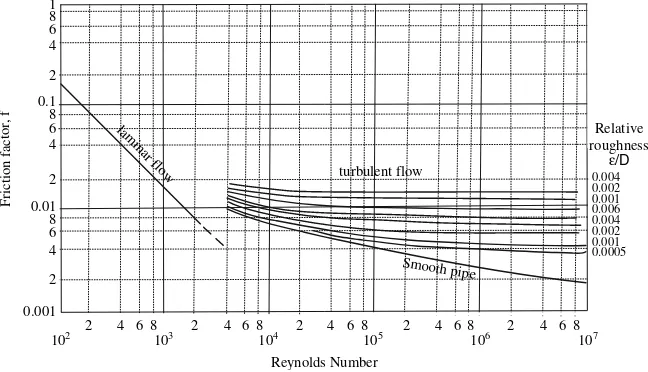
6. The friction factor f in turbulent flow can be obtained from the Moody chart.
7. In turbulent flow, the higher the surface roughness of the pipe the higher the influence of the Reynolds number on the friction factor f.
8. A sudden change of the fluid velocity in direction or magnitude causes friction losses.
9. Equation 6.1 gives the energy added to a fluid by a pump.
10. The energy added to a fluid by a pump is often called the developed head of the pump and is expressed in m.
11. The required power for a pump is independent of the liquid flow rate. 12. The brake power of a pump depends on the efficiency of the pump. 13. If the pressure in the suction of a pump becomes equal to the vapor pressure
of the liquid, cavitation occurs.
14. Under cavitation conditions, boiling of the liquid takes place in the pump. 15. The difference between the sum of the velocity head and the pressure head in the suction of the pump and the vapor pressure of the liquid is called available net positive suction head (NPSH).
16. To avoid cavitation, the available NPSH must be greater than the required NPSH provided by the pump manufacturer.
17. The higher the temperature of the liquid, the lower the available NPSH. 18. It is impossible to pump a liquid at its boiling point unless the pump is
below the liquid level in the suction tank.
19. Centrifugal pumps are usually self-primed pumps.
20. Positive displacement pumps are usually self-primed pumps.
21. Positive displacement pumps develop higher discharge pressures than cen-trifugal pumps.
22. The discharge line of a positive displacement pump can be closed without damaging the pump.
23. The discharge line of a centrifugal pump can be completely closed without damaging the pump.
25. The flow rate in a positive displacement pump decreases significantly as the head increases.
26. Centrifugal pumps are used as metering pumps. 27. Liquid ring pumps are usually used as vacuum pumps.
28. The capacity of a centrifugal pump is proportional to the rotational speed of the impeller.
29. The head developed by a centrifugal pump is proportional to the speed of the impeller.
30. The power consumed by a centrifugal pump is proportional to the cube of the speed of the impeller.
Examples
Example 6.1
A liquid food at 508C is being pumped at a rate of 3 m3/h from a tank A, where the absolute pressure is 12350 Pa, to a tank B, where the absolute pressure is 101325 Pa, through a sanitary pipe 1.5 in nominal diameter with 4:6105m surface roughness . The pump is 1 m below the liquid level in tank A and the discharge in tank B is 3.3 m above the pump. If the length of the pipe in the suction line is 2 m, the discharge line 10 m, and there are one 908 elbow in the suction line, two 908elbows in the discharge line, and one globe valve in the discharge line, calculate the power required, the developed head, and the avail-able Net Positive Suction Head (NPSH). Which of the three pumps that have the characteristic curves given below could be used for this pumping job? The viscosity and the density of the liquid are 0.003 mPas and 1033 kg/m3 respec-tively. The efficiency of the pump is 65%. Assume that the level in tank A is constant.
Solution
Step 1
Draw the process diagram:
Ws z1
z2 V2, P2
V1, P1
x
x 1
2
Level of reference A
Step 2
Calculate the mean velocity in the pipe: i) Calculate the mass flow rate,m:_
_
m¼Qr¼ 3m
3
h
1033kg m3
1 h
3600 s
¼0:861 kg=s
ii) Find the inside pipe diameter:
The inside pipe diameter of 1.5 in nominal diameter pipe is 1.402 in
D¼1:402 in0:0254 m
in ¼0:03561 m iii) Calculate the cross-section area of the pipe, A:
A¼pD
2
4 ¼
pð0:03561 mÞ2
4 ¼9:95910
4m2
iv) Calculate the mean velocity in the pipe, v:
v¼Q
A¼
3 m3=h
=ð3600 s=hÞ
9:959104m2
¼0:837 m=s
Step 3
Calculate the Reynolds number:
Re¼Dvr
m ¼
0:03561 m
ð Þð0:837 m=sÞ1033 kg=m3 0:003 kg=ms
ð Þ ¼10263
Step 4
Select two points, points 1 and 2, with known v, P, and z values to which to apply the mechanical energy balance equation. The pump must be between points 1 and 2.
Step 5
Calculate the frictional losses in the straight sections of the pipe, the elbows, and the valves that are between points 1 and 2:
i. Find the friction factor, f, for straight pipes. The friction factor f can be found from the Moody diagram (see Fig A.1 in the Appendix). If roughnesse¼0:000046m, the relative roughness is:
e
D¼
0:000046 m
0:03561 m ¼0:0013
Alternatively, f can be calculated by an empirical relationship e.g., the Colebrook equation:
1 ffiffi f
p ¼ 4log10
e=D 3:7 þ
1:255 Repffiffif
¼ 4log10
0:0013 3:7 þ
1:255 10263pffiffif
Solving the above equation by trial and error, find f¼0:0082.
ii. Find the equivalent length of a 908standard elbow: Le/D = 32, Equivalent length of straight pipe for 3 elbows:
Le¼3 32Dð Þ ¼3ð320:03561Þ ¼3:42 m
iii. Find the equivalent length of the globe valve: Le/D = 300:
Le¼300D¼3000:03561¼10:68 m
iv. Use the above results to calculate the frictional losses in the straight pipe sections, the elbows, and the valve:
hs¼4f
v2
2DL¼40:0082
0:8372 20:03561
m2=s2
m ð12þ3:42þ10:68Þm¼
¼8:42m
2
s2 ¼8:42
J kg
Units equivalence: m2
s2 ¼
m2N
s2N ¼
m mN s2N ¼
mJ s2N¼
mJ s2kgm=s2 ¼
J kg
Step 6
Calculate the frictional losses in the sudden contraction (entrance from the tank to the pipeline) from:
hc¼0:55 1
A2 A1 2 v2 2 2
A2=A1ffi0 since A1A2. Also,¼1 because the flow is turbulent. Therefore,
hc¼0:55 1
A2
A1
2
v22 2¼0:55
10:8372 21
m2 s2 ¼0:19
m2 s2 ¼0:19
J kg
Step 7
Calculate the total frictional losses:
Step 8
Apply the Mechanical Energy Balance Equation between points 1 and 2 in the diagram. Since the liquid level in the tank is constant, v1= 0:
ws¼
v2 2v21
2 þ
P2P1
þðz2z1ÞgþF¼
¼0:837
20
21 m2
s2 þ
10132512350 1033
Pa kg=m3
þð3:31Þm9:81m s2þ8:61
J kg¼
¼117:7 J kg
Units equivalence: Pa kg=m3¼
Pa m3
kg ¼ N m2 m3 kg¼ Nm kg ¼ J kg Step 9
Calculate the required power:
W¼ wsm_ ¼117:7
J
kg0:861 kg
s ¼101:33 J
s ¼ 101:33 W Since the efficiency of the pump is 65%, the required power (brake power) will be:
Wa¼
W Z ¼
101:33
0:65 ¼155:9 W
Step 10
Calculate the developed head Hm:
Hm¼
ws
g ¼
117:7 9:81
J=kg m=s2¼12:0
J N¼12:0
N m
N ¼12:0 m
Step 11
Calculate the available Net Positive Suction Head (NPSHa) using eqn (6.2): i. The total pressure in the suction tank is P = 12350 Pa.
iii. The frictional losses in the suction line are:
a) Frictional losses in the straight pipe section and the elbow of the suction line:
The straight pipe section of the suction line is 2 m.
The equivalent straight pipe length of one 908standard elbow for Le/ D=32, as found in step 5, is
Le¼1ð32DÞ ¼320:03561¼1:14 m
Therefore,
hss¼4f
v2
2DL¼40:0082
0:8372
20:03561ð2þ1:14Þ ¼1:01 J kg
b) Frictional losses in the entrance from the tank to the pipeline:
hc¼0:19J=kgðas calculated in step 6Þ
c) Total losses in the suction line:
Fs¼hssþhc¼1:01þ0:19¼1:2 J=kg
iv) Substitute values in eqn (6.2) and calculate NPSHa:
NPSHa¼
1235012349 10339:81 þ1
1:20
9:81¼0:88 m
Step 12
Select the pump:
Find the volumetric flow rate for each one of the pumps A, B, and C for a developed head of 12 m. Find also the required NPSH at the corresponding flow rate:
l Pump A: gives 1.6 m3/h and requires 0.20 m NPSH. Therefore, it does not give the required flow rate of 3 m3/h when the developed head is 12 m.
l Pump B: gives 3.1 m3/h and requires 1.05 m NPSH. Therefore, it gives the required flow rate of 3 m3/h, but requires more NPSH than the available of 0.81 m. If used, it will cavitate.
Q, m3/h
NPSH, m
Developed head, m
PUMP A
0 0 4 8 12 16 20 0 0.5 1 1.5 2 2.5
1 2 3 4 5
NPSH, m
Developed head, m
PUMP B
0 4 8 12 16 20 0 0.5 1 1.5 2 2.5
Q, m3/h
0 1 2 3 4 5
NPSH, m
PUMP C
0 4 8 12 16 20 0 0.5 1 1.5 2 2.5
Q, m3/h
0 1 2 3 4 5
Developed head, m
Exercises
Exercise 6.1
Water at 208C is flowing in a horizontal pipe 10 m long with 2 in inside diameter. Calculate the pressure drop in the pipe due to friction for a flow rate of 10 m3/h. Solution
Step 1
Calculate the mean velocity in the pipe:
i) Calculate the cross section area of the pipe:
ii) Calculate the mean velocity in the pipe, v:
v¼:::::::::::::::::::::::::::::::::::::::::::::::::::::::::::::::::::::::::::::::::::m=s
Step 2
Calculate the Reynolds number (find density and viscosity of water from a table with physical properties of water):
Re¼:::::::::::::::::::::::::::::::::::::::::::::::::::::::::::::::::::::::::::::::::::::::::::::::::::
Step 3
Calculate the pressure drop from the Fanning equation (since the flow is turbulent): i) Find the friction factor f from the Moody diagram or from Colebrook
equation:
f¼:::::::::::::::::::::::::::::::: ii) Calculate the pressure drop:
P¼4fL
D v2
2 ¼:::::::::::::::::::::::::::::::::::::::::::::::::::::::::::::::::::::::::::::Pa
Exercise 6.2
You have available a 550 W pump with 70% efficiency. Is it possible to use this pump to transfer 10 m3/h of a liquid through a 4.7 cm inside diameter pipe, from one open tank to another, if the liquid is discharged at a point 10 m above the liquid level in the suction tank and the total friction losses are 50 J/kg? The density and the viscosity of the liquid are 1050 kg/m3and 2 cp respectively. Solution
Step 1
Draw the process diagram. Step 2
State your assumptions.
:::::::::::::::::::::::::::::::::::::::::::::::::::::::::::::::::::::::::::::::::::::::::::::::::::::::::::::::::
Step 3
Select points 1 and 2. Step 4
Calculate the Reynolds number.
i) Calculate the cross section area of the pipe, A:
ii) Calculate the mean velocity in the pipe, v:
v¼::::::::::::::::::::::::::::::::::::::::::::::::::::::::::::::::::::::m=s
iii) Calculate the Reynolds number:
Re¼::::::::::::::::::::::::::::::::::::::::::::::::::::::::::::::::::::::::::::::::::::::
Since the flow is turbulent,a= ... Step 5
Apply the Mechanical Energy Balance Equation between points 1 and 2.
ws¼::::::::::::::::::::::::::::::::::::::::::::::::::::::::::::::::::::::::::::::::::::
¼:::::::::::::::::::::::::::::::::::::::::::::::::::::::::::::::::::::::::::::::::::::
::::::::::::::::::::::::::::::::::::::::::::::::::::::::::::::::::::::::::¼149 J kg
Step 6
Calculate the power.
Ws¼ wsm_ ¼::::::::::::::::::::::::::::::::::::::::::::::::::::::::::::::::::::::::::W
For a 70% pump efficiency, the required power (brake power) will be: WsR¼
::::::::::::::::::
::::::::::::::: ¼622 W
Since the required power is higher than the available 550 W, the pump is not suitable for this pumping job.
Exercise 6.3
A power-law fluid with consistency index K = 0.223 Pa s0.59, flow behavior index n = 0.59, and densityr= 1200 kg/m3is pumped through a sanitary pipe having an inside diameter of 0.0475 m at a rate of 5 m3/h from a tank A to a tank B. The level of the liquid in tank A is 2 m below the pump, while the discharge point is 4 m above the pump. The suction line is 3 m long with one 908elbow, while the discharge line is 6 m long with two 908elbows. Calculate the developed head and the discharge pressure of the pump. It is given that the pump is a self-priming pump.
Solution
Step 1
Ws
x2
Level of reference
x 1 A
B
3v3, P3
v2, P2
v1, P1 z1
z2
Step 2
Calculate the Reynolds number. i) Calculate the mass flow rate,m:_
_
m¼Qr¼:::::::::::::::::::::::::::::::::::::::::::::::::::::::::::::::kg=s ii) Calculate the cross-section area of the pipe, A:
A¼::::::::::::::::::::::::::::::::::::::::::::::::::::::::::::::::::::m2 iii) Calculate the mean velocity in the pipe, v :
v¼::::::::::::::::::::::::::::::::::::::::::::::::::::::::::::::::::::::m=s iv) Calculate the Generalized Reynolds number:
ReG¼
Dnv2nr
8n1 3nþ1 4n
n
K
¼
0:0475 m
ð Þ0:59ð::::::::::::::::m=sÞ20:59::::::::::::::::::kg=m3 :::::::::::::::::::::::::::::::::::::::::::::::::::::
¼:::::::::
Step 2
Calculate the frictional losses in the straight pipe sections, the elbows, and the valve.
i) Find the friction factor f.
1 ffiffi f
p ¼ 4
n0:75log10 ReGð Þf 1n
=2
0:4
n1:2 ¼::::::::::::::::::::::::::::::
:::::::::::::::::::::::::::::::::::::::::::::::::::::::::::::::::::::::::::::::::::::::::::
ii) Find the equivalent length of a 908standard elbow: Le=D¼32
Equivalent length of straight pipe for 3 elbows: Le¼:::::::::::m
iii) Find the equivalent length of the globe valve: Le=D¼300
Equivalent length of straight pipe for 1 globe valve Le¼:::::m
iv) Calculate the frictional losses in the straight pipe sections, the elbows, and the valve:
hs¼:::::::::::::::::::::::::::::::::::::::::::::::::::::::::::::::::::::::::::::::::
::::::::::::::::::::::::::::::::::::::::::::::::::::::::::::::::::::::::::::::::::::::: J kg
Step 3
Calculate the frictional losses in the sudden contraction.Since the flow is laminar, the kinetic energy correction coefficient is:
a¼ð2nþ1Þð5nþ3Þ
3 3nð þ1Þ2 ¼:::::::::::::::::::::::::::::::::::::::::::::::
hc¼::::::::::::::::::::::::::::::::::::::::::::::::::::::::::::::::::::::::::::::
J kg
Step 4
Calculate the total frictional losses.
Ft¼::::::::::::::::::::::::::::::::::::::::::::::::::::::::::::::::::::::::::::: J kg
Step 5
ws¼
¼:::::::::::::::::::::::::::::::::::::::::::::::::::::::::::::::::::::::::::::::::::::::::::¼
¼::::::::::::::::::::::::::::::::::::::::::::::::: J kg
Step 6
Calculate the required power.
Ws¼ wsm_ ¼::::::::::::::::::::::::::::::::::::::::::::::::::::::::::::::: W
For a 70% pump efficiency, the required power (brake power) will be:
Wa ¼
Ws
Z ¼::::::::::::::::::::::::::::::::::::::::::: W Step 7
Calculate the developed head Hm.
Hm¼
ws
g ¼:::::::::::::::::::::::::::::::::::::::::::::::::::::::::::::::::m Step 8
Calculate the discharge pressure.Apply the Mechanical Energy Balance Equa-tion (MEBE) between points 2 and 3 with v2 ¼v3, z3¼0, and ws¼0:
P3
r ¼ P2
r þz2gþFd where Fd= the friction losses in the discharge line.
P3¼::::::::::::::::::::::::::::::::::::::::::::::::::::::::::::::::::::::::::::::::::::::¼
¼::::::::::::::::::Pa
Exercise 6.4
Study the spreadsheet program given inPump.xlsto get familiar with the way the program works. Modify the spreadsheet program given inPump.xlsto solve Example 6.1:
b) if the pump is 1 m above the liquid level in the suction tank (is this pumping possible?); and
c) If the required NPSH is 1 m and the absolute pressure in tank A is 101325 kPa, how many meters below the pump could the suction level be without having cavitation problems? If the pump was pumping water at 218C from a well, how many meters below the pump could the suction level be without having cavitation problems?
Exercise 6.5
Heat Transfer by Conduction
Theory
As with all transport phenomena, the rate of the transferred quantity is propor-tional to the driving force and inversely proporpropor-tional to the resistance. For heat transfer by conduction, the driving force is the temperature differenceT and the resistance R¼x=kA, wherex is the wall thickness, k is the thermal conductivity and A is the surface area perpendicular to the direction of transfer. For a cylindrical wall, A is equal to the logarithmic mean surface area, while for a spherical wall, A is equal to the geometric mean surface area. Thus:
Rate of heat transfer
For a single wall
q¼T
R For a composite wall
q¼PT
R
Resistance to heat transfer
Resistance, R Surface area, A
Plane wall x=kA A
Cylindrical wall r=kALM ALM¼
A1A2
ln A1=A2
Spherical wall r=kAG AG¼ ffiffiffiffiffiffiffiffiffiffiffiffiA1A2
p
Review Questions
Which of the following statements are true and which are false?
1. Heat is conducted in solids, liquids, and gases by the transfer of the energy of motion from one more energetic molecule to an adjacent less energetic one.
S. Yanniotis,Solving Problems in Food Engineering. ÓSpringer 2008