W2O: Methodology for the Conversion of Workflows into
an Essential Object Model.
Horacio Pendenti1, Rodolfo Bertone2, Pablo Thomas3
School of Engineering – UNPSJB (Ushuaia Delegation) Instituto de Investigación en Informática LIDI (III-LIDI)4
School of Computer Science - UNLP
Abstract. The objective of this paper is the construction of an Essential Object Model for Information Systems. This model is derived from the organization workflows representing the business processes and follows rules described by the methodology proposed. To achieve the desired results, the methodology proposes two phases: process specification, to produce the business model, and generation of the Essential Object Model based on the business model obtained before. The leading threads of this methodology are: requirement elicitation and specification based on business model knowledge and information flow; tool background, use of common methods, and RUP-based development. The end result is a conceptual Essential Object Model with application flow and control separated from application logics.
Keywords: Software Engineering, Business Software Process, Object Modeling, Workflow.
1
Introduction
Based on the experiences carried out on the software process, it can be noted that one of the most frequent problems that still lacks an efficient solution is providing this process with the possibility of adapting in a fast and easy manner to the constant changes of requirements, and therefore, specifications. In this sense, one of the greatest difficulties of Software Engineering is obtaining clear and correct specifications. On the other hand, there is the problem of how to handle the changes introduced into the rules that govern business in the context of the current operating dynamics. The list of problems that contribute to worsen this situation is larger, but of note is also how to adapt the systems to new technologies. Environment dynamics also affect work teams, since changes in the composition of software equipment are
1 {[email protected]} UNPSJB - School of Engineering, Ushuaia Delegation. 2 {[email protected]} Full-Time Head Professor, UNLP - School of Computer Science.
3 {[email protected]} Full-Time Associate Professor, UNLP - School of Computer Science.
usually frequent and have a great impact on small work teams, so this is another issue that requires attention.
These aspects ultimately affect costs. In this regard, Somerville [1], presents a thorough assessment of the problem of changes, providing relative costs and reaching the conclusion, among others, that “The cost of software changes usually exceeds the
cost of software development.” Therefore, it is common that, in order to reduce
change management costs, a non-harmonic increase of the effort put into the various aspects of the software process is applied.
Despite the efforts carried out from the Software Engineering arena, they often are insufficient because a sizeable investment in resources is required to solve the problems caused by these situations. For this reason, it is crucial to have an efficient change administration strategy to adapt to new technologies and change dynamics.
The problem described is supported by countless studies, where Business Modeling through Processes is seen as a way of improving the software process. There is currently a large number of publications and studies dealing with this topic, for instance, RUP models a business based on usage cases and activity diagrams, or Jablonski's proposal [2], who supports the solution by means of business process modeling with workflows and proposes a methodology for the development of WfMS.
For these reasons, a unified approach to find solutions that allow achieving a flexible, effective, organized and as efficient as possible change should be sought. This methodology presents a simple way to obtain an essential model of the object-oriented system but maintaining the consistency between the products involved in the requirements and analysis gathering and specification stages.
2
Objective
As already mentioned in the abstract, the objective proposed is building an Essential Object Model (EOM) of an Information System (IS) based on an organization's business processes, which are surveyed as workflows, following the guidelines established by this methodology.
The leading threads of this methodology are:
Requirement Collection and Requirement Specification mostly based on the knowledge of business processes and information flow.
This process is supported by known and proven tools and methods.
The development stage follows general RUP guidelines; this model is also used as a comparative reference.
The end result of this methodology is a conceptual model where flow and control on the one hand are clearly separated from application logics on the other, as shown in Fig. 1.
Fig. 1. W2O architecture – Control and information components separated from application logics.
Some of the expected benefits of having an executable business model are: organizational discipline, fast reaction to internal and environmental changes, lower maintenance costs, self-documented model and system, simple process re-engineering, resource and system integration, and business re-engineering.
3
Proposed methodology
Before discussing the analytical development, a general representation of the methodology is presented in Fig. 2, including a detail of phases, stages and activities.
[image:3.595.126.471.531.670.2]3.1 Phase 1. Specification of business processes by means of workflows.
The specification of business processes is used to build a model that represents organization-critical processes, and is called third-level process model (3PM). To this end, the following stages are required:
Stage 1. Process identification and definition. During this stage, the core processes of the organization are detected, identified, and described at a conceptual level. Process identification is a joint task shared by IT professionals and experts from the organization and analysts. According to Van Der Aalst, a process can be defined as follows: a process consists of a number of tasks that have to be carried out and a set
of conditions that determine the order of the tasks [3].
The activity begins with the definition of a list of tasks provided by the experts, expressed as the actions that they perform. These are recorded in natural language, observing a certain level of formality where each task is described in a very short phrase with at least one main verb denoting the action that is carried out. Each defined task (process) is assigned a code (PID) and a simple name that describes the purpose of the task. This task denomination method allows generating organization business processes. Some examples are included in Table 1.
Table 1. Examples of processes and their identification.
List of identified tasks Name of process assigned Purchase / Buy monthly supplies p1. Purchase
Sell / Sell goods/services p2. Sell
Analyze feasibility p3. Feasibility analysis Analyze the system p4. Analysis / System analysis Withdraw money from an account p5. Withdrawal
Afterwards, each process receives a brief and an extended, narrative description. Then, all processes included in the preliminary list go through a validation process. This validation process consists in detecting overlapping, complex, missing, etc., processes by reviewing and redefining them as many times as it is necessary until a complete business process list is obtained. To end this stage, an entry corresponding to each process is generated as a new workflow in the WfMS application being used.
It can be seen that the solutions provided by WfMS's are a very limited IS mainly based on messages and control signals. Basically, the WfMS-W2O is the main interface of the organization IS. This means, among other aspects, that all systems need an interface with WfMS-W2O and the human interface is almost exclusively with the WfMS-W2O. Thus, the IS is almost the same as the WfMS-W2O, whose logic implementation is in the other systems.
It should be noted at this point that the workflows to be used in this methodology have special characteristics, mainly as regards information flow; therefore, they will be referred to as CIW (Control and Information Workflow) in W2O.
Stage 2. Identification and definition of process tasks. The purpose of this stage is detecting and defining all tasks that are part of each process and their correct placement within the corresponding CIW. To this end, the following is required:
Detecting all of the tasks that are part of the process, classifying them, assigning a name to each of them, describing them, validating them, and appropriately placing them within the CIW.
Assigning responsible areas or actors for the execution of each task.
Completing each process's CIW by adding and connecting all tasks to each other. As tasks are detected, they are recorded on the Tasks Table (TT) [Table 2] with a simple name and a task identifier (TID). The name of a task must be a very simple sentence that has meaning on its own and is formed by a verb followed by one or more nouns. The presence of more than one noun in the name will determine the relationships between essential objects.
At a following step, organizational units that are in charge of roles and are responsible for the execution of the tasks are detected. Once defined, they are coded (RID), a simple name is assigned to them, and they are recorded in the List of Responsible Parties (RL) [Fig. 4]. Finally, the agents that will be in charge of executing the tasks are selected and recorded on the RL.
The third step consists in recording two descriptions of the defined tasks – a brief description and an extended one. The former is a description of the purpose of the task, no longer than one or two lines, whereas the latter is a narrated description [4] including all information about the task available so far. From a practical viewpoint, it can be said that the content of this record is a conceptual description of what has to be done to achieve the objectives of the task, which information is used, when the task is done, who is in charge of performing the task, and what is the minimum, estimated, and maximum duration of the task, among other aspects.
As a final step in this stage, the task model implicitly defined so far has to be consolidated, the same as the process model was validated before. Some of the problems to be solved during validation are: absence, overlapping, correspondence, sequencing, duplicity, huge-task, small-task, and completeness of tasks.
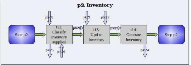
At the end of this stage, CIWs, which are in a way a summary of the development so far, have to be graphically represented in the WfMS [Fig. 3].
The main product of this stage is the 2PM or second-level process model, which includes a detail of all the tasks required to execute the processes and indicates who is responsible for their execution.
Stage 3. Normalized specification. The purpose of this stage is building the Dictionary of Dynamic Information (DDI) and formally identifying the subtasks for each task.
The DDI is a new element that is incorporated into the business model. The conceptual difference between a DDI and a DD is that, whereas the former is a
representation that works “dynamically” on the CIW's, the latter is a static representation of the “static” data model of the system.
unique number in the system. The last step before recording the PK's in the DDI consists in indicating their origin and destination. The origin of a PK is unique, be it a task (TID), the environment (E) or a responsible party (RID), whereas the destination can be one or more tasks that can be combined with the environment and/or one or more responsible parties or not. Finally, the composition of PK's is specified, they are recorded on the DDI, and the CIW is updated accordingly.
The second activity in this stage is detecting and identifying all subtasks within each task that are required in order to complete the corresponding task. Subtask identification begins by listing all activities (which then become subtasks) that are necessary to perform the task. To do this, the same naming conventions used for tasks are followed, i.e., an action denoted by a verb followed by one or more nouns are used. The syntax and grammar of these names is then analyzed to detect the essential objects of the domain and the relationships between them. Each identified subtask is for the time being unique, at least within the task where it is defined, and it is coded with the format st#. Finally, they are recorded in the Tasks Table.
As already mentioned, the names assigned to subtasks must be simple and
declarative syntactic constructions, or “kernel sentences”, as summarized by Carasik
et al. [5]: - They use common nouns - They use unmarked mood (indicative), voice (active) and polarity (affirmative) - They do not contain optional or omissible expressions.
[image:6.595.151.457.423.527.2]The result of this stage is the third-level process model (3PM), composed by: the CIW's [Fig. 3], the RL [Fig. 4], the TT [Table 2], and the DDI.
Fig. 3. CIW corresponding to the Process p2 - Inventory.
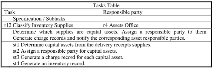
Table 2. Tasks Table with subtask names, partial view.
Tasks Table
Task Responsible party
Specification / Subtasks
t12 Classify Inventory Supplies r4 Assets Office
Determine which supplies are capital assets. Assign a responsible party to them. Generate charge records and notify the corresponding asset responsible parties.
st1 Determine capital assets from the delivery receipts supplies. st2 Assign a responsible party for capital assets.
st3 Generate a charge record for each capital asset. st4 Generate an inventory record.
3.2 Phase 2. Methodology for obtaining an Essential Object Model from CIW’s.
[image:7.595.123.475.167.281.2]The purpose of the second phase is obtaining the Essential Object Model (EOM) of the organization from the third-level process model obtained during the first phase. The EOM is considered as the set of core objects of the IS and their relationships, which can be detected from the business model. The EOM has a graphical representation that is similar to that of a RUP class diagram [6] [7] and an analytical representation that consists of tables.
Table 3. Relationship between RUP artifacts and W2O products.
RUP
Relationship W2O
Artifact Workflow Product Phase
Business model Business modeling
equivalent 3PM
1: BM + Requirements Use case model Requirements
Conceptual object model Analysis EOM 2: Analysis
Stage 1. Define essential objects. First, a list of the information system's essential objects has to be built. From an analysis standpoint, it can be said that these objects are the domain objects of the problem. To start building this list, Chen's concepts [8] [9] and Wirfs-Brock's recommendations [4] are applied to the business model, analyzing each subtask name and detecting which are the nouns that become candidate objects and recording them on the Candidate Objects List (COL). Chen's concepts are mostly followed due to their simplicity and proven practical success. For instance, Wirfs-Brock's methodology [4] analyzes the narrated descriptions to extract from them candidates to be considered as objects and implicitly uses the same concept in its grammar analysis.
The second activity consists in correcting and purging the COL to obtain the List of Essential Objects (LEO) [Table 4]. To do this, the COL, the DDI and the specifications of the tasks included in the TT are used. The activity consists in removing those candidates to essential object that are too weak, detecting new objects, and eventually correcting the names of the objects that are strong candidates.
Stage 2. Build the Essential Object Model. In this stage, the Essential Object Model of the IS is finished and all final details are added. First, based on the TT, the Normalized Subtask Table (NST) [Table 5] is built in a similar way as the other sub-products of the methodology, particularly the LEO. The purpose of the NST is simplifying the identification of the objects that are part of the Essential Object Model.
Secondly, the relationships between the essential objects of the domain model have to be detected and identified, and their cardinality specified. To this end, the Table of Relationships (TR) [Table 6] is built by applying re-engineering tasks to the NST, such as: recognition, simplification and codification of the relationships that are implicitly contained in the NST. The guidelines to obtain the relationships and their cardinality are taken from RUP, which refers to them as associations and multiplicity, respectively [10].
Then, objects have to be classified identifying eventual super-types, following RUP guidelines as well. This step finishes by adding the "super-type" attribute to the LEO for each essential object.
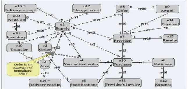
[image:8.595.142.465.423.577.2]The last step consists in drawing the Essential Object Diagram (EOD) [Fig. 5] and performing a final validation. The EOD represents the essential objects and their relationships, cardinality, and classification. In the practice, the EOD of W2O is equivalent to a Class Diagram in RUP; therefore, all guidelines for building the latter can be applied to an EOD, taking into account all relevant exceptions, such as dependencies, restrictions, operations and a class of properties such as attributes [6] [10].
Fig. 5. EOD, example of an Essential Object Diagram.
The result of the second phase is the Essential Object Model (EOM), which includes: the EOD, the LEO, the NST and the TR.
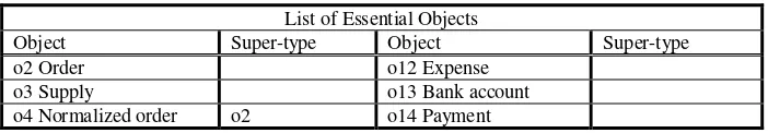
Table 4. List of Essential Objects with classification, partial view.
List of Essential Objects
Object Super-type Object Super-type
o2 Order o12 Expense
o3 Supply o13 Bank account
o4 Normalized order o2 o14 Payment
Table 5. Normalized Subtask Table (NST), partial view.
Tasks Table
Task Responsible party
Specification / Subtasks
t12 Classify Inventory Supplies r4 Assets Office
Determine which supplies are capital assets. Assign a responsible party to them. Generate charge records and notify the corresponding asset responsible parties.
st1 Determine the capital asset in (o3) Supply of (o16) Delivery receipt. st2 Assign (o1) responsible Area of (o3) Supply capital asset.
st3 Generate (o17) Charge record for (o3) Supply of capital asset to the (o1) Area to which it is delivered.
st4 Generate record of (o18) Inventory.
Table 6. Table of Relationships (TR), partial view.
Table of Relationships
Relationship Relationship
rr10 (o8) Offer (o7) Provider. [n : 1] rr23 (o18) Inventory (o3) Supply. [1 : n] rr11 (o8) Offer (o3) Supply. [n : n] rr24 (o3) Supply (o19) Transfer. [1 : n]
4
Conclusions
By means of an example, it was possible to establish that the methodology is effective for the objective proposed and can be used as a guide that allows obtaining the desired results – the 3PM and the EOM.
The inference of an Essential Object Model from a business model is not a fully automatic process, since the specifications used to build the former are not expressed in formal notation. The method developed to perform this pseudo inference introduces restrictions and rules that induce an object mapping process that allows translating one model into another.
Also, a business model that is fully mapped in a design / implementation model is obtained.
5
Future work
There are basically two well-defined lines of work. One of them, derived from the EOM, is considered by other proven methodologies that reach the final results of the software process.
The other line of work, derived from the 3PM, opens in turn several lines of analysis and action, among which the following can be highlighted:
DDI: Mainly regarding the representation of semantic aspects. Building a WfMS-W2O.
Interface applications ↔ WfMS-W2O. Interface WfMS-W2O ↔ environment.
Security: In WfMS, security is an issue that has not been dealt with in depth. Formalization: A formal specification of the 3PM would be of great value, following what Hamed et al. [11] did.
6
References
1. Somerville, I.: Ingeniería de software, 6a edición. Pearson Educación (2002).
2. Jablonski, S.: On the complementarity of workflow management and business process modeling. ACM SIGOIS Bulletin, vol. 16, Issue 1, pp. 33--38. ACM. Digital Object Identifier 10.1145/209891.209899 (1995).
3. Van der Aalst, W., Van Hee, K.: Workflow Management: Models, Methods, and Systems. The MIT Press (2004).
4. Wirfs-Brock, R., Wilkerson, B., Wiener, L.: Designing Object Oriented Software. Prentice Hall, Inc. (1990).
5. Carasik, R.P., Johnson, S.M., Patterson, D.A., Von Glahn, G.A.: Domain description grammar: application of linguistic semantics. ACM SIGSOFT Software Engineering Notes, vol. 15, Issue 5, pp. 28--43. ACM. Digital Object Identifier 10.1145/101328.101335 (1990). 6. Jacobson, I., Booch, G., Rumbaugh, J.: El Proceso Unificado de Desarrollo de Software.
The Addison-Wesley Object Technology Series. Pearson educación S.A. (2000).
7. Booch, G., Rumbaugh, J., Jacobson, I.: The Unified Modeling Language User Guide. The Addison-Wesley object technology series. Addison Wesley (1999).
8. Chen, P.P.: The entity-relationship model - toward a unified view of data. ACM Transactions on Database Systems, vol. 1, issue 1, pp. 9--36. Digital Object Identifier 10.1145/320434.320440 (1976).
9. Winslett, M.: Peter Chen speaks out: on paths to fame, the roots of the ER model in human language, the ER model in software engineering, the need for ER databases, and more. ACM SIGMOD Record vol. 33, issue 1, pp. 110--118. ACM. Digital Object Identifier 10.1145/974121.1345032 (2004).
10.Fowler, M: UML Distilled: A Brief Guide to the Standard Object Modeling Languaje (3rd Edition). The Addison-Wesley Object Technology Series. Pearson Education, Inc (2004). 11.Hamed, H., Salem, A.: UML-L: An UML Based Design Description Language. Computer