ICSE2002 Proc. 2002, Penang, Malaysia
Pipeline Floating Point
ALU
Design using VHDL
M a m u Bin Ibne Reaz, M E E E , Md. Shabiul Islam, MEEE, Mohd. S. Sulaiman, MEEE Faculty of Engineering, Multimedia University, 63 100 Cybejaya, Selangor, Malaysia
Abstract A pipeline floating point arithmetic logic unit (ALU) design using VHDL is introduced. The novelty of the ALU is it gives high performance through the pipelining concept. Pipelining is a technique where multiple instruction executions are overlapped. In the top-down design approach, four arithmetic modules: addition, subtraction, multiplication, a n d division:
are combined
to
form the floating-point ALU. Each module is divided into smaller modules. Two bits selection determines which operation takes place at a particular time. The pipeline modulesare
independent of each other. Allthe modules in t h e ALU design a r e realized using VHDL. Design functionalities a r e validated through simulation and compilation. Test vectors a r e created to verify t h e outputs
as
opposed to the calculated results. Besides verifying the outputs, the outputs' timing diagram and interfacing signals are also tracked to ensure that they adhereto
the design specifications. Successful implementation of pipelining in floating pointALU using VHDL fulfills the needs for different high-performance applications.
I. INTRODUCTION
Floating-point numbers
are
widely adopted in many applications due to its dynamic representation , capabilities. Floating-point representation is able to retain its resolution and accuracy compared to fixed-point representations. IEEE specified theIEEE
754 standard for floating-point representation in 1985 [I]. Based on .this standard, floating-point representation for digital systems should be platform-independent and data are interchanged 6eely among different digital systems.ALU is a block in a microprocessor that handles arithmetic operations. It always performs computation of floating-point operations. Some CPUs such as AMD Athlon have more than one floating point unit that handles floating point operations [2]. The AMD Athlon processor boasts an FPU count of three, which in an indirect way reiterates the importance of the
inclusion of floating-point operations in a microprocessor's functionality [3].
Pipelining is one of the popular methods to realize high performance computing platform. It was first introduced by IBM in 1954 in Project Stretch. Implementing pipelining requires various phases of floating-point operations be separated and be pipelined into sequential stages. This increases the throughput and efficiency of the overall operation. Hence to realize an ALU design , we propose a pipeline floating point
ALU design using VHDL to ease
the description, verification, simulation and hardware realization. VHDL is a widely adopted standard and has numerous capabilities that are suited for designs of this sort. The use of VHDL for modeling is especially appealing since it provides formal description of the system and allows the use of specific description styles to cover the different abstraction levels (architectural, register transfer and logic level) employed in the design [4].11. MATERIALS AND METHODS This paper describes the implementation of pipelining in design the floating-point ALU using VHDL. In order to design a number of sub-
objectives that support and supplement the main. objectives are defined. The sub-objectives are to design
a
32-bit (single precision) floating-point ALU operating on the IEEE 754 standard floating-point representations, supporting the four basic arithmetic operations: addition, subtraction, multiplication and division. Second sub-objective is to model the behavior of the ALU design using VHDL.Below are the specifications for a 32-bit (single precision) floating-point ALU design:
I . Input 'A', 'B', and output 'Results' are 32-bit
binary floating-point (single precision). ii.Operands A and B operate as follows:
A (opsation) B = Results
~ WkreDpErationcanbeMdilion(i).SubVartion (-), ~ Multlpkadion (').and Divirbn (0
. ..- - .- .. ~.~ ~~~~~ -~ ~.
ICSE2002 Proc. 2002, Penang, Malaysia
_ _ _ _ _ ?
~ Seldtionr I ~ O l - d . - & i
I m -A,*. i lo-l*lh*. I
i
iv.'Status' a 4-bit output signal. It notifies the I ll-dbi&m
state of the arithmetic results as$ollows:
Y. Only the module that is selectedusing a demux
apply the clock cycle and saves it.
vi. Concurrent processes are used to allow processes to run in parallel, hence pipelining.
U ,.s
. . . ~ , . . . . . . ... ...
Fig. 1 Top level view of the ALU design ALU is separated into smaller modules: addition, subtraction, multiplication, division, demux and mux (selector). Each arithmetic module is further divided into smaller modules that are coded individually. Fig. 1 shows the top level view of the ALU. It consists of four functional arithmetic modules, three demultiplexers and two multiplexers. The
demultiplexers and multiplexers are used to route input operands and the clock signal to the correct functional modules. They also route outputs and status signals based on the selector pins.
After a module completes its task, outputs and status signals are sent to the muxes where they multiplexed with other outputs from corresponding modules to produce output result.
Selector pins are routed to these muxes such that only the output from the currently operating functional module is sent to the output port. Clock is specifically routed rather than tied permanently to each module since only the selected functional modules need clock signals. This provides power savings since the clock is
supplied to the required modules only and avoid invalid results at the output since the clock is used as a trigger in every process.
Pipelined Floating Point Addition Module Addition module has two 32-bit inputs and one
32-bit output. Selection input is used to enable or disable the module. Addition module IS further divided into 4 small modules: zero check, align, add-sub, and normalize modules. Fig. 2 shows the pipeline structure of the addition module.
Fig. 2 Pipeline structure of the addition module Zero checkModule
This module detects zero operands early in the operation and based on the detection result, it asserts two status signals. This eliminates the
need
of subsequent processes to check for the presence of zero operands. Tab. 1 summarizes the algorithm.Tab. 1 Setting of zero-check stage status signals
In align module, operations are performed '
.
Align Modulebased on status signals from previous stage. Zero-operands are checked in the align module as well. The module introduces implied bit into the operands that illustrated in Tab. 2.
0 IX(Do.'tWei I 0 I I
1 1 1 I 0 1
I I 0 I 1 I 0
Tab. 2 Setting of the mplied bit
Add-sub Module
ICSE2002 Proc. 2002, Penang, lvlalaysia
of the mantissa that is summarized in Tab. 4. A cany bit, introduced here, is tagged to the MSB of the result's mantissa. This gives an extra bit of precision and is useful for calculations involving a carry generation. The results are assigned to a-stage3. Status signal is set to 1 to indicate the need for normalization by the next stage.
Tab. 3 Preliminary checks for add-sub module
Tab. 4 add-sub operation and sign fixing Normalize Module
Input is normalized and packed into the
IEEE754 floating-point representation. If the norm status signal is set, normalization is performed otherwise the implied and the cany bits at the mantissa's MSB is dropped. The result is then packed into the IEEE754 format and assigned to the output port. If norm is set, the module checks mantissa 1's MSB. This implies the cany bit is set and no normalizationis needed The carry bit is now the result's implied bit, which is dropped. The remaining bits are packed and assigned to the output port.
If c q bit is 0: normalization is carried out. Normalization module sets mantissa's MSB to 1 The current mantissa is shifted left until a 1 is encountered. For each shift the exponent is decreased by 1. Thus if the MSB of the mantissa is 1, then normalization is complete and the fmst bit, the implied bit, is dropped. The remaining bits are packed and assigned to the output port. Pipelined Floating Point Subtraction Module
Subtraction module has two 32-bit inputs and one 32-bit output. Selection input is used to enableidisable the entity depend on the operation. Subtraction module is divided further into four small modules zero check module, align module, add-sub module and normalize module. The subtraction algorithm differs only in the add-sub module where the subtraction operator change the sign of the result. The remaining three modules are similar to those in the addition module. Tab. 5 and Tab. 6 summarize the
preliminary checks and sign fixing respectively for subtraction module.
Tab 5 Preliminary checks for add-sub module
Tab. 6 add-sub operation and sign fixing Pipelined Floating Point Multiplication Module
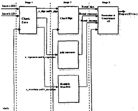
Multiplication entity has three 32-bit inputs and two 32-bit outputs. Selection input is used to enable or disable the entity. Multiplication module is divided into check zero, check sign, add exponent, and normalize and concatenate all modules, which are executed concurrently. Status signal indicates special result cases such as overflow, underflow and result zero. In this project, pipelined floating point multiplication is divided into three stages (Fig. 3). Stage 1 checks whether the operand is 0 and report the result accordingly. Stage 2 determines the product sign, add exponents and multiply fractions. Stage3 normalize and concatenate the product.
Fig. 3 Pipeline structure of the multiplication module Check Zero module
ICSE2002 Roc. 2002, Penang, Malaysia
the operands is zero, the zero-flag is set to 1. The output results zero, which is passed through all the stages and outputted. If neither of them are zero, then the inputs with IEEE754 format is unpacked and assigned to the check sign, add exponent and multiply mantissa modules. The mantissa is packed with the hidden bit ‘I’
Add exponent module
The module is activated if the zero flag is set.
Else, zero is passed to the next stage and exp-flag is set to 0. Two extra bits are added to the exponent indicating overflow and underflow. The resulting sum has a double bias. So, the extra bias is subtracted from the exponent sum. After this, the exp-flag is set to 1
Multiply mantissa module
In this stage zero-flag is checked fust. If the zero-flag is set to 0, then no calculation and normalization is performed. The mant-flag is set to 0. If both operands are not zero, the operation is done with multiplication operator. Mant-flag is set to 1 to indicate that this operation is executed. It then produces 46 bits where the lower order 32 bits of the product are truncated.
Check sign module
This module determines the product sign of two operands. The product is positive when the two operands have the same sign; otherwise it is negative. The sign bits are compared using an XOR circuit. The sign-flag is set to 1.
Normalize and concatenate all module This module checks the overflow and underflow after adding the exponent. Underflow’ occurs if the 9’ bit is 1. Overflow occurs if the 8 bits is 1. If exp-flag, sign-flag and mat-flag are set, then normalization is carried out. Otherwise, 32 zero bits are assigned to the output.
During the normalization operation, the mantissa’s MSB is 1. Hence, no normalization is needed. The hidden bit is dropped and the remaining bit is packed and assigned to the output port. Normalization module set the mantissa’s MSB to I. The current mantissa is shifted left until a 1 is encountered. For each shift the exponent is decreased by 1. Therefore, if the mantissa’s MSB is 1, normalization is completed and fust bit is the implied bit and dropped. The remaining bits are packed and assigned to the output port. The fmal normalized product with the correct biased exponent is concatenated with product sign.
Pipelined Floating Point Division Module
Division entity has three 32-bit inputs and two 32-bit outputs. Selection input is used to enable or disable the entity. Division module is divided into six modules: check zero, align dividend, check sign, subtract exponent, divide mantissa and normalize concatenate modules. Each module is executed concurrently. Status indication is used to indicate special result cases such
as
overflow, underflow, result zero and divided by zero. Fig. 4 shows the pipeline structure of the division module.Fig. 4 Pipeline structure of the division module Check Zero module
The two operand are checked to determine if either one contains a 0 value. Dividend operand being a zero indicates an attempt to divide by 0, which is an illegal operation. Z-flag is then set. Four bits indicator is implemented to indicate these enors. If neither of the operands is equal to 0 then the inputs with IEEE754 format is mpacked and assigned to the check sign, subtract exponent and align mantissa modules. The mantissa is pack with the hidden bit ‘1’.
Check sign module
Check sign module performs the same Align dividend module
Align dividend module compare both mantissas. If mant-a is greater than or equal to the value of man-b, then the mant-a must be
aligned. For every bit right shift of mant-a mantissa, the man-a exponent
is
then incremented by 1. This increase may result in an exponent overflow, in this case an overflow flag is set. Otherwise, the process continues with the parallel operations of exponent subtraction and mantissa division. Align-flag is set to 1.operation as in the multiplication module.
Subtract exponent module
ICSE2002 h o c . 2002, Penang, Malaysia
the exponent to indicate overflow and underflow. Here two exponents are subtracted. The bias is added back. After this, the exp-flag is set to 1.
Divide mantissa module
In this stage, align flag is checked first. If align flag is 0 then no mantissa division is performed. Mant-flag is set to 0. If both operands are not zero, man-a is divided by mant-b. In division algorithm, comparison between two mantissas is done by subtracting the two values and checking the output sign.
111.
SIMULATION
AND DISCUSSIONDesign is verified through simulation, which is done in a bottom-up fashion. Small modules are simulated in separate testbenches before they are integrated and tested as a whole. All four arithmetic operations available in the design are tested with the same inputs. The sequence of operations done in the simulation is addition, subtraction followed by multiplication and then division. The results of operation on the test vectors are manually computed and are referred to as expected result, later compared with the simulation results. -The generated outputs are in hexadecimal form. All hexadecimal values are converted back to the decimal format "and tabulated in the various tables below.
Addition
" J ,.,.
-
I_Multiolication
oumm now I 4 1 I d W W *
Emartadoarer I 4s ~WPWDOD
N .
CONCLUSIONBy simulating with various test vectors the proposed approach of pipeline floahng point
ALU
design using VHDL is successfully designed, implemented, and tested. Currently, weare conducting further research that considers the
further reductions in the hardware complexity in termsof
synthesis and fually download the code into Altera FLEXlOK: EPFlOKIOLC84 FPGA chip on LC84 package for hardware realization.REFERENCES
[IIANSIWEE Std 754-1985, IEEE Stundord for
Binory Flooring-Point Arithmetic, IEEE, New
York, 1985.
[2]M. Daumas, C. Finot, "Division of Floating Point Expansions with an Application to the
Computation of a Determinant", Journal o/ Universol Compurer Science, vo1.5, no. 6, pp. 323- 338, June 1999.
[ 3 ] A M D Athlon Processor techmcal brief, Advance Micro Devices Inc., Publication no. 22054, Rev. D, Dec. 1999.
[ 4 ] S . Chen, B. Mulgeew, and P. M. Grant, "A
clustering techmque for digital communications channel equalization using radial basis function networks,'' IEEE Trans. Neural Networks, vol. 4,