An approach to patents of prestressed concrete in 20th Century's arquitecture
9
0
0
Texto completo
(2) An approach to patents of prestressed concrete in 20th Century’s architecture M. P. Llorente Zurdo & J. Anaya Díaz Universidad Politécnica de Madrid, Escuela Técnica Superior Arquitectura Madrid. Spain. M. de Miguel Sánchez Universidad de Alcalá de Henares, Escuela Técnica Superior de Arquitectura y Geodesia. ABSTRACT: Around 1906, there was a discussion in the various publications on reinforced concrete about the problem of how to avoid the cracks on it, due to tension that occurred inside. First attempts to avert it failed since the tension applied to the steel was lost with the passage of time, as much for the hydraulic retraction of the concrete as for the use of not very high strength steels, and also because of the stress imposed were insufficient for targeted outcomes. In 1928, E. Freyssinet registered the first patent of prestressed concrete, and this originated a new constructive technology, which subsequently consolidated due to the rehabilitation of the foundations of the harbor of Le Havre (1933-1935). When making a previous prestressed of the concrete reinforcement, forces created on-demand in the construction are placed compensating the effect of its own weight and of the permanents loads acting on the structure. With this consideration, the deformation that the system takes may become non-existing, reducing their stress state to a single longitudinal compression. The material with this technology becomes a tough mechanism with a system according to the structural features appropriate to concrete as material. Prestressed concrete is considered the major structural invention of the twentieth century and for several authors it proves to be a new material different than concrete, due to is own conception. According to José Antonio Fernández Ordoñez, "only the appearance of the arch is comparable in importance to the invention of Freyssinet". (Fernandez Ordoñez 1978). Using a technique of control of the force lines, the prestressed, they will develop a construction technology able to control the geometry of the shape (Anaya 2011). The present text attempts to establish whether individual prestressed concrete systems give rise to new types of construction, or whether they are systematically used in the same building typologies. Moreover, attempts to evaluate how, a control of the shape geometry has been achieved by utilizing this prestressed technique, which offers a project liberty ampler than previously maintained without the introduction of these stress. For the latter, two buildings will be analyzed and compared. Both structures present roofs made out of cylindrical concrete shells formed with director curves, and only one of them uses the prestressed technique. Both of them represent a milestone in the engineering and architecture of the time they were made and they use both the dome-shaped space as well as the light that occurs in such spaces as a fundamental requirement of the project. However, the structural behavior of both buildings is closer to a laminated beam than a vault. And as will be seen, while in the first one the final form is reached by exploring the possibilities of the material to the maximum and the calculus up to that point, in the second one, thanks to the prestressed technique, the form, which is more random, comes fully from the spatial requirements and not from the structural ones. In the first building, Recoletos Fronton by E. Torroja, as engineer, and S. Zuazo, as architect, built in 1935, its spectacular innovation is not so much due to the disposition of its structure but to its asymmetry, the utilized lighting and the arrangement of openings between the shells. In such a way that its vaulted shell, along with its fold that look like gull winds, confers on it the need depth and rigidity. This way, this structure pushes forward, up to its limit, shapes related to. CRUZICS-Fullpaper[0542-1190].indd 912. 5/29/2013 7:31:20 AM.
(3) Figure 1. Roof section. the shells, which constitute one of the most relevant buildings, from the point of view of the technology related to reinforced concrete, according to M. Aguiló, all built between 1930 and 1935. (Aguiló 2003). The overall design of the building has an intimate merger between the essential elements of the set and was determined, from its conception, to delete superfluous elements that could conceal or alter the pure structural form derived from the functional imposition. It is an asymmetric cylindrical shell of about 8 cm thick, made of reinforced concrete with horizontal generatrix of 55 m and two unequal circular archs as directrix that start with vertical tangents at the edges and join together orthogonally; the distance between the extreme generatrix is 32.50 m. (Fig. 1). In part of the two shells, it is replaced by triangular lattices also made of reinforced concrete. The dual-lobe cylindrical shell allowed covering the largest opening with total lightness. The structure is rounded out with the grandstand with curved forms and the supporting framework of the shells that are embedded within the walls. The shell is held by the midpoints of the edge generatrix, allowing free longitudinal expansion while the extreme directrices rest on vertical frameworks that are embedded within the side walls, with enough elasticity to allow the free movements of this stiffen directrices. The edge generatrix also rest on little rods that allow longitudinal expansion. The transverse expansion is not problematic as the shell is very flexible in this regard. The shape of the section, according to E. Torroja himself, arises from the functional need to open two large windows located in that position and with the same slop to light from the north and illuminate the space with the highest skylight, as well as send additional light into the stands without working against the sport. It was attended to dispel consciously the impression that it could be two barrel vaults and instead take advantage of the resistant phenomenon of shells, more strongly in the intersection itself or "seagull", and thus translate the loads to the holding contour with the minimum work possible. The work of these shells is explained with an example in his book "Reason and being of structural types" (“Razón y ser de los tipos estructurales”) (TORROJA 2000) “If a piece of paper is taken and it wants to be held horizontally on two of its parallel edges, it is observed that folds and falls for lack of resistance to the flexion. But, if it is held by the centers of these sides, allowing it to be bent by the weight on either side of the straight line joining the points of support, it is held perfectly thanks to the curved form that it has taken. The cylindrical surface thus formed serves as a beam whose cross section is determined by the directrix of the cylinder. (…) The shell, though it has the form of a vault, is structuraly another completely different thing; much better than to a vault it might assimilate to a beam. If instead of holding the paper by two points only, it is supported by two walls or rigid beams that fix the contour for the extreme directives, the conditions of resistance and inflexibility will be greatly improved. It is easy to see that if the directrices do not end in vertical tangents, the areas close to the edge generatrix and these same generatrices bow lightly, overcoming the weak resistance of the paper to fold. What is, in fact, the tensional phenomenon of this structural element, how does it hold and how does it work?” Given the novelty, risk and importance of the roof, the construction company requested a report on the calculations to two important engineers of the time, J. Eugenio Ribera and J.M. Aguirre, who approving the general lines of the project arranged some modifications and considerations to adopt which related mostly about how to make the execution (Fig.1). Among the. CRUZICS-Fullpaper[0542-1190].indd 913. 5/29/2013 7:31:20 AM.
(4) other points discussed in the mentioned report, it stands out the starting point of the nullity of longitudinal flexion of the membrane and the non-deformability of the supports of the same, for the fulfillment of all this they requested make more rigid for the beam on the one that supports one of the edges. Camber is recommended to ensure the perfect horizontal alignment of all the generatrices as well as the concreting of the entire vault at all once and what is most striking nowadays about all these tips, that would be the usage of aluminate cement. E. Torroja himself made a report on the cracks, which once had the building, and its causes, stating that, due to the same, the big difference of flexibility that has been reached in this shell between the so-called "seagull" and the remaining lobes could not exceed much, due to the importance that torsional phenomena would take in that case. As for the comprehensive control over the movements of the building, it had to be dismantled in part by the execution of the work itself and later and finally, by the effect of the Spanish Civil War, which in the author's words "it has been to cut with sad epilogue the effort that the technique had put into this work.” Thus, the study of the building was increased by the engineer to the own collapse of the structure due to the hits received during the mentioned Spanish Civil War, in 1937. It is determined that the collapse would have occurred due to lack of transverse rigidity of the central directrixes of the arch in the large lobe, caused by the rupture and sudden deformation of these directrixes under the action of the shock wave. Before the collapse of the structure, with the building already damaged, a preliminary draft is proposed for reinforcement of the structure and maintenance of the same one, prior to its repair. This reinforcement consisted of placing a series of reinforced concrete ribs on the major lobe of the shell following its directrix to the skylight. These rings would be provided with anchoring straps to the shell and the outer face of the ring. In other words, it is necessary to recover the original geometry proposed for the structure to work properly. However, these reinforcement building works were never carried out since in 1939 the roof fell down totally. In the reports of this structure using the finite elements method (Lozano-Galant, and JA-Zaforteza Paya, I. 2011), it is found by this method of calculation how performance improves with these rings, taking the assertion of Torroja in which he. Figure 2. Preparing the steel. stated that "if I had to build it again (Recoletos Fronton roof), I would have provided reinforcement rings.". CRUZICS-Fullpaper[0542-1190].indd 914. 5/29/2013 7:31:20 AM.
(5) The structure of Recoletos Fronton, 1935, disposed of the cylindrical sheet roof with most light of all buildings up to that time, also having an asymmetric directrix and the opening to the light of the shells. For the structural behavior was necessary to stiffen the side supports that received loads of shells that were behaving like a beam, which would have a greater edge thanks to the proposed form in the project. Its calculation was made by taking to limit the possibilities of structural theories of the time and checking the results by modeling the structure to scale. The resulting shape and its geometry were necessary as they were vital for the purposes of strength and stability of the whole. This structure manages in this way to take to the limit the forms relative to the shells of reinforced concrete without prestressing and such a warning is known and admitted by the engineer himself. In contrast to this structure, the architectural work of Kimbel Museum by L. Kahn, as architect, and A. Komendant, as engineer, will be analyzed. In this building, the emphasized aspects have been reverted and they have created a global system in whole building. The shape of the cycloid curves, which constitute the covered roof, are not determined by structural reasons but fundamentally by the lighting requirements of the space, as well as the global volume of the building itself. The geometry proposed for the resolution of spatial problems is integrated in the structure so that a final solution can be reached. This way, although it may look like a "vault", it lacks pushing thanks to using prestressing, which represents a major breakthrough in the mastery of geometry in architecture. In Kimbell Museym plan was raised a height restriction up to 40 feet (12.20 m) so as not to hinder the views of the Amon Carter Museum, designed by Philip Johnson in 1959. Among the specifications of the functional program of the building it was requested that the same one was adjusted to the human proportions, that it was not neither too sophisticated nor intimidating. Simplicity, clarity and an exquisite elaboration were required. In addition, extreme care should be given to the light, with particular attention to the harmful effects of direct sunlight on the art objects. The section of the building was being transformed so that the ceilings were lower having vaulted forms, open at the top, where they included the natural light reflectors. A device in the skylights separated the light that came from the high ceiling, to the sides, reflecting that in the curved ceiling and covering the principal display surface with diffuse light. As curve section was proposed the cycloid that solved the aesthetic problems, the height ones and turned out constant with the side walls. In addition it was a natural intriguing form that was arousing the curiosity from the Renaissance. The decision was not easy, as these cycloid curves had never been used before in view of their difficult mathematical managing. (Komendant 2000). A. Kommendant, collaborator engineer of L. Kahn, was very familiar with the behavior of these shells and forms. In the beginning, Kahn’s conception of the structural work of the shells was wrong, since he considered them archs instead of beams, which they actually were, as we have seen in the previous case. A. Komendant says: “Both from a structural and an architectonic point of view, the design of the ceiling was dishonest and it completely lacked the elegance of a shell system. I changed the form of the shells and its disposition in order to make them work structurally. After my explanations, Kahn accepted it”. (Komendant 2000). Figure 3. Cycloid Section. CRUZICS-Fullpaper[0542-1190].indd 915. 5/29/2013 7:31:23 AM.
(6) Figure 4. Komendant. Cycloid post-tension system. One of the modifications introduced by the engineer A. Komendant was strengthening the edges of the skylight zone along its upper fiber in its point of highest compression. In order to conserve the openings in the ends of the shells, it would be necessary, when they reached the walls, to maintain the edges of these shells in their places. This means that it would be necessary to conserve the initial geometry to avoid its opening. To conserve the geometry, A. Komendant used post-stressing of the shells with wires that covered the inferior half and, in this way, the tensions generated by the shells were canceled. “Kahn suffered the structural paradox represented by the fact that the keystone of an arch is a voussoir necessary both in the arch and in the vault, in the dome it adapts to the empty space of the oculus. Kahn eliminates material in those points where compression tensions are the highest.” (McCleary quoted by Almagor, 2003) Among all of these modifications, post-stressing was going to be most important element regarding structural behaviour of the shells. The aim of introducing these tensions was to be able to turn the supports of the shells into pillars; thanks to this, spatial continuity of all of these exposition spaces was achieved. The engineer A. Komedant describes these shells in reference to the ones in the grandstand roof of La Zarzuela Hippodrome (another building by E. Torroja): he also calls them a series of gull-wings linked in their ends, which reinforces the opposite end to the vaulted vision of the spaces. All of this provided clarity to the roof geometry and to its structural function since it enlarged the zone that supported the biggest stress. A. Komendant redesigned the plates prestressing in both directions in order to achieve a better structural work. L. Kahn thought that the building should follow a logical execution according to the materials, the aesthetics and execution conditions; in this way, every technologic matter would offer the building a more expressive vision of the Order. The greatest legacy of Kimbel Museum is its enigmatic structure as well as the nature and correction of its roof. The glass located between the walls and the cylindrical shells indicates that these walls are not bearing the weight of the shells, and also that only the pillars are supporting the cycloids. The cycloid form of these “vaults” may be shorter, since no big depth is needed because the pre-stressing determines in advance how these shells work. All of this supposes a great advance in the control of forms geometry in the architecture constructive resolution. In this way, once that the forms are free from their structural requirements, geometry will be defined by the project requirements, thanks to pre-stressing. The framework in the reinforced concrete replaces concrete in those points where it works under traction, while the framework in the pre-stressed concrete aims only to create precompression, so that concrete does not have to work under traction. Advancing in the formal changes that pre-stressing may. CRUZICS-Fullpaper[0542-1190].indd 916. 5/29/2013 7:31:23 AM.
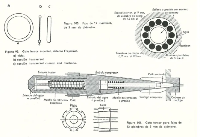
(7) suppose, it would be possible to wonder whether the different systems of pre-stressing execution provide substantial differences to the form of the objects they are applied to, or whether they actually are the result of the industrial and economical circumstances and the means available for construction in each country. In general, there are two different ways to stress the reinforced concrete framework: the first one consists in applying the tension before concrete is poured (pre-stressed concrete with prestressed framework); in the second option the effort is applied once that the concrete has hardened (pre-stressed concrete with post-stressed framework). The first system is used, in a preferable way, in prefabricated structures since it requires spacious and permanent installations to build parts economically. Therefore, it is complicated to execute them in building works. In this case, frameworks are previously stressed between supports and then concrete is poured. One it has hardened, the anchorage is released and the framework tends to adopt its original state, which generates compression tensions in the concrete. This group includes Wettstein plates system (Czechoslovakia), which originally dates back to 1919, construction elements and Gloeser pre-stressed concrete posts (Czechoslovakia) and even some beams according to Freyssinet system (France), places with one or more empty layers according to Schaefer system (Germany), pumice stone concrete and gravel concrete with pre-stressed framework combined Remy plates (Germany), Hoyer piano wire reinforced concrete (Germany), to the tendency for the diameter of the steel to increase slightly at the ends when it is released. In the second system (pre-stressed post-stressed concrete) two new types are distinguished depending on the way that tendons stressing is executed and on its adherence to concrete. In the first type no adherence exists between tendons and concrete, thus it is possible to even place these tendons out of the concrete mass and anchor it in the ends of the parts. This kind of prestressing may allow the introduction of new tensions along the lifespan of the structure. Opposite to the first one, in the second type of pre-stressed post-stressed concrete, the aim is achieving final adherence to concrete; this is the most common procedure when works are executed in situ. In the case of pre-stressed concrete with post-stressed tendons without adherence to concrete, tendons can be previously stressed, when they are located in the concrete mass. Between the years 1925 and 1928, several inventors worked independently on this idea. We can mention, for instance, Dill (United States); in his work, steel bars were submerged into liquid asphalt before. Figure 5. Anchorage and Jack of Freyssinet system. CRUZICS-Fullpaper[0542-1190].indd 917. 5/29/2013 7:31:24 AM.
(8) being stressed. In Germany, Faerber applied, in 1927, for a patent for a procedure that might be used in the fabrication of reinforced concrete beams avoiding this previous adherence by coating the framework, stressing and finally anchoring by screwing. Nevertheless, it was Freyssinet who achieved a significant advance in this system with a patent that was obtained shortly after Dill’s one. He used steel with the right resistance and subjected it to high tensions producing a pre-stressing effect that did not disappear over time. Before their stressing, tendons may also be located out of the concrete mass; this is what happened with some triangular trusses built in France between 1925 and 1926 for aircraft hangars with 55m span, in which all their elements were subjected only to tension stress. Dischinger (Germany) patented a procedure to build reinforced concrete arched bridges, with hanging board and with reinforced concrete ties where the additional loads produced in the arch due to the tie dilation are avoided by pre-stressting that arch. In 1936 he also proved that thanks to prestressing it was possible build reinforced concrete beam-shaped bridges with 150m span; the biggest bridge built up to that point, in 1934, was 70m span. Belgian Carlos Wets proposed as well some new options for building beams with pre-stressed tendons out of the concrete mass. Pre-stressed concrete with post-stressed tendons with adherence to concrete systems are the most commonly used in those elements that are produced in situ and it is probably the richest field as regards steels in use, cross section shapes, tendons positioning and tensioning devices and anchorage organization. In this system, the tendons are located in ducts like channels that are left empty in the concrete mass. After its hardening, the tendons are introduced (in case it was not placed yet) and stressed. Finally, steel and concrete are united by filling with mortar or cement paste the empty spaces between them. The anchorage is basically mechanical, since steel used for pre-stressing cannot be welded. There are five general types of anchoring: wedge or hook anchors, rivet anchors, threaded anchors with nuts and slabs, anchors in the concrete by forming ties in the framework and anchors by adherence and friction with the concrete. Wedge or hook anchors are one of the most frequently used systems. It consists in making that the tightened wires that form the tendon go through a cylindrical or truncated cone-shaped hole to support it by the introduction of a truncated cone-shaped wedge and, in most cases, with little projections embedded in the wires. The wedge may be formed by two parts that encircle the wire like in Stronghold system, CTT or VSL that now all they are in the same business group, with constructions like the new Miño bridge in Ourense, and CCL, system used in the old Barajas Airoport. Or also, the wedge may be formed by a single part, like the one in Freyssinet’s patent; this patent has been recently used to build the Telekom Malaysia Tower in Kuala Lumpur or the National Bank Tower in Abu Dhabi (developed in France), whose German patent was bought by Wayss & Freytag AG. In Belgium, the following procedures have been developed using this system: Magnel-Blaton system, it was used in the first pre-stressed concrete bridge that was built in Philadelphia, USA, in 1949; and the Franki-Smet procedure. In Italy, Morandi (who had also developed his own system) reached the conclusion that wedge anchors were the most simple and the most effective ones. Morandi designed many works with this system like the General Rafael Urdaneta Bridge, crossing of Lake Maracaibo o the Vespucci Bridge in Florence. In Switzerland, the VSL (Vorspann System Losinger) system was created, and patented in 1954-55. In Spain, the Barredo system was developed and it is very often linked to very representative architecture works such as M. Fisac’s ones. The second type of anchoring, rivet anchors, is the typical one in BBR swiss system; it consists in making the wires pass in parallel through a perforated disc. The ends of the wires are cold-hammered with a portable machine, creating a rivet head superior to the disc perforations. This option excludes the possibility of slipping but it requires a high level of precision when cutting the wires since the rivets must be placed on the same plane. In the United States, the Prestressed Concrete Corp (from Kansas city) developed a framework very similar to the BBR one, denominated Strescon. The main problem in this country was specialized workforce price, which made other technologies more affordable than prestressed concrete. This system was used in the construction of works such as San Roque González de la Santa Cruz Bridge which joins Argentina and Paraguay crossing Paraná river. The third anchorage system is utilized in the screw-and-nut mechanism. In Germany, the Dywidag system was developed; this system uses not high yield strength steel. There are other. CRUZICS-Fullpaper[0542-1190].indd 918. 5/29/2013 7:31:25 AM.
(9) systems like MacAlloy Bars or Lee-McCall system (England). Anchorage is very simple but, due to its thick diameter, bars cannot achieve the complex mechanical features of wires. It is principally used in shorter pre-stressing procedures, like transversal pre-stressing with lengths inferior to 4m. The fourth prestressed poststressed concrete anchorage type is obtained as the result of looping the wires in the concrete frameworks. Following this system, several procedures have been developed in Germany: Baur-Leonherdt system, or stressing procedure Kani-Horvat, which allows building prestressed concrete beams composed of two parts which may be placed either one inside the other, or one beside the other with slipping. In the USSR, Korowkin procedure was utilized; in it, wires were placed concentrically in different layers around a core bar. Finally, the last type is framework wires anchorage by adherence and friction with the concrete. This system was used in Germany to create the following mechanisms: Beton & Monierbau AG stressing procedure; in it, the wires are put together in bundles and placed in rectangular cross-sectional metal duct; to stress the wires, they are anchored in a steel cone filled with concrete. Another mechanism is Gruen & Bilfinger AG stressing procedure. In these systems it is necessary to fabricate very carefully the anchorage block, which means that concrete must be introduced among the numerous threads without altering concrete dosage and without leaving empty spaces. Slip resistance is essentially influenced by curvature friction. There is another system denominated Figueiredo Ferraz (Brasil) and it is closely related to São Paolo School architecture works, such as São Paolo Art Museum, in Brasil. As a conclusion, wedge anchors appear to be, in practice, the most appropriate ones to stress tendons longer than 50m.Theoretical inconveniences such as a sporadic wire slip are not frequent and could also be compensated. On the other side, rivet head and screw-and-nut anchors offer greater advantages when tendons are shorter than 4m, and straight in the case of threaded bars. Builders have also a certain tendency to keep the possibility of delaying tendons threading until the most favourable moment, since this supposes beneficial flexibility in work organization. Furthermore, the problems caused by an accidental introduction of mortar in the sleeves during the concreting process are serious if the framework had been previously placed and mild if the wires have not been threaded in the conduits. Thus, mastery of form and its geometry by controlling the strains provided by the prestressing technique, frees the designer of choice a priori structural type of buildings. The building manages to be an object with its own laws of integrity and coherence, resulting in a singular form, not as a result of formalism or display but of the need created at the origin. (García del Monte JM. 2006). Prestressing systems offer as a result of this new freedom, a way to see how technology can define architectural forms. The existing constructive typologies as a result of the structural needs tend to be diluted as form and geometry turn out to be a spatial and technological imposition. REFERENCES Aguiló Alonso, Miguel. Ingeniería Versus Obras Públicas en el periodo de entreguerras. Revista de Obras Públicas. Junio 2003. Pag 73 a 82 Almagor, Shlomi, Análisis Estético-Histórico de El museo Kimbell en Texas de Louis I. Kahn. pag. 145170 Arquitectura: proyecto y uso. 2003. Josep Muntañola Thornberg Anaya Díaz, Jesús. 2011. Geometría, Estructura y Forma. Centro George Pompidou. Jornadas internacionales de investigación en construcción. Hitos Estructurales de la Arquitectura y la Ingeniería. Instituto de Ciencias de la Construcción "Eduardo Torroja". CSIC Fernández Ordoñez, José Antonio. Eugene Freyssinet. Abril 1978. Revista del Colegio de Ingenieros de Caminos Canales y Puertos. Pag 267 a 275 García del Monte, José María. 2006. De las posibilidades arquitectónicas del pretensado. Técnica y Proyecto en la obra de Paulo Mendes Da Rocha. Tesis Doctoral. ETSAM Lozano-Galant, J.A y Payá-Zaforteza, I. La cubierta del Frontón de Recoletos al desnudo. Jornadas internacionales de investigación en construcción. Hitos Estructurales de la Arquitectura y la Ingeniería. CSIC Páez, Alfredo. 1989 El hormigón Pretensado en ingeniería y en arquitectura. Bellisco Editorial. Torroja Miret, Eduardo 2000 Razón y ser de los tipos estructurales. Consejo Superior de Investigaciones Científicas. CRUZICS-Fullpaper[0542-1190].indd 919. 5/29/2013 7:31:25 AM.
(10)
Figure


+2
Documento similar
- Contextualize your action. Civic learning is part of the practice of the.. same, with which any established educative proposal should have in mind the concrete reality in which
In most cases, simplified assumptions made in the preliminary considerations (pre- emptive yielding of steel, concrete and steel failure in unconfined and confined
The next steps in this research line may be (1) to analyze the use of coarse RA in a precast-concrete plant considering, in addition to the aspects covered in this paper,
The concrete syntax part works in the same way as in the pure meta-modelling approach, but we define (non-monotonic) triple graph grammar rules [11] to build the abstract syntax
Before offering the results of the analysis, it is necessary to settle the framework in which they are rooted. Considering that there are different and
Stable isotopes applied to the study of the concrete/bentonite interaction in the FEBEX in situ test
S patial distribution of δ 13 C values along the concrete plug and the first centimeters of the bentonite barrier points to the existence of a diffusion front of carbon species from
In such cases, the designer can still use a concrete syntax pattern to automate the generation of a modelling environment, for which he needs to map meta-model elements to
The formation of Mg silicate phases in the bentonite barrier near the concrete may have 417. some consequences in terms of
