Application of the beam method to structural calculation of the long cylindrical concrete shells in the work of Felix Candela
11
0
0
Texto completo
(2) Figure 1. Long cylindrical shells on the roof, under construction, in the Dywidaghalle. (Dischinger & Finsterwalder, 1926).. The theory of elasticity began to be implemented in the structural calculation of long cylindrical shells in Germany in the 1930s, as a result of the work by the engineers U. Finsterwalder (Finsterwalder, 1928, 1932, 1936) and Fr. Dischinger (Dischinger, 1926, 1928, 1930, 1935, 1936), and later by the Norwegian A. Aas Jakobsen (Jakobsen, 1937, 1939, 1940, 1941). The mathematical formulation provided by analytical theory, which was at that time widely used and referred too ideal, homogeneous and isotropic materials complying with Hooke's law, was also applied to the structural calculation of long cylindrical reinforced concrete shells, without any consideration being given to the characteristics of the new construction material used. However, it was practically impossible to apply the elastic theory of shells, as it involved solving complex eighthorder differential equations, based on unreal hypotheses about the surrounding conditions and the structural material used. All these hypotheses involved either idealising a reality that was impossible to ascertain a priori, or referred to an ideal, homogeneous and isotopic material, when reinforced concrete does not have any of those properties. It was always impossible to guarantee that the state of stress obtained in the shell represented the indisputable "real state" of the structure. Consequently, some obvious and significant insurmountable inconsistencies between the results obtained from the elastic calculation and the results under real conditions and in tests began to appear. This was all due to shortcomings of manufacturing and execution, and above all, small geometric variations in the structure, which were basically unknowable and impossible to anticipate in the calculation. In this context, in 1944 the Danish engineer Knud Winstrup Johansen published a very important article in which he carried out a structural analysis of a long cylindrical shell in a real roof (Johansen, 1944). The calculation was based solely on the equilibrium equations approach, thereby enabling a simple and reliable calculation of these structural types. Other engineers such as the Hungarian G. Kazinczy (Kazinczy, 1949) and the Dane H. Lundgren (1949) subsequently continued with this type of study; it was the latter, as well as K.W. Johansen who formulated a practical, clear and simple theory for application based on the equilibrium approach in the late 1940s. From 1950 onwards, until the appearance of computer technology, the structural analysis of long cylindrical roof shells involved either performing the relevant calculations based on elastic theory, and as such accepting the need to solve complex mathematical calculations based on unreal hypotheses, or on the other hand, applying methods based on the stress balance approach, thereby facilitating a simple and reliable calculation based on the balance approach. The latter method was used by some engineers and architects to calculate these structural types; these included the architect Félix Candela Outeriño. Despite the fact that a great deal has been written about the application and development of elastic calculation in the specific case of long cylindrical reinforced concrete roof shells, this study will attempt to fill a void in the existing knowledge concerning these structural types. This void is in the application of calculation methods based on the approach using stress equilibrium equations, which enabled architects like Félix Candela to construct these types of buildings safely.. 135.
(3) For this reason, the objective is to perform the calculation of a real long cylindrical shell, chosen from among the works executed by Felix Candela, based exclusively on stress balance approaches as discussed below.. State of the art Félix Candela's influence on the relationship between geometry and structural analysis A great deal has been written about the life and work of the architect Félix Candela Outeriño (1910-1997); however, there has been very little examination of the impact of this knowledge on how geometry was used in the calculation of his structures. Laminar reinforced concrete structures, which had been built in Europe since the 1920s, had attracted the attention of the young Candela during his studies for his degree. However, it was not until 1945, six years after his arrival in Mexico, when Candela concentrated on their study and structural analysis (Candela 1951, 1955, 1958, 1963). It was at this point that as part of his quest to find new calculation methods that were simpler than those provided by the application of elastic theory, Candela became interested in reading other texts, as well as the German texts (Faber, 1963). The obsessive introduction of elastic methods in all structural systems was also not shared by some prestigious engineers, such as K.W. Johansen (Johansen, 1944, 1948), H. Lundgren (Lundgren, 1946, 1949) or even G.v. Kazinczy (Kazinczy, 1946, 1949), whose work and research could by no means be dismissed as superficial. Thanks to these texts, Candela gave in-depth consideration to the assumption that reinforced concrete shells could be analysed by applying simpler methods, based on the different states of equilibrium that the structure can adopt, depending on its geometry and the application of loads, i.e. based on the structure's approach to balance (Candela, 1951). Prior to the publication of the book Cylindrical Shells by H. Lundgren in 1949 (Lundgren 1949), the literature about the structural analysis of long cylindrical shells contained very few studies of the problem, apart from membrane theory (Emperger, 1910; Reissner, 1908), and above all the theory of elasticity. However, there were various avenues towards the simplification of analytical tools for shell design, such as those proposed by the engineers W. Flügge (Flügge, 1934), R. Vallette (Vallette, 1934), H. Schorer (Schorer, 1935), U. Finsterwalder (Finsterwalder, 1936), and the Danish engineer A. Aas Jakobsen (Jakobsen, 1940). In 1951, Felix Candela presented an essay at the II Mexican Scientific Congress, in which he definitively disassociated himself from conventional methods for structural calculation, based on the theory of elasticity (Candela, 1951). He began to consider the behaviour of structures in general, and of shells in particular, in a similar way to a transfer of stresses from the parts of the structure that are under most strain to those that are under least strain, which all depends on the transversal geometry of the shell. The question is therefore one of adjustment or of balance between stresses and strains, in which different states of balance can exist; any of them are valid, even if they are obtained using a complex and tedious method such as the theory of elasticity. The validity of the results obtained using the theory of elasticity is guaranteed to the extent that the assumptions used prior to the calculation are accurate. In other words, there should be no objection to the elastic calculation procedure, as long as the structural materials used comply with the conditions of the basic elasticity hypothesis; however, this was not the case with reinforced concrete cylindrical shells. Without intending to distort the application of the elastic theory, the present work tries to fill a knowledge gap in relation to the use of other simpler calculation methods on these structural typologies, specifically the socalled beam method. This method, based on the study of different equilibrium states, allowed Félix Candela to carry out a structural analysis of these typologies in 1951 in a clear, simple and safe way, as it will try to demonstrate. In the absence of a single solution to the problem, the structure reacts against the action of all possible loads that appear, or the possible shortcomings in their foundations, if there are any. The structure will adopt the more appropriate solution involving a distribution of stresses and strains, enabling it to continue to comfortably withstand the external forces which it is subject to in each case. Any state of the structure in which the equilibrium of forces occurs can be studied, meaning that the calculating engineer could focus on studying the safety of the shell in each one (Candela, 1963; Faber, Echegaray & Candela, 1970).. 136.
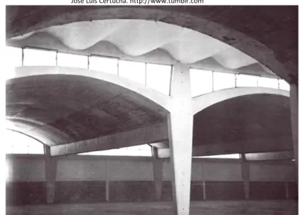
(4) From a universal point of view, the determining factor in the choice of a structural form or geometry is the real state of the analytical technique that must be used in the preliminary investigation or analysis of the structure. For this reason, Candela decided that analysing and executing these geometries would determine whether what had previously been written about them was true or not. Candela used this method to calculate and execute his reinforced concrete shells (Candela, 1963, 1970; Garlock & Billington, 2008). From 1950, Candela uses the method of the beam, and no other to perform the structural calculation of long cylindrical shells, considering it a method based on the hypothesis that the shell works as if a beam straight, hollow and circular cross section was. Therefore, the shell is calculated longitudinally and transversally, as a whole, as if it were a beam. Candela considers that of the geometric analysis of the transverse and longitudinal sections of long cylindrical shells for roofs can obtain different states of equilibrium, in order to enable a simple and accurate calculation of the structure (Faber, 1963). The various states of equilibrium obtained in the shell are obtained depending on the transverse geometry of the shell, the location of the neutral fibre and the various arrangements chosen for the reinforcement, as shown below, it will be demonstrated. The state of equilibrium obtained from purely geometrical considerations is therefore a solution to the problem, but not the only one. Still, Candela writes about the need of checking the safety of the shells against buckling (Candela, 1951) by employing the empirical formulas by H. Lundgren (Lundgren, 1949).. Methodology In 1951, Félix Candela constructed his first long cylindrical shell for the roof of the Pisa Warehouse, in San Bartolo, in the State of Mexico (Figure 2). Edge beams and joints between contiguous units appear in the shells that make up the structure of this building. Candela himself justified the use of these elements, arguing that at that time he was unaware of the advantages of continuity in cylindrical shells made of reinforced concrete. This structure also contained one of Candela's first sinusoidal flagstones (the first was the one constructed in the cantilever roof of Boliches Marsella, in Mexico City in 1950); this type of sheet is based on the same principles as the long cylindrical shell, but the transverse bending moments are practically negligible due to its size. Figure 2. Interior view of the Pisa Warehouse, San Bartolo, State of Mexico, Mexico 1951. Félix Candela and José Luís Certucha. http://www.tumblr.com. The theory formulated by K.W. Johansen and subsequently developed by H. Lundgren (Johansen, 1944; Lundgren, 1949) was studied and applied by Félix Candela in his structural analysis of long cylindrical roof shells. Years later, J. A. Tonda Magallón, a follower and collaborator of Candela, would disseminate this theory in Spanish with the publication of his book in 1973 (Tonda, 1973). 137.
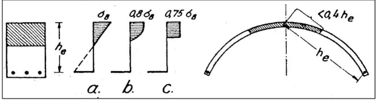
(5) The structural analysis method used is based on the long cylindrical shell's similar behaviour to that of a reinforced concrete beam (Figure 3), which has the following calculation process: Figure 3. Diagram of similarity between a reinforced concrete beam and a long cylindrical shell (Faber, Echegaray, & Candela, 1970).. Results Longitudinal calculation of the shell First, it is necessary to obtain the value of the permanent and variable external forces acting on the shell. After measuring the angle in radians, the angle forming the base of the shell with the horizontal, and incorporating the geometry of the cylindrical shell to that of a beam, the total bending moment is given by the expression (Lundgren, 1949): 1. 𝑀𝑍 = 𝑞𝑧 𝑙 2. 1. 8. where l represents the span of the shell and 𝑞𝑧 is the vertical resulting from the load per unit of length on the axial axis x. When the shell is considered a beam throughout the entire calculation process, and is only subject to bending on its vertical plane. The stresses in direction x, 𝜎𝑥 , are given by the same expression as for the simple bending of a beam (Lundgren, 1949): 𝜎𝑥 =. 𝑀𝑧 𝑧, 𝐼𝑧𝑧. where 𝑀𝑧 is the bending moment due to the load 𝑞𝑧 , 𝐼𝑧𝑧 is the moment of inertia of the transverse section of the beam, for the neutral line and the centre of gravity G and Z is the specific distance from the point to the neutral fibre of the cross section of the shell. The value of this bending moment is resisted by the internal stresses; as such, it is necessary to calculate the magnitude of the stresses in order to determine the amount of reinforcement required in the shell. The values of these stresses depend in turn on the lever arm, the distance between the centre of compressions and stresses, which is determined by means of extremely simple expressions derived from the geometry of the shell to be studied itself (Figure 4). The resultant amount for the axial stress, Nx, for each 10 cm of the width of the edge beams, as well as the necessary reinforcement area within them are given by the expressions (Lundgren, 1949): 𝑁𝑥 =. 𝑀𝑧. 𝑆 (𝑆 ), 𝐼𝑧𝑧 𝑧 0. 𝐴=. 𝑁𝑥 𝜎. 2. The resultant amount for the tractions is located in the centre of masses in the steel reinforcement area. Meanwhile, the resultant amount for the compressive forces would be located at a distance of 1/5, where the distance between the crown or upper point of the shell and the centre of gravity of the shell is determined (Figure 4).. 138.
(6) Figure 4. Obtaining the neutral axis of the state of equilibrium in the cross-section of the long cylindrical shell projected by F. Candela for the Pisa Warehouse, San Bartolo, State of Mexico. Source: self-elaboration according to data collect (Faber, Echegaray &Candela, 1970).. The calculation of the theoretical distance of the lever arm in the shell and the location of the centre of stresses would thus be determined immediately by (Lundgren, 1949): 𝑍=. 𝐼𝑧𝑧 2𝑆𝑧 (𝑆0 ). 3. The state of equilibrium in the shell is therefore achieved by transferring the stress from the areas under most strain to the areas under least strain; this all depends on the transverse gometry of the shell, the location of the neutral axis or lever arm, and the various provisions made for the reinforcement. The lever arm is obtained by selecting a neutral line in the cross-section of the shell, and the internal stresses are counteracted with the moments due to loads. As shown above, the area for reinforcement required for this particular state of equilibrium is obtained by basic arithmetic. The state of equilibrium thereby obtained is one solution to the problem, but not the only one. On this basis, and given a cross-sectional geometry, it is possible to study any state of the structure in which equilibrium between the acting forces occurs. Transverse calculation of the shell Similarly, based exclusively on considerations purely of geometry and balance, the shear stresses and their location in the cross-section of the shell can also be calculated. The maximum value of the tangential stress will be determined by Lundgren (1949): 𝑁𝜑𝑥 =. 𝑄𝑧 𝑆 (𝑆 ) 𝐼𝑧𝑧 𝑧 0. 4. As a result, the reinforcement area necessary would also be obtained immediately. After calculating the maximum values of the normal stress in the direction of the shell, Nx, and of the tangential stress, Nx, it is possible to obtain the value of the normal stress in the direction tangential to the curve, N, the bending moment in the direction tangential to the curve, M (transverse moments) and finally, the shear stress in the direction tangential to the curve, Q.. 139.
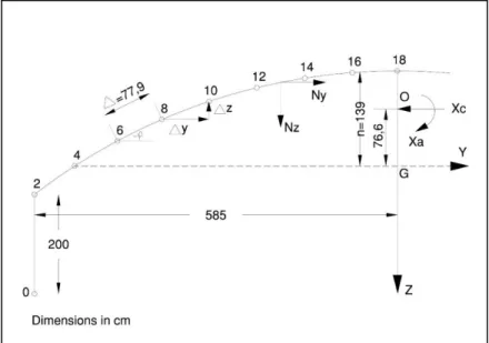
(7) To that end, two cross-sections are selected in the long cylindrical shell, which are separated from each other by a very small distance, dx=1. On this basis, it is possible to calculate the transverse moments considering the balance in this transverse strip. If the arc constituting the cross-section of the shell is divided into two halves, and each half is divided into eight parts (Figure 5), an area of with a concentrated range can be assumed to be in the centre of each one. This provides successive tangential stresses, with each one belonging to each range, instead of a single stress in the cross-section of the shell. Figure 5. Analytical justification for the transversal calculation of the long cylindrical shell of the Pisa Warehouse, San Bartolo, State of Mexico, 1951. Source: self-elaboration according to data collect (Lundgren, 1949). According to this division, the first interval, 0-2, would be for the location of the edge beam, on the edge of the shell, with an area considered uniformly distributed throughout its height of 2 m. With all these data, as well as those for the geometry of the section (Figure 5), the data shown in the following table can be obtained: Table 1. List of variables for calculation of transverse moments in the long cylindrical shell of the Pisa Warehouse, San Bartolo, State of Mexico. Félix Candela 1951. Source: self-elaboration according to data collect (Faber, Echegaray &Candela, 1970). 𝑆𝑧⁄ 𝜕∆ (𝑚) 0.00. q (Kg/m). 𝑁′𝑥𝜑 (Kg/m2 ) 0. ∆𝑌 (m) 0.00. ∆𝑍 (m) -1.00. 𝑁′𝑥𝜑 ∆𝑌 (Kg/m). 𝑁′𝑥𝜑 ∆𝑍 (Kg/m). 𝑞𝑧 (Kg/m). Y(m) -5.85 -5.85. Z(m) 2.45 1.45. 𝑍2 (𝑚2 ) 10.36. 2. -5.85. -5.53. 0.45. 0.24. 0.06. 6.17. 1325. 995. 0.32. -1.21. 318. -1431. -106. 4. -5.20. -4.86. 0.03. -0.16. 0.03. 6.41. 200. 1033. 0.67. -0.40. 693. -413. -213. 6. -4.51. -4.16. -0.34. -0.50. 0.25. 6.25. 200. 1007. 0.70. -0.34. 705. -343. -143. 8. -3.80. -3.44. -0.66. -0.80. 0.64. 5.75. 200. 927. 0.72. -0.30. 667. -278. -78. 10. -3.07. -2.69. -0.92. -1.03. 1.06. 4.95. 200. 798. 0.75. -0.23. 599. -183. 17. 12. -2.32. -1.93. -1.13. -1.21. 1.46. 3.92. 200. 632. 0.76. -0.18. 480. -114. 86. 14. -1.55. -1.17. -1.27. -1.33. 1.77. 2.71. 200. 437. 0.76. -0.12. 332. -52. 148. 16. -0.78. -0.39. -1.36. -1.38. 1.90. 1.38. 200. 222. 0.78. -0.05. 173. -11. 189. 18. 0.00. 0. 100. 0. 0.39. -0.01. 0. 0. 100. 37.54. 2825. 6051. 5.85. -3.84. 3967. -2825. 0. Points 0. -1.39 17.53. 140.
(8) where: ∆𝑦 = 𝑐𝑜𝑠𝜑∆, ∆𝑧 = 𝑠𝑒𝑛𝜑∆ The first column shows the various intervals in which the arc that forms the cross-section of the shell has been divided (0, 2, 4, …, 18). The second column represents the distances, according to the axial axis y, from the initial or intermediate point of each interval of the arc to the point G, or the centre of gravity of the shell (Figure 5). This second column is divided in two. The first refers to the distances from the initial points in each interval, while the second is the distances from the intermediate points; as mentioned above, they all relate to point G. The third column shows the same as the second, but in this case the distances are measured according to the axial axis z. The fourth column shows the values for 𝑧 2 , the value necessary to resolve Izz, the value of the point of inertia for the neutral line and the centre of gravity of the cross-section of the shell, using the following expression (Lundgren, 1949): 𝐼𝑧𝑧 = 2𝑧 2 ∙ 𝛿∆,. 5. The static moments, such as the area of each interval of the arc, , are considered to be concentrated at the mid-point of the interval, (3, 5, 7, …, 17), the value of the static moment is considered constant within the same interval and concentrated at its midpoint. Similarly, the load q is considered to be uniformly distributed in each interval. The value of the tangential forces in each interval of the arc, N’x, is obtained by the expression 2 with the data obtained in the previous columns; and their vertical and horizontal components. Having obtained the components of the tangential forces, (𝑁′𝑥𝜑 ) 𝑦 and (𝑁′𝑥𝜑 ) 𝑧 , which arise at each point, adding all of them together interval to interval gives the values for the horizontal and vertical components of the internal forces Ny and Nz, applied at the intermediate points of each range, as shown in the two first columns of Table 2. Table 2. Calculation of the transverse moments in the long cylindrical shell in the Pisa Warehouse, San Bartolo, State of Mexico. Félix Candela 1951. Table by the author.. Ny (Kg/m). Nz (Kg/m). Z (m). Y (m). 𝑁𝑦 ∆𝑍 (𝐾𝑔). 𝑁𝑧 ∆𝑌 (𝐾𝑔). ∆𝑀𝜑 (Kg). 𝑀𝜑 , 𝑂 (Kg). 𝑍1 (m). 𝑍12. −𝑍1𝑀𝜑, 0 (Kgm). 𝑀 (Kg). 2. 0. 0. -2. 0. 0. 0. 0. 0. 1.215. 1.476. 0. -248. 4. 318. -106. -0.42. 0.65. -134. 69. -65. -65. 0.795. 0.632. 52. -6. 6. 1011. -319. -0.37. 0.69. -374. 220. -154. -219. 0.425. 0.181. 93. 110. 8. 1716. -462. -0.32. 0.71. -549. 328. -221. -440. 0.105. 0.011. 46. 122. 10. 2383. -540. -0.26. 0.73. -620. 394. -226. -666. -0.155. 0.024. -103. 86. 12. 2982. -523. -0.21. 0.75. -626. 392. -234. -900. -0.365. 0.133. -328. 5. 14. 3462. -437. -0.14. 0.77. -485. 337. -148. -1048. -0.505. 0.255. -529. -41. 16. 3794. -289. -0.09. 0.77. -341. 22. -119. -1167. -0.595. 0.354. -695. -94. 18. 3967. -100. -0.03. 0.78. -119. 78. -41. -1208. -0.625. 0.391. -755. -113. -3.84. 5.85. -3248. 2040. -1208. -5109. 0.0. 0.524. -1842. 1. Points. 0. 141.
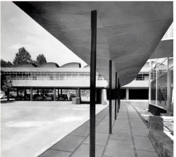
(9) As can be seen in the results obtained, the maximum compressive force is applied at the highest point of the shell, point 18 (Figure 5). The bending moments caused by internal forces, Ny and Nz, and their increases in each interval are easily found by determining the different lever arms for each interval, z and y. As a result, the increase in the value of the transverse moment in each interval will be defined by the expression (Lundgren, 1949): ∆𝑀𝜑 = 𝑁𝑦 ∆𝑧 − 𝑁𝑧 ∆𝑦. 6 The total of the various increases, M, can be used to obtain the value of the transverse moments in each interval, starting from a null value at the beginning. The values for the initial moments due to the horizontal thrust that is unknown in point 2 should be added to these values. These moments can be obtained in the same way as in the case of a fixed arc; i.e. by determining the values of the reactions. The value of the total transverse moments will therefore be the value for the result of the operation (Lundgren, 1949): 𝑀𝜑 = 𝑀𝜑,0 − 𝑋𝑎 + 𝑍1 𝑋𝑐 ,. 7. these values appear in the final column of Table 2, where Xc is the value of the horizontal stress. In short, in the crown of the shell there would be a value for the normal force in the direction tangential to the curve, N, of Lundgren (1949): 𝑁𝜑 = 𝑁𝑦 + 𝑋𝑐. 8. As a result of all the above, the calculation of the necessary reinforcement is immediate. In short, both the shear forces and the corresponding necessary reinforcement are calculated in the same way as in a concrete beam. The transverse moments due to tangential stresses are obtained by statics, considering the balance in a transverse strip of uniform length subject to the vertical loads acting on it; and the difference between the shear forces in both cross-sections that border the strip. This difference is considered to be unitary forces tangential to the cross-section. Félix Candela subsequently began work on the construction of new CIBA Laboratories in 1953. In this project, in which financial considerations were not an issue, he projected long cylindrical saw-tooth cylinders on the laboratory areas (Figure 6). Figure 6. Interior view of the courtyard between production and storage in the CIBA Laboratories, Churubusco, Mexico 1954. Alejandro Prieto, assistant architect: Enrique Manzanares and technical assistant: Félix Candela. http://www.tumblr.com. 142.
(10) In the roof of this building, long cylindrical saw tooth shells have a lever arm with very small internal forces, in comparison with the total overhang, to counteract longitudinal bending. This requires more reinforcement, and diagonal bars near the supports to absorb shear forces greater than those in a normal long cylindrical shell. Meanwhile, the free horizontal upper edge cannot be left unsupported because it would buckle; it must be supported by columns with a small cross-section supported on the lower edge beam of the adjacent shell, with the increase in reinforcement that this entails. In his analysis, Candela again used the beam method mentioned in the published texts mentioned above, by the engineers K.W. Johansen, H. Lundgren and G. Kazinczy (Johansen, 1949; Lundgren, 1949; Kazinczy, 1949) In this case, the method consists of first finding the centre of inertia in the cross-section of the saw-shaped shell and its main axes. The bending experienced by the shell's cross-section is subsequently calculated using the same procedure as outlined above. Once again, the centre of inertia of the cross-section can be found using equilibrium systems as outlined above. In 1967, with Max Cetto, Candela executed the Tenería Temola building in Morelos, Mexico; used for leather footwear. The method used by Felix Candela to calculate the long cylindrical shells for the roofs of these buildings is therefore based on choosing the correct state of equilibria between the forces and moments acting on the chosen transverse section, which the structure adopts at some intermediate stage before it collapses. In other words, Candela analyses different certain states of equilibrium which are therefore valid obtained from the geometry of the structure.. Conclusions Felix Candela compared the behaviour of long cylindrical shell shells to that of a hollow reinforced concrete beam in order to be able to use a simple and safe calculation method, based on the balance of stresses. The beam method provides an equilibrium solution which is a safe solution in cases where the shell is made of a ductile material, and in the absence of instability problems; without taking into consideration the surrounding conditions in these types of structure, which are variable and impossible to determine. The state of equilibrium in the long cylindrical shell is achieved by transferring stresses from the areas most subjected to them to those that are least. This all depends on the transverse geometry of the shell, the location of the neutral axis and the various provisions made for the reinforcement. The state of equilibrium thereby obtained is therefore one solution to the problem, but not the only one. As a consequence of the above, one of the primary objectives of Félix Candela was to obtain conditions geometrically in cylindrical shells, and the most appropriate ratios on their edges for the purposes of calculation. Unlike the advocates of the unique and exact solution as set out in the Theory of Elasticity, Candela considered the structural conception in relation to the natural processes of thought that man had created in order to understand and relate to the world around him; or in other words, as he said himself, "What we need is a structure, not an analysis.". References Candela, F. (1951). Hacia una nueva filosofía de las estructuras. II Congreso Científico Mexicano. Revista Ingeniería, Vol. XXV, No. 2, México. Candela, F. (1951). Simple Concrete Shell Structures. Journal of the American Concrete Institute, (48), 321-333. Candela, F. (1955). Structural Applications of Hyperbolic Paroboloidical Shell. Journal of the American Concrete Institute, (51), 397-419. Candela, F. (1958). Understanding the Hyperbolic Paraboloid. Architectural Record, 123(7), 191-195. Candela, F. (1963). Arquitectura y Estructuralismo. Arquitectura, 59. Dischinger, Fr & U. Finsterwalder U. (1926). Die Dywidag-Halle auf der Gesolei. Der Bauingenieur 7, pp. 929, 930. Dischinger, Fr. & Finsterwalder, U. (1928). Eisenbetonschalendächer System Zeiss-Dywidag. Der Bauingenieur, 9(44), 807-812.. 143.
(11) Dischinger, Fr. (1928). Schalen und Rippenkuppeln, 4a ed. Handbuch der Eisenbetonbau. VI Band, Zweiter Teil.. F. von Emperger (ed.). Berlín: Verlag von Wilhelm Ernst und Sohn, 163-383. Dischinger, Fr. (1930). The Zeiss-Dywidag system of construction for reinforced concrete shell roofs over large spans. First International Congress for Concrete and Reinforced Concrete, Liège. Dischinger, Fr. (1935). Die strenge Theorie der Kreiszylinderschale in ihrer Anwendung auf die Zeiss-Dywidag-Schalen. Beton u. Eisen, (34), 257-264, 283-294. Dischinger, F. (1936). Shell Construction in Reinforced Concrete. Second Congress IABSE, Berlin, preliminary Report, 2, 693-706. Emperger, F. v. (1910). Handbuch für Eisenbetonbau: FlüssigkeitsbehalterRöhren, Kanäle. W. Ernst. Faber, C. (1963). Candela, the shell builder. Reinhold Publishing Corporation. Faber, C., Echegaray, M.M. & Candela, F. (1970). Las estructuras de Candela. Compañía Editorial Continental, S.A. Mexico-Spain-ArgentinaChile. Finsterwalder, U. (1932). Die Theorie der kreiszylindrischen Schalengewölbe System Zeiss-Dywidag und ihre anwendung auf die Grossmarkthalle in Budapest. Journal of Bridge and Structural Engineering. First Congress IABSE, Paris, 127-152. Finsterwalder, U. (1936). Cylindrical shell structures. Second Congress IABSE, Berlin, Rapport Final, 2, 449-453. Flügge, W. (1934). Statik und Dynamik der Schalen. Berlin: Verlag von Julius Springer. Garlock, M. E. M., & Billington, D. P. (2008). Félix Candela: engineer, builder, structural artist. Princeton University Art Museum. Gvozdev, A.A. (1936). Opredelenie velichiny razrushayushchei nagruzki dlya statischeski neopredelimykh sister, preterpevayushchikh plasticheskie deformatsii. Proceedings of the Conference on Plastic Deformations, Akademia Nauk SSSR, Moscow-Leningrad 1193, 1930. Translation to English: The determination of the value of the collapse load for statically indeterminate systems undergoing plastic deformation. International Journal of Mechanical Sciences, 1, 1960, 322-335. Jakobsen, A. Aas. (1937). Sur le calcul de la voûte cylindrique circulaire. Travaux (60), 529-535. Jakobsen, A. Aas. (1937). Les voiles cylindriques de forme elliptique. Le Genie Civil, vol. CXI (16), 323-326. Jakobsen, A. Aas. (1939). Über das Randstörungsproblem an Kreiszylinderschalen. Der Bauingenieur (29), 394-405. Jakobsen, A.Aas. (1940). Beregningsmetoder for Skallkonstruksjoner. Bygningsstatiske meddelelser (11), 49-64. Jakobsen, A.Aas. (1941). Einzellasten auf Kreiszylinderschalen. Der Bauingenieur (22), 343-346. Johansen, K.W. (1944). Skalkonstruktion paa Radiohuset. Bygningsstatiske Meddelelser, (15), 1-26. Johansen, K.W. (1948). Critical notes on the calculation and design of cylindrical shells. Third Congress IABSE, Liège, rapport final, IVc., 601606. Johansen, K.W. (1948). On integration of the differential equation for thin shells without bending. Third Congress IABSE, Liège, rapport final, IVc., 597-600. Kazinczy, G.v. (1933). Die Plastizitat des Eisenbetons. Beton und Eisen, (32), 74-80. Kazinczy, G.v. (1949). Beräkning av cylindriska skal med hänsyn till den armerade betongens egenskaper. Betong, (34), 239-261. Lundgren, H. (1946). Oversigt over Cylinderskallers Statiske Virkemaade, Ingenioren (9). Lundgren, H. (1949). Cylindrical Shells. Vol. I: Cylindrical Roofs. The Danish Techical Press the Institution of Danish Civil Engineers. Reissner, H. (1908). Über die Spannungsverteilung in zylindrischen Behälterwänden. Beton und Eisen, 7(6), 150-155. Schorer, H. (1935). Line Load Action on Thin Cylindrical Shells. Proceedings of the American Society of Civil Engineers, (61), 281-316. Tonda, J.A. (1973). Cascarones de Concreto. Instituto Mexicano del Cemento y del Concreto A.C. Vallette, R. (1934). Considérations sur les Voutes Minces Autoportantes et Leur Calcul. Le Genie Civil, 104, 85-88.. 144.
(12)
Figure


+4

Documento similar
Parameters of linear regression of turbulent energy fluxes (i.e. the sum of latent and sensible heat flux against available energy).. Scatter diagrams and regression lines
It is generally believed the recitation of the seven or the ten reciters of the first, second and third century of Islam are valid and the Muslims are allowed to adopt either of
ABSTRACT Transformation of the Specialized Knowledge of Future Primary Teachers on Fraction Division
From the phenomenology associated with contexts (C.1), for the statement of task T 1.1 , the future teachers use their knowledge of situations of the personal
Díaz Soto has raised the point about banning religious garb in the ―public space.‖ He states, ―for example, in most Spanish public Universities, there is a Catholic chapel
The tentative spin and parity assignment to the observed levels in 44 S is based on the comparison between the calcu- lated and experimental (i) excitation energies, (ii)
Abstract The absence of universally accepted solu- tions for the design of reinforcement in plates and shells in the structural concrete codes, and the constant development of
In the “big picture” perspective of the recent years that we have described in Brazil, Spain, Portugal and Puerto Rico there are some similarities and important differences,
In the preparation of this report, the Venice Commission has relied on the comments of its rapporteurs; its recently adopted Report on Respect for Democracy, Human Rights and the Rule
