ULT-02-001-IP
High Power Ultrasound to Recover Fine Particles in Flotation Process
Y. Vargas-Hernándeza L. Gaete-Garretóna L. Magne-Ortegab
a Laboratorio de Ultrasonidos, Dpto. de Física, Universidad de Santiago de Chile,
Casilla 307 Santiago-2, Chile
b Dpto. de Metalurgía, Universidad de Santiago de Chile
Keywords High: power ultrasound, flotation of minerals, high intensity conditioning copper particles.
Introduction
The flotation process to recover useful substances from minerals have been used during dozen of years. For the flotation, air bubbles in a water solution of finely ground mineral particles must be introduced. The particles were prepared with chemical substances (surfactants) to be caught for the bubbles.
It is recognized that flotation is a very efficiency and economical process, however, still to day is very difficult the recovering of fine and ultra fine particles. There are several problems that make difficult to recover of fine and ultra-fine particles, some of them will be listed in the following lines.
The conventional systems to produce very small bubbles present operational problems like obstruction, and a lack of a number enough of bubbles to be applied to an industrial process. The kinetic energy of tiny particles are not enough to stick it to the bubble. The collision probability between the particle and the bubble is scarce. The high specific surface of tiny bubbles produce a diminution in the specific concentration of surfactants decreasing the whole reactivity.
If the relative number of bubbles are small, goes down the collision probability between the particles and bubbles diminishing the process efficiency.
metallurgic pulp , this suggest that an ultrasonic field can also improve the recovering in flotation.
In this paper an application of acoustic cavitation to the flotation process it is explored.
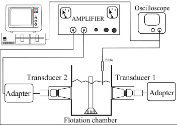
Because the problem is very complex it was necessary to make a design that avoid complications raising from different geometries that can be involved in. To deal with this problem, a specially designed normalized Denver flotation Cell with ultrasonic capabilities were designed and constructed. The Denver Cell was constructed in such a way that normalized flotation experiments can be done with the same geometry with and without ultrasonic activation. The ultrasonic source was mounted in such a way that it not disturb the whole process. The applied power and the working frequency was controlled for an specially designed electronic circuit [1].
With the Ultrasonic Denver Cell a number of flotation experiments with copper mineral from Chuquicamata CODELCO-CHILE with and without ultrasonic activation were carry out. To compare the results the recovered substances were chemically analyzed and the total recovering was assezed. In addition, the process kinetics were studied.
The results were promising but to obtain concluding results new experiments with chemical reagents specialized to the situation must be tested, also the best conditions for ultrasonic frequency would be very useful.
Material and Method
The Denver Cell was built in acrylic material. The experimental arrangement it is shown in the figure 1. The transducers are mounted in a sealed chamber filled with distilled water, in this way a good coupling between transducers and the metallurgic pulp is obtained. The chamber have a flat-mounted membrane in the Denver Cell wall to avoid perturbations in the process kinetics but allowing the acoustic field to go into it .The transducer frequency is approximately 18 kHz and the power capabilities goes up to 300 Watts.
three elements exist simultaneously in the region: particles (solid) water (liquid) and Bubbles (gases) was scanned. Second the medium plane, called the separation plane, because the particles with useful substances were classified and separated in this region And at last, the upper region, referred as the region of foam, formed with particles adhered to bubbles, rich in the product that we are interested in.
The measurement of acoustic field was done with a specially designed probe to work in a cavitating environment [4]. Using a non-linear technique the probe calibration was done for a wide range of frequencies [5]. To avoid excessive perturbation of the acoustic field the probe diameter must be as little as possible, in our case 2mm. The frequency range of the probe goes from 0.001 to 1 MHz.
A three dimensional picture of scanned acoustic field in the central plane of medium region is presented in the figure 2. It can be appreciated, a region without acoustic field in the middle of the scanned plane, it corresponds to the position of the "estator", a device to shake the pulp maintaining the suspension and with a air inlet to produce bubbles.
Oscilloscope
Probe
Adapter
Flotation chamber
AMPLIFIER
Adapter
Transducer 1
Transducer 2
IBM
Personal Computer Color Di splay
[image:3.595.128.480.440.690.2]P ersonal Comput er
0 2 4 6 8 10 12 14 0 2 4 6 8 10 12 14
HALF PLANE OF THE CELL
pressure (atm) 0 0.3000 0.6000 0.9000 1.200 1.500 1.800 2.100 2.400
front wall of the cell (cm)
[image:4.595.161.474.98.328.2]La te ra l wal l of the c el l ( cm) (i n that the tr an sd uc er s a re lo ca te d)
Fig.2 The acoustic field in the half plane of the chamber
As can be appreciated in the figure, the acoustic field is not very homogeneous, and also it is slightly asymmetric. In the central part of the scanned plane the acoustic field is as high as 2.4 atm. Because the high agitation degree, the pulp circulates by all the chamber in a low time scale and the asymmetry in acoustic field do not appear as a very disadvantageous fact.
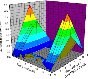
In the figure 3 a three dimensional picture of the treatment chamber it is shown. In this figure can be appreciated clearly that the acoustic field is increasing from the bottom, to the center of the chamber, in the halfway plane. In this plane the acoustic pressure values is maximum and going up it take decreasing values until the top of the reactor. This is a consequence of the design because an acoustic field too much strong in the upper part of the chamber would dissolve the foam and could spoil process efficiency.
0 2
4 6
8 10
12 14 0.1
0.2 0.3 0.4 0.5 0.6 0.7 0.8 0.9 1.0
0 2
4
6 8
1012
14
Ac
oust
ic pr
essu
re (
atm
)
Side w
all (cm)
(TRAN SDU
CERS)
[image:5.595.177.478.106.377.2]Front w all (cm)
Fig 3. Three dimensional acoustic field in flotation chamber
As can be appreciated in the figure, the acoustic field it is rather homogeneous, and also it is slightly asymmetric. In the central part of the scanned plane the acoustic field is as high as 2.4 atm. Because the high agitation degree, the pulp circulates by all the chamber in a low time scale and the asymmetry in acoustic field do not appear as very disadvantageous fact.
Because the chamber in the experiments was filled with metallurgic pulp, too much attenuating than distilled water, the acoustic field measurements must be considered only as an indication of the relative acoustic pressures.
the results are less interesting than at low pressure. It must be noted that the
.
0 20 40 60 80
30 40 50 60 70 80 90 100
Recovering (Fraction under 325 Tyler Mesh)
R
e
co
ver
ing (%)
Power (W)
[image:6.595.144.454.119.348.2]Cu Mo Fe
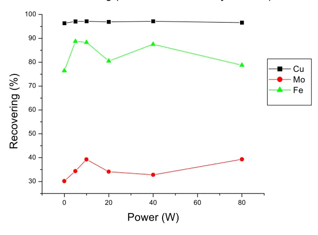
Fig. 4 results for flotation made at different applied powers
iron recovering, a non-desired product also goes up with the ultrasonic action By other hand, if the global recovering of useful substances that we are looking for it is considered (figure 5), it can be noted that interesting, the iron recovering goes down for the best values of the recovering in the substances that we are search it: the molybdenum and the copper. This is a very interesting experimental fact that suggest that the chemistry of the process under ultrasonic field must be considered.
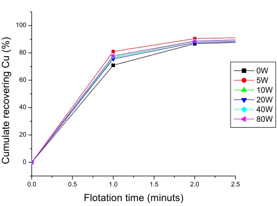
To have a complete picture of the new ultrasonic technique kinetics studies were done. In this experiments the recovering process are stopped a different times after the reactions begin, in this way it is apparent the chemical behavior of the substances that in the process are involved in. The results are shown in the figure 6.
after this process is finished, it is not relevant the application or not of ultrasound to the process.
0 20 40 60 80
60 65 70 75 80 85 90 95
Recovering of global concentrate
R
e
co
vering (%
)
Power (W)
[image:7.595.118.478.128.444.2]Cu Mo Fe
Fig. 5 The global recovering in ultrasonic experiments
0.0 0.5 1.0 1.5 2.0 2.5
0 20 40 60 80 100
The flotation kinetics
C
u
m
u
la
te
re
co
ve
rin
g
C
u (
%
)
Flotation time (minuts)
0W 5W 10W 20W 40W 80W
[image:7.595.158.439.510.719.2]Discussion and Conclussions
In this paper an application of ultrasound to flotation process it is explored. The obtained results show an improvement in the recovering quality of the process. The study shows that the kinetics of the process are also improved.
The growing in the law of the concentrates suggest some possible effect of superficial cleaning (superficial removal of oxides), tendency of the ultrasound to inhibit the trapping or hydrodynamic haulage of fine particles and ultrafine belonging to the bargain.
The analysis of the laws achieved in the fraction + and do -325 meshes of the concentrate show a similar behavior to that of the global concentrate and could give support to the previous considerations and would suggest the pursuit of this behavior in later studies.
The experimental conditions do not allowing the consideration of cavitation bubbles in the process but it is a aspect that really must be considered in the future, we are interested in the number and quality of the cavitaion bubbles in the flotation process.
It is possible that a factor that could be important in the improvement of the process is the improvement in the capture properties of the bubbles: the increase in the kinetics energy allowing the particle to adhere the bubble, the growing of collision probability between bubbles and particles and the effect, that can no be positive, of the free surface in the reactor, for this task a physique-chemical study must be conducted that allow to know the fundamentals of the process looking for its optimization.
Acknowledgment
The authors would like to thank the financial support of project FONDECYT 1010243.
References
[2] Bulatovic. S. M. Salter R. S. H. High intensity conditioning: a new approach to improve flotation of mineral slimes In: Conference of Metallurgist. Halifax. Canada Proceedings 1º989 pp182-197.
[3] M. D. Engel, P. D. Middlebrook and G. J. Jameson, Advances in the study of high intensity conditioning as a means of inproving mineral flotation performance, Mineral Engeneering, V10 Nº 1 pp 55-68 (1997)
[3] L. Gaete-Garretón et, Y. Vargas Hernández, F. Montoya Vitini, S. Pino Dubreouil, Ultrasonic Detectors for high-intensity acoustic fields
Sensors and Actuators A 37-38 pp 410-414 (1993).