ANN Based Tool Condition Monitoring System
for CNC Milling Machines
Sistema basado en redes neuronales artificiales para el monitoreo de
la herramienta en fresadoras CNC
Información del artículo: recibido: marzo de 2010, reevaluado: junio de 2010, aceptado: octubre de 2010
Mota-Valtierra G.C.
Laboratorio de Mecatrónica. Facultad de Ingeniería Universidad Autónoma de Querétaro
Email: g.motav@hotmail.com
Franco-Gasca L.A.
CIATEQ, A.C., LabCASD, QuerétaroE-mail: luis.franco@ciateq.mx
Herrera-Ruiz G.
Laboratorio de Mecatrónica. Facultad de Ingeniería Universidad Autónoma de Querétaro
Email: gherrera@uaq.mx
Macias-Bobadilla G.
Laboratorio de Mecatrónica. Facultad de Ingeniería Universidad Autónoma de Querétaro
Email: gonzalo.macias@uaq.mx
Abstract
Most of the companies have as objective to manufacture high-quality pro-ducts, then by optimizing costs, reducing and controlling the variations in its production processes it is possible. Within manufacturing industries a very important issue is the tool condition monitoring, since the tool state will determine the quality of products. Besides, a good monitoring system will protect the machinery from severe damages. For determining the state of the cutt ing tools in a milling machine, there is a great variety of models in the industrial market, however these systems are not available to all compa-nies because of their high costs and the requirements of modifying the ma-chining tool in order to att ach the system sensors. This paper presents an intelligent classifi cation system which determines the status of cutt ers in a Computer Numerical Control (CNC) milling machine. This tool state is mainly detected through the analysis of the cutt ing forces drawn from the spindle motors currents. This monitoring system does not need sensors so it is no necessary to modify the machine. The correct classifi cation is made by advanced digital signal processing techniques. Just after acquiring a signal, a FIR digital fi lter is applied to the data to eliminate the undesired noisy components and to extract the embedded force components. A Wavelet Transformation is applied to the fi ltered signal in order to compress the data amount and to optimize the classifi er structure. Then a multilayer percep-tron-type neural network is responsible for carrying out the classifi cation of the signal. Achieving a reliability of 95%, the system is capable of detecting breakage and a worn cutt er.
Keywords
• breakage • wear
Introduction
The aim of most of the companies is to satisfy the needs of its costumers by producing high quality products, optimizing costs and improving the manufacturing processes. So, in order to achieve the quality specifi ca-tions it is very important to eliminate variaca-tions during the production processes. For manufacturing compa-nies, the use of tool condition monitoring systems is mandatory in order to detect either breakage or wear on the tools. These systems avoid the production of poor quality pieces due to the state of the cutt ing tools and even prevent damage to the machines.
The techniques used in sound and vibration emis-sion sensing have the disadvantage of capturing signals from nearby equipment, making diffi cult to identify the desired information in the machining process. Image processing based monitoring systems have been al-ready developed; but with this kind of systems the mo-nitoring must be done off -line, stopping the process completely while the tool analysis is completed (Fran-co, 2008). The Artifi cial Neural Networks (ANNs) off er the possibility to work in parallel, making possible the real time monitoring.
In most of the reported methods and systems, the use of sensors is common (Prickett et al., 1999; Franco, 2008); however, the sensor selection is one of the most critical aspects in the system development, since its
application is limited by the operation range defi ned by the manufacturer specifi cations. Because of this, tool condition monitoring systems are fitt ed to certain specifi c working conditions that do not allow nor ease the adjustment to new manufacturing operations. Sin-ce the sensor approach presents the inconvenienSin-ce that each machine requires its own characteristic sen-sor system, adaptability becomes a desirable characte-ristic of any monitoring system. Because of its ability for adapting to changes, besides the big number of in-puts, all those problems do not occur with the use of ANNs.
For manufacturing companies the use of tool condi-tion monitoring systems is mandatory in order to de-tect either breakage or wear on the tools, and to avoid the production of poor quality pieces due to the state of the cutt ing tools and even prevent the damage to the machines.
In most of the reported methods and systems, the use of sensors is common; however, the sensor selection is one of the most critical aspects in the system develo-pment, since its application is limited by the operation range defi ned by the manufacturer specifi cations. The-refore, tool condition monitoring systems are fitt ed to certain specifi c working conditions that do not allow nor ease the adjustment to new manufacturing opera-tions. Since the sensor approach presents the inconve-nience that each machine requires its own characteristic
Resumen
Algunas empresas tienen como principal objetivo ofrecer a sus clientes productos de calidad, y esto es posible optimizando sus costos, reduciendo y controlando las va-riaciones en sus procesos de producción. Dentro de las industrias manufactureras el estado físico de las herramientas es muy importante, ya que de esto depende en gran medida la calidad del producto y la vida útil de la maquinaria. Actualmente existe en el mercado una gran variedad de sistemas de monitoreo para determinar el estado de los cortadores en las fresadoras; sin embargo, estos son costosos e inaccesibles para las empresas pequeñas y frecuentemente es necesario hacer modifi caciones a la ma-quinaria para instalarlos. En este artículo se presenta un sistema de monitoreo con un clasifi cador inteligente que determina el estado de las herramientas de corte en una fresadora de Control Numérico por Computadora (CNC). El estado de los cor-tadores se detecta a través del análisis de las fuerzas de corte que se encuentran contenidas en las corrientes del motor del husillo. Algo importante en este sistema es que no utiliza sensores ni es necesario hacer modifi caciones para adherirlo al proceso original. Para lograr la clasifi cación se aplican técnicas de procesamiento digital de señales, para eliminar los componentes de ruido y extraer los componentes de fuerza, se aplica a la señal original un fi ltro digital del tipo FIR. Después, se aplica una transformada Wavelet, con la fi nalidad de comprimir la información y optimizar el clasifi cador. Por último, una red neuronal del tipo perceptrón multicapa es la encar-gada de realizar la clasifi cación de las señales, alcanzando una confi abilidad del 95%. El sistema es capaz de detectar la ruptura y el desgaste del cortador.
Descriptores
• sistema de monitoreo
• ruptura
• desgaste
• transformada Wavelet
• redes neuronales artificiales
sensor system, adaptability becomes a desirable charac-teristic of any monitoring system, and this problem is not present in the monitoring system presented becau-se it does not have becau-sensors.
Thus this kind of systems is inaccessible for small companies, where the tool inspection is made by the operator of machinery, but a person does not guarantee the correct damage detection due to the inappropriate conditions such as lighting, noise, position of the tool, etc. For these reasons an intelligent system of low cost and easy incorporation to the original process is propo-sed. It is able to classify the physical condition of the cutt ing tool in a milling machine, helping to prevent de-fects in the working pieces and to avoid severe damage to the machine tool.
An intelligent system may be implemented with any of the artifi cial intelligent techniques such as arti-fi cial neural networks (ANNs), fuzzy system or heu-ristic algorithms. However, the use of ANNs to classify the state of the tools is widespread because of their adaptive learning, self-organization, fault tolerance and real-time operation, providing good solutions to classifi cation or decision making problems. Examples of ANNs applied to the tool condition classifi cation may be found in Rivero (2008), Mehrabian et al. (2008), Patra et al. (2007) and Kuljanic et al. (2009). Jantunen (2002) reported a summary of methods used to detect breakage and wear of the cutt ing tools, showing that cutt ing forces are commonly used to classify the tool wear, also, this fact may be appreciated in works pre-sented by Kuljanic et al. (2005), Rivero et al. (2008), Bhatt acharyya et al. (2007) and Jemielniak et al. (2008). In order to evaluate the cutt ing forces, Zuperl et al. (2004) and Kurt (2009) developed simulation models, these models determine the cutt ing forces with more precision than the analytical models due to the appli-cation of Multi Layer Perceptron (MLP) type ANNs.
Development Monitoring system
Literature suggests a big variety of parameters in ma-chining processes that can be used to characterize, to analyze and to predict the state of the cutt ing tools. In Prickett (1999), the monitoring mechanisms for detec-ting the tool condition are classifi ed either by the place or by the variable. Among the used variables are the cutt ing forces (static and dynamic), since it has been wi-dely established that forces variations are correlated to the tool wear. In practice the application and interpreta-tion of this parameter may be studied in several forms,
such as those based on the changes of the friction bet-ween the cutt ing tool and the work-piece (López et al., 2006; Shao et al., 2004). For this paper it was decided to analyze the cutt ing forces in order to determine the le-vel of tool wear.
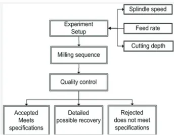
A retrofitt ed Tos kurim CNC milling machine, mo-del FNK25A, with a head tool of two carbide inserts was used for testing the intelligent classifi er. The co-rrect set up of cutt ing parameters is an important step of the milling process; the parameters selection de-pends on the material hardness, type of cutt er and work piece fi nish, among others. These choices will determi-ne whether or not the fi nal product meets the quality specifi cations (dimensions, fi nish, etc.). The stages that compose a milling process are show in fi gure 1.
The milling parameters are shown in table 1. The mi-lling process was made on ASTM-4130 steel, and using cutt ers of diff erent states such as new (good conditions), worn (with several degrees of wear) and broken. These parameters have a big infl uence in the milling process, for this reason they are considered important inputs in the ANN, these parameters are provided by the operator. Moreover, there are inputs to the system (cutt ing forces) which are acquired from the driver.
The values of spindle speed, depth of cut and feed rate were varied between the ranges shown in table 1 for
Parameter Value
Spindle speed 300 – 450 rpm
Cu ing depth 1 – 1.5 mm
Feed rate 100 - 120 mm / min
Figure 1. Stages of a milling process
each case. Driver current monitoring is the best appro-ach to acquire signals without sensors because this way the machine is not modifi ed, even when current sensors are used. In addition, the current from servomotors is available in almost all modern rotating machinery as turning, milling and drilling, directly from the servo-driver. Signals from the motor spindle driver Baldor series 15H are acquired for determining the cutt er sta-tus; these signals are a direct representation of the cut-ting forces, a Tektronik MSO4000 oscilloscope is the instrument used to acquire and store the signals during the process in order to create a data base, but it is used temporarily. Finally, to obtain the neural networks in-puts, a features extraction from the acquired data is made by digital signal processing techniques (fi gure 2).
Data acquisition
As mentioned before, the cutt ing forces will be the main parameter to be analyzed. According to Prickett (1999) one of the points where is possible to acquire these sig-nals is the spindle motor. Thus for avoiding the use of sensors, in this research the motor driver is proposed as the data source. The original signal presents the cutt ing force as its main component; however, it is important to mention that signals from the servo driver have severe noise interference by the ball-screw and the switching noise due to the associated digital systems (Romero et al., 2003). Therefore, previously to the digital proces-sing it is necessary to fi lter the spindle current signals. Figure 3 shows the signal processing system, which was used to obtain the cutt ing forces.
To eliminate the noisy components, the original signal is fi ltered using a band-pass fi lter. A Finite Impulse Response (FIR) digital fi lter was chosen because it has a linear phase response. Table 2 contains the parameters
of the applied fi lter; this was designed using the fi lter design and analysis tool from MatLab.
In order to determine the fi lter characteristics for this ANN-based tool condition monitoring system, two previous researches were applied. In Romero et al.
(2003) a driver current analysis for the milling machine is presented; it has been shown that cutt ing forces are in a frequency range of 1-10 KHz. The choice of the sam-pling frequency is determined by both the characteris-tics of the acquisition system and the signal processing technique. And then from a fi ltering analysis (Franco et al., 2008) for several techniques and machining proces-ses is found that the appropriate order fi lter for this kind of signals is around 40.
Figure 4 displays an unfi ltered signal a) and its co-rresponding fi ltered signal b). As can be seen the fi lte-ring process removes the noisy components and preserves the embedded cutt ing force.
To consolidate the classifi cation process a data com-pression procedure is performed. This is done by the Wavelet Transform (WT), which implements a map-ping of the time-domain to a time-scale representation, preserving the temporal aspect. Figure 5 shows a signal with diff erent compression levels by applying a Daube-chies-5 Wavelet function; it can be observed that those levels have the same patt ern but a diff erent resolution. The maximum transformation level is determined by the desired data compression which results in a signal without loss of information and resolution for the next processing stage, as showed in previous research (Fran-co et al., 2009; Romero et al., 2003), for this study the fi fth level was selected, this allows to achieve a data reduc-tion from 1024 to only 32 points per sample.
Figure 2. Stages of the monitoring system
Figure 3. Experiment setup
Filter characteristics
Filter type Bandpass
Design method Kaiser window
Sampling frequency 6250 Hz
Order Filter 30
Intelligent classification
In order to select the optimal network for classifi cation of the tool state, several Multi Layer Perceptron (MLP) type networks with supervised training were tested. As well as Self-Organizing Maps (SOM) with both super-vised and unsupersuper-vised training, this represents a sig-nifi cant variation because SOM networks are usually unsupervised trained. Some of the tested MLP networ-ks included the [4, 10, 10, 3], [4, 8, 8, 3], [4, 8, 12, 3] and [4, 8, 10, 3] structures. Figure 6 shows one of the MLP tested. The activation function is a sigmoid function and learning rate of 0.2.
It was decided to test a SOM network as classifi er, due to its low sensitivity to noise; it is an appropriate
tool to classify this kind of signals. Some of the analy-zed structures were [4, 4], [4, 8] and [8 8], these were trained using both supervised and unsupervised lear-ning. The supervised training was made adding a su-pervisor agent, which is an array of [N 1], where N is the number of existing classes. Figure 7 shows a [4, 4] SOM network with a neighborhood of 1.
The classifi er was tested using two diff erent kinds of ANNs with diff erent size and training types. The MLP networks were preferred because their training is faster than the training of the SOM networks. There are diff e-rences in the networks performance, but they are not sig-nifi cant. As summary, the table 3 shows the achieved error during the training of the MLP networks.
Figure 8 shows the way as the error decreases, and it can be seen that there is not an important diff erence among the obtained errors when the number of neu-rons in the hidden layers is bigger than eight. So that, the neural network that is considered as suitable for using in the proposed intelligent classifi er should have at less eight neurons in the hidden layers. For valida-ting the network performance two types of inputs were tested, signals previously used during the training and signals not used for the training process.
Figure 5. Data compression levels. The Y-axis represents the cutting force and the X-axis is the sample number
Figure 4. a) Unfiltered signal, b) Filtered signal
For testing the monitoring system were used both new and worn cutt ing tools. Some of the worn cutt ers were used during the training. To guarantee a good classifi -cation system it must identify either a broken or worn cutt er. Figure 9 shows some results of correct identifi -cations.
Conclusions
In this paper the cutt ing force variations have been co-rrelated to the tool wear by using an Artifi cial Neural Network, as a consequence the correct classifi cation of the cutt ing tool condition is achieved. This ANN appro-ach has made possible the online and fault tolerant mo-Cu ing
depth (mm)
Feed rate (mm/min)
Spindle speed (rpm)
Epoch Neuron in hidden layers
Error
1 100 300 1000 [8,8] 0.001397
1 100 450 1000 [8,8] 0.001298
1 120 300 1000 [10,10] 0.00099
1 120 450 1000 [10,10] 0.00099
1.5 100 300 1000 [8,10] 0.00099
1.5 100 450 1000 [8,10] 0.00099
1.5 120 300 1000 [8,12] 0.00099
1.5 120 450 1000 [8,12] 0.00099
Figure 7. SOM-type artificial neural network
Table 3. Error of MLP networks
Figure 8. Error during neural network training
nitoring of the tool, besides the system presents the advantage of not having to stop the machine for knowing the tool condition. From test using both net-works types, MLP and SOM, the MLP obtained a bett er percentage of correct classifi cations and a faster conver-gence. The presented tool condition monitoring system does not need sensors, thus the machinery will not be modifi ed if the system is att ached to its structure.
It is possible to state that there is not a signifi cant diff erence in the achieved error when the neural net-works have more than 8 neurons in their hidden la-yers; however, computationally it represents a consi-derable diff erence in resources consumption, for that reason is not appropriate to comprise more than 8 neurons per layer. So this is the suitable size for a net-work which is going to be considered as classifi er in the proposed system.
The proposed neural network is able to classify breakage levels greater than 0.5 mm with a confi dence level of 95%; with the same confi dence level it also de-termines the good condition of the tool. The wear tool can be resolved with an effi ciency of 93% when the wear is greater than 0.25 mm. Its reliable confi dence le-vel avoids the damage to the machinery, the tool and the piece, which is the main objective of a tool condition monitoring system. In the worst case if the monitoring system fails the workpiece will need to be re-worked with a new cutt ing tool, since the damage will be just a piece of a lower quality fi nish. Future work will try to identify two levels of wear tool, in addition to the breakage and the good working conditions.
The maximum compression level of the signal was achieved with fi ve levels of data processing. To verify that the original signal may be recovered, an inverse wavelet transformation was made, verifying that the signal is completely recoverable.
Acknowledgments
The fi rst author would like to thank to CONACyT for supporting this work under scholarship number 173432.
References
Bhatt acharyya P., Sengupta D., Mukhopadhyay S., Cutt ing Force-Based Real-Time Estimation of Tool Wear in Face Milling Us-ing a Combination of Signal ProcessUs-ing Techniques. Mechanical Systems and Signal Processing, 21:2665–2683, 2007.
Franco-Gasca L.A., Romero-Troncoso R. de A., Herrera-Ruiz G., Peniche-Vera R. del R. Reconfigurable Filtering System for Sensorless Signal Acquisition in Machining Processes. Inte
r-national Journal of Advanced Manufacturing Technology,
38:102-109, 2008.
Franco-Gasca L.A., Romero-Troncoso R. de A., Herrera-Ruiz G., Peniche.Vera R. del R. FPGA Based Failure Monitoring Sys-tem for Machining Processes. International Journal of Advanced
Manufacturing Technology, 40:676-686, 2009.
Jantunen E. A Summary of Methods Applied to Tool Condition Monitoring in Drilling. International Journal of Machine Tools &
Manufacture, 42:997-1010, 2002.
Jemielniak K., Arrazola P.J. Application of AE and CuĴ ing Force
Sig-nals in Tool Condition Monitoring in Micro-Milling.CIRP Journal
of Manufacturing Science and Technology, 1:97-102, 2008. Kuljanic E., Totis G., Sortino M. Development of an Intelligent
Multisensor Chatt er Detection System in Milling. Mechanical Systems and Signal Processing, 23:1704-1718, 2009.
Kurt A. Modelling of the Cutt ing Tool Stresses in Machining of Inconel 718 Using Artifi cial Neural Networks. Expert Systems with Applications, 36(6):9645-9657, 2009.
Kuljanic E., Sortino M. A Method Based on Cutt ing Forces Moni-toring Tool Wear in Face Milling. International Journal of Ma-chine Tools & Manufacture, 45:429–34, 2005.
López de Lacalle L.N., Lamikiz A., Sánchez J.A., Fernández de Bustos I. Recording of Real Cutt ing Forces Along the Milling of Complex Parts. Mechatronics, 16:21–32. 2006.
Mehrabian A., Menha-Mohammad B. A Real-Time Neuro-Adap-tive Controller with Guaranteed Stability. Applied Soft Compu-ting, 8:530–542, 2008.
Patra K., Pal-Surjya K, Bhatt acharyya K. Artifi cial Neural Network Based Prediction of Drill Flank Wear From Motor Current Sig-nals. Applied Soft Computing, 7:929–935, 2007.
Prickett P.W., Johns C. An Overview of Approaches to End Mi-lling Tool Monitoring. International Journal of Machine Tools & Manufacture, 39:105-122, 1999.
Rivero A., Lopez de Lacalle L.N., Penalva M.L. Tool Wear Detec-tion in Dry High-Speed Milling Based Upon the Analysis of Machine Internal Signals. Mechatronics, 18(10):627-633, 2008. Romero-Troncoso R.J., Herrera-Ruiz G., Terol-Villalobos I.,
Jáure-gui-Correa J.C. Driver current Analysis for Sensorless Tool Breakage Monitoring of CNC Milling Machines. International Journal of Machine Tools & Manufacture, 43:1529–1534, 2003. Shao H., Wang H.L., Zhao X.M. A Cutt ing Power Model for Tool
Wear Monitoring in Milling. International Journal of Machine Tools & Manufacture, 44:1503-1509, 2004.
About the authors
Georgina del Carmen Mota-Valtierra. She is an electronics engineer graduated from the Technological Institute of Celaya, Mexico. She received her M.Sc. degree in digital electronics from the Technological Institute of Celaya, Mexico, in 2008. She is a Ph.D. student and professor in the Faculty of Engineering in the University of Que-retaro. Her current research interests are design of FPGA-based systems and artifi -cial intelligent.
Luis Alfonso Franco-Gasca. He received his M.Sc. degree from the University of Gua-najuato, Mexico, in 2000, his Ph.D. degree from the Autonomous University of Queretaro, Mexico, in 2007. Currently, he is a researcher in the Automatic Control and Dynamic Systems Laboratory at the Advanced Technology Center, CIATEQ (Queretaro, Mexico). He is member of the National Researchers System (SNI). His main current research interests include digital signal processing, intelligent control algorithms and FPGA embedded systems applications.
Gilberto Herrera-Ruiz. He received his B.Sc. degree in electronic systems engineering, his M.Sc. degree in electrical engineering and his Ph.D. degree in mechanical engi-neering. He is member of the National Researchers System (SNI) level II. Currently, He is the principal of the Faculty of Engineering in the Autonomous University of Queretaro. His current research interests include automation of machine tools, di-gital signal processing and control systems.