c
I N S T I T U T O T E C N O L Ó G I C O Y D E E S T U D I O S S U P E R I O R E S D E M O N T E R R E Y
P R E S E N T E .
-Por medio de la presente hago constar que soy autor y titular de la obra denominada
, en los sucesivo LA OBRA, en virtud de lo cual autorizo a el Instituto
Tecnológico y de Estudios Superiores de Monterrey (EL INSTITUTO) para que efectúe la divulgación, publicación, comunicación pública, distribución, distribución pública y reproducción, así como la digitalización de la misma, con fines académicos o propios al objeto de EL INSTITUTO, dentro del círculo de la comunidad del Tecnológico de Monterrey.
El Instituto se compromete a respetar en todo momento mi autoría y a otorgarme el crédito correspondiente en todas las actividades mencionadas anteriormente de la obra.
De la misma manera, manifiesto que el contenido académico, literario, la
Development of a Language for Robot-Based Assembly Domain
-Edición Única
Title Development of a Language for Robot-Based Assembly Domain -Edición Única
Authors Yasmín Sarahí Villegas Hernández
Affiliation Tecnológico de Monterrey, Campus Monterrey
Issue Date 2011-12-01
Item type Tesis
Rights Open Access
Downloaded 18-Jan-2017 14:46:38
Development of a Language for Robot-based
Assembly Domain
por
Ing. Yazm´ın Sarah´ı Villegas Hern´
andez
Tesis
Presentada al Programa de Graduados de la Escuela de Ingenier´ıa y Tecnolog´ıas de Informaci´on como requisito parcial para obtener el grado acad´emico de
Maestro en Ciencias
especialidad en
Sistemas de manufactura
Instituto Tecnol´
ogico y de Estudios Superiores de Monterrey
Campus Monterrey
INSTITUTO TECNOLÓGICO Y DE ESTUDIOS SUPERIORES
DE MONTERREY
CAMPUS MONTERREY
ESCUELA DE INGENIERÍA Y TECNOLOGÍAS DE LA INFORMACIÓN
Los miembros del Comité de Tesis recomendamos que la presente Tesis de la Ing. Yazmín Sarahí Villegas Hernández sea aceptada como requisito parcial para obtener el grado académico de Maestro en Ciencias con especialidad en:
SISTEMAS DE MANUFACTURA
Dr. Guillermo Jiménez Pérez Sinodal
Dr. Ciro Ángel Rodríguez González Director de la Maestría en Ciencias con Especialidad en Sistemas de Manufactura
Reconocimientos
Al Dr. Federico Guedea por toda su confianza, apoyo y paciencia. Por compartir conmigo sus conocimientos, ideas y su tiempo.
Dr. Guillermo Jiménez por sus valiosos comentarios y retroalimentación en la perspectiva científica de este trabajo de investigación.
M.C. Luis Vicente Cabeza por compartir conmigo sus comentarios y su tiempo.
YAZMÍN SARAHÍ VILLEGAS HERNÁNDEZ
Abstract
This thesis research presents the implementation of a programming language to describe a Robot-based assembly and welding domain using tools as planners and parser in order to generate plans for robots. This programming language is used to describe an automated robotic-workcell. In this thesis, using this language, a plan can be generated, which is parsed in order to obtain a robot program for the pick-and-place task. The idea is to use the plan written in a high-level-language in order to get a generic-low-level-language robot program for pick-and-place task, using a planner and a parser.
The generation of robot program works as follows: First, the planner generates a plan using the language developed. Second, the parser changes the high-level-language plan to a generic-low-level-language. Some examples are provided of the tests performed in this thesis.
Contents
Reconocimientos
List of Tables iv
List of Figures v
Chapter 1 Introduction 1
1.1 Motivation 1 1.2 Problem statement 2
1.3 Scope of the thesis 2 1.4 Thesis Objectives 2
1.4.1 General objective 2 1.4.2 Specific objectives 3
1.5 Hypothesis 3
Chapter 2 State of Art 4 2.1 Automatic planning in Shipbuilding 4
2.2 Process planning systems 5
2.3 CAPP System 6
Chapter 3 Planners 9
3.1 SatPlan 9 3.1.1 How SatPlan works? 9
3.2 Graphplan 10 3.2.1 How Graphplan works? 10
3.3 Blackbox 14 3.3.1 How Blackbox works? 14
3.4.5 HTN . . . 15
Chapter 4 Welding 16 4.1 Type of Welds . . . 16
4.2 Joint designs . . . 18
4.3 Welding positions . . . 22
4.4 Welding processes . . . 22
4.4.1 Oxyfuel-Gas Welding (OFM) . . . 23
4.4.2 Arc-Welding processes:Nonconsumable electrode . . . 23
4.4.3 Arc-Welding Processes:Consumable Electrode . . . 25
4.4.4 Electron-beam welding . . . 28
4.4.5 Laser-beam welding . . . 30
Chapter 5 Automatic Planner system 31 5.1 Problem Definition . . . 31
5.2 The Planner system . . . 31
5.2.1 High-level-language Planner system . . . 31
5.2.2 Generic-Level-Language Parser subsystem . . . 44
5.2.3 Wrapper Dynamic-Link Library . . . 47
5.2.4 Wrapper-generic-level-language-functions program . . . 48
5.2.5 Graphic-User-Interface for the Automatic Planner system . . . . 50
Chapter 6 Experimental tests 51 6.1 Planner Tests . . . 51
6.1.1 Graphplan planner . . . 51
6.1.2 Graphplan-PDDL planner . . . 92
6.2 Translator Tests . . . 108
6.2.1 First phase . . . 110
6.2.2 Second phase . . . 110
6.2.3 Third phase . . . 113
6.3 System Tests . . . 119
6.3.1 Phase 1 . . . 120
6.3.2 Phase 2 . . . 124
6.3.3 Phase 3 . . . 130
6.3.4 Phase 4 . . . 136
Chapter 7 Conclusions 150 7.1 Initial questions . . . 150
7.2 Limitations . . . 151
7.3 Scope of applicability . . . 152
7.5 Future research . . . 152
Appendix A Operators developed for the Graphplan planner 155 A.1 Operators for phase 1 . . . 155
A.2 Operators for phase 2 . . . 157
A.3 Operators for phase 3 . . . 159
A.4 Operators for phase 4 . . . 161
A.5 Operators for phase 5 . . . 163
A.6 Operators for phase 6 . . . 165
A.7 Operators for phase 7 . . . 167
A.8 Operators for phase 8 . . . 170
A.9 Operators for phase 9 . . . 173
Appendix B Operators developed for the PDDL planner 176 B.1 Operators for phase 1 . . . 176
B.2 Operators for phase 2 . . . 178
B.3 Operators for phase 3 . . . 180
B.4 Operators for phase 4 . . . 181
B.5 Operators for phase 5 . . . 183
B.6 Operators for phase 6 . . . 185
B.7 Simulators . . . 186
List of Tables
5.1 Object types . . . 34
5.2 Domain literals . . . 35
5.2 (Domain literals ) . . . 36
5.4 List of operators . . . 36
5.4 (List of operators ) . . . 37
5.4 (List of operators ) . . . 38
5.4 (List of operators ) . . . 39
5.3 Goal literlas . . . 40
5.5 PickAndPlace operator . . . 41
5.6 Welding operators . . . 42
5.7 List of grammar rules for this thesis syntax . . . 45
5.8 List of Generic-Level-Language-Parse commands . . . 47
6.1 Comparative table of domains in different phases . . . 52
6.1 (Comparative table of domains in different phases ) . . . 53
6.2 Comparative table of goals in different phases . . . 54
6.3 Comparative table of objects in different phases . . . 54
6.3 (Comparative table of goals in different phases ) . . . 55
6.4 Comparative table of operators in different phases . . . 55
6.4 (Comparative table of operators in different phases ) . . . 56
6.5 Comparative table of predicates or literals in different phases . . . 93
6.6 Comparative table of functions in different phases . . . 93
6.7 Comparative table of operators in different phases . . . 94
6.8 Table of objects used in all the phases . . . 94
6.9 Tube types . . . 124
6.10 Tube types . . . 130
7.1 Features of the planners . . . 152
List of Figures
3.1 Planning graph structure . . . 11
3.2 Planning graph components . . . 11
3.3 Mutual exclusion relations . . . 12
3.4 Domain of the dinner date example . . . 13
3.5 Graphplan algorithm . . . 13
4.1 Concave fillet weld . . . 17
4.2 Convex fillet weld . . . 17
4.3 Fillet weld parts . . . 18
4.4 Kinds of groove weld . . . 19
4.5 Groove weld parts . . . 19
4.6 Groove angle types and bevel angle types . . . 20
4.7 Plug and slot welds . . . 20
4.8 Multi-pass welds . . . 21
4.9 Relationship between joint designs and welding positions . . . 21
4.10 Oxyfuel-gas welding . . . 23
4.11 Gas tungsten-arc welding . . . 24
4.12 Plasma-arc welding . . . 24
4.13 Atomic-hydrogen welding . . . 25
4.14 Shielded metal-arc welding . . . 26
4.15 Submerged-arc welding . . . 27
4.16 Gas metal-arc welding . . . 27
4.17 Flux-cored arc welding . . . 28
4.18 Electrogas welding . . . 29
4.19 Electroslag welding . . . 29
4.20 Electron-beam welding . . . 30
4.21 Laser-beam welding . . . 30
5.1 Automatic Planner System . . . 32
5.2 PickAndPlace operator execution . . . 43
5.4 High-level-language commands parsed to Generic-level-language
com-mands . . . 47
5.5 Wrapper-Dynamic-Link-Library Package diagram . . . 48
5.6 Wrapper-generic-level-language-functions program . . . 49
5.7 GUI for the Automatic Planner system . . . 50
6.1 Workcell with one robot to do pick-and-place and welding operations . 57 6.2 Object for phase 1 . . . 58
6.3 Plan generated using operators of phase 1 . . . 58
6.4 Facts to test operators of phase 1 . . . 59
6.5 Goal to test operators of phase 1 . . . 60
6.6 pickANDplace operator execution . . . 61
6.7 Operators: doPutGripper and doPutWeldtool . . . 61
6.8 Operator:doHorizontalWeld . . . 62
6.9 Operator:doVerticalWeld . . . 63
6.10 Objects in phase 2 . . . 64
6.11 Plan generated using operators of phase 2 . . . 64
6.12 Facts to test operators of phase 2 . . . 65
6.13 Goal to test operators of phase 2 . . . 65
6.14 pickANDplaceAssembly operator execution . . . 67
6.15 Operator: doDiagonalWeld . . . 68
6.16 Workcell with two robots: a pick-and-place robot and a welding robot . 69 6.17 Plan generated using operators of phase 3 . . . 70
6.18 Facts to test operators of phase 3 . . . 70
6.19 Goal to test operators of phase 3 . . . 71
6.20 Example of objects used in phase 4 . . . 72
6.21 Plans generated using operators of phase 4 . . . 73
6.22 Facts to test operators of phase 4 . . . 74
6.23 Goals to tests operators of phase 4 . . . 74
6.24 Graphical representation of the execution of the (offsetxm t1 t2) operator 75 6.25 Graphical representation of the execution of the (offsetym t1 t2) . . . . 75
6.26 Graphical representation of joint types . . . 76
6.27 Graphical representation of the operators offsetx and offsety . . . 77
6.28 Plan generated using operators of phase 5 . . . 78
6.29 Facts to test operators of phase 5 . . . 79
6.30 Goal to test operators of phase 5 . . . 79
6.31 Example of the execution of the operator (rotateObj t1 180) . . . 80
6.32 Welding table in phase 6 with the fasteners . . . 80
6.33 Plan generated using operators of phase 6 . . . 81
6.35 Goal to test operators of phase 6 . . . 82
6.36 Edge Types for a TUBE . . . 83
6.37 Plan generated using operators of phase 7 . . . 84
6.38 Facts to test operators of phase 7 . . . 85
6.39 Goal to test operators of phase 7 . . . 85
6.40 Corner joint formed with the operators of welding (weldingCorner90, weldingCorner90ox and weldingCorner90oy) . . . 86
6.41 T joint formed with the operators of welding (weldingT90ox and weld-ingT90oy) . . . 87
6.42 Butt joint formed with the operators of welding . . . 87
6.43 Plan generated using operators of phase 8 . . . 88
6.44 Facts to test operators of phase 8 . . . 89
6.45 Goal to test operators of phase 8 . . . 89
6.46 Facts to test operators of phase 9 . . . 90
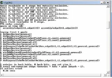
6.47 Plan generated using operators of phase 9 . . . 91
6.48 Goal to test operators of phase 9 . . . 91
6.49 Example of a literal in order to establish equality between the fastener space and the tube length:(equal tc0 f0) . . . 92
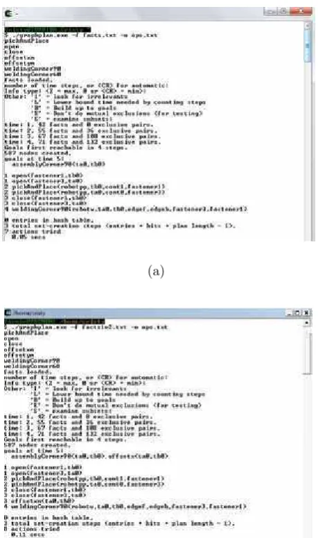
6.50 Facts to test operators of phase 1 . . . 95
6.51 Plan generated using operators of phase 1 . . . 96
6.52 Goal to test operators of phase 1 . . . 96
6.53 pickANDplaceAssembly operator execution . . . 97
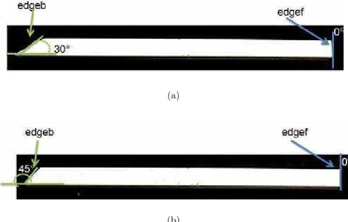
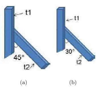
6.54 Corner Joint with two tubes with cut angle of 45◦ . . . . 98
6.55 Plan generated using operators of phase 2 . . . 99
6.56 Facts to test operators of phase 2 . . . 100
6.57 Goal to test operators of phase 2 . . . 100
6.58 Plan generated using operators of phase 3 . . . 101
6.59 Facts to test operators of phase 3 . . . 102
6.60 Goal to test operators of phase 3 . . . 102
6.61 Execution of the operators of offset . . . 103
6.62 Plan generated using operators of phase 4 . . . 104
6.63 Facts to test operators of phase 4 . . . 104
6.64 Goal to test operators of phase 4 . . . 105
6.65 Execution of the operators of offset . . . 106
6.66 Plan generated using operators of phase 5 . . . 106
6.67 Facts to test operators of phase 5 . . . 107
6.68 Goal to test operators of phase 5 . . . 107
6.69 Plan generated using operators of phase 6 . . . 108
6.70 Facts to test operators of phase 6 . . . 109
6.72 High-level-language commands translated to ABB-Robot-language
com-mands . . . 111
6.73 Interface of the class PickPlace . . . 112
6.74 High-level-language commands parsed to Generic-level-language com-mands . . . 113
6.75 Class Parser in second phase . . . 114
6.76 High-level-language commands parsed to Generic-level-language com-mands . . . 115
6.77 Class Parser in third phase . . . 116
6.78 Wrapper-generic-level-language Interface:RobotWrapper . . . 117
6.79 Robot Class Library . . . 118
6.80 Robot Library . . . 119
6.81 First-phase facts . . . 121
6.82 First-phase place positions . . . 121
6.83 First-phase goal . . . 122
6.84 First-phase plan . . . 122
6.85 First-phase program generated by the parser system . . . 123
6.86 First-phase assembly . . . 124
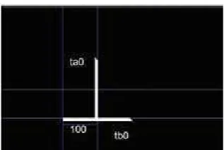
6.87 Container with tubes ta and tb . . . 125
6.88 Second-phase facts . . . 126
6.89 Second-phase place positions . . . 126
6.90 Second-phase goal . . . 127
6.91 Second-phase plan . . . 127
6.92 Second-phase program generated by the parser system . . . 128
6.93 Second-phase assembly . . . 129
6.94 Container with tubes ta, tb, tc and td . . . 130
6.95 Third-phase facts . . . 131
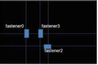
6.96 Third-phase table with fasteners . . . 132
6.97 Third-phase goal . . . 133
6.98 Third-phase plan . . . 133
6.99 Third-phase program generated by the parser system . . . 134
6.100Third-phase assembly . . . 135
6.101Fourth-phase: First-test facts . . . 137
6.102Fourth-phase: First-test table with fasteners . . . 137
6.103Fourth-phase: First-test goal . . . 138
6.104Fourth-phase: First-test plan . . . 139
6.105Fourth-phase: First-test program generated by the parser system . . . . 140
6.106Fourth-phase: First-test assembly . . . 140
6.107Fourth-phase: Second-test facts . . . 141
6.109Fourth-phase: Second-test goal . . . 143
6.110Fourth-phase: Second-test plan . . . 143
6.111Fourth-phase: Second-test program generated by the parser system . . 144
6.112Fourth-phase: Second-test assembly . . . 145
6.113Fourth-phase: Third-test facts . . . 146
6.114Fourth-phase: Third-test table with fasteners . . . 147
6.115Fourth-phase: Third-test goal . . . 147
6.116Fourth-phase: Third-test plan . . . 148
6.117Fourth-phase: Third-test program generated by the parser system . . . 149
Chapter 1
Introduction
This thesis presents a programming language to describe a Robot-based assembly and welding domain, which is used with a planner in order to automatically generate plans. In order to have a practical use of the plans in STRIPS-style in pick-and-place task, it was used a parser generator in combination with a wrapper program to generate and use a robot program for a pick-and-place robot.
Researchers have proposed different alternatives to automate the planning process for assembly operations. These researchers focused in semi-automated process, where the human knowledge is used to produce a solution. Furthermore, there are a few studies in this area, and the systems developed for assembly planning focused in solving a different problem, so the alternatives proposed are quite different.
In this chapter it is explained the reason of the research in the area of assembly planning, the specific problem to be addressed, the objectives in this thesis and the scope of this thesis.
1.1
Motivation
1.2
Problem statement
Automatic planning is an area of artificial intelligence that has several research articles, most of them focused in the development of algorithms for the generation of plans for a domain. To generate the plans it is necessary to have an already developed language in order to describe the domain of the problem. The language developed in the planning field has no further practical use. Most of the programming languages solve simple problems as the block world.
The block world is the most famous planning domain in artificial intelligence. It refers to a set of cubes that are placed in a table, in which the goal is to build one or more vertical stacks of blocks. In the same way most of the domains developed work as the block world; all these domains do not have a practical use.
Therefore, this thesis research is focused in the development of a language in order to describe a robot-based assembly-welding domain, which will have further practical use. For the development of this programming language, this research must answer the next questions:
• How to automatically generate a robot program for an assembly-welding domain?
• How to describe the assembly-welding domain?
• What are the actions necessary in an automated robotic-workcell?
1.3
Scope of the thesis
The research performed in this work concentrates in the development of a pro-gramming language to describe a Robot-based assembly and welding domain. In order to give a practical use to the plan already generated, it is developed a parser generator for the generation of a robot program for pick-and-place task.
The language developed describes a Robot-based assembly and welding domain, in order to generate plans for scheduling assembly operations. The generated plan is used for generating a robot program. So, the planning process is automated using the tools: planner, parser generator,and wrapper program.
1.4
Thesis Objectives
1.4.1
General objective
language takes into account common welding joints and the objects used in an auto-mated robotic-workcell. Also, the generated plans should be accomplished in a logical and sequential order.
1.4.2
Specific objectives
• Use of free software to construct the system.
• Use of a programming language to describe a robot-based assembly-welding do-main.
• Use of a generic a planner to generate a high level plan.
• Development of a generator to translate high level instructions to specific generic-level instructions for the robot.
• Wrappping all the robot instructions of a dynamic library in order to be used in c#.
1.5
Hypothesis
Chapter 2
State of Art
In this section the State of art of automatic planning is presented. It described the research in automatic planning in the shipbuilding industry. It is also described the research in the automatic planning of welding processes in a diversity of products, not only shipbuilding.
2.1
Automatic planning in Shipbuilding
The article “An automated welding operation planning system for block assem-bling in shipbuilding ”[1] describes the development of an automated welding operation planning system for block assembly in shipbuilding. Based on the information about the parts and their topological relationship with the assembly sequences for blocks, the system determines the welding postures, methods, equipment and materials. This system is already successfully implemented for real blocks constructed in shipyard.
The article “An Automatic Process-Planning System for Block Assembly in Ship-building ”[2] deals with the development of an automatic process planning system for block assembly in shipbuilding. A Part assembly graph (is a semantic network type of representation scheme for block structure) is proposed and used to represent block’s information. The approaches adopted are case-based reasoning for block assembly pro-cess planning and rule-based reasoning for propro-cess planning of cutting and welding operations. The prototype system has been implemented and verified using real blocks in the block assembly shop.
process planning and scheduling, a powerful heuristic is developed by employing an entropy-based partitioning method for identifying bottleneck periods. The experimen-tal results with data from a real shipyard show that the search heuristics developed are very effective and efficient.
The article “Block assembly planning in shipbuilding using case-based reasoning”[4] describes a process planning system using case-based reasoning (CBR) developed for block assembly in shipbuilding. A block assembly planning problem is modeled as a constraint satisfaction problem where the precedence relations between operations are considered constraints. In order to find similar cases, they propose two similarity co-efficients for finding similar cases and for finding similar relations. Due to the limited number of operation types, the process planning system first matches the parts of the problem and those of the case-based on their roles in the assembly, and then it matches the relations related to the matched partpairs. The parts involved in more operations are considered first. The process planning system is applied to simple examples for verification and comparison. A graphical user interface system is also developed for extracting information from CAD model, for preparing data for process planning, and for visually verifying the assembly sequence.
2.2
Process planning systems
The article “CAPABLE: an aggregate process planning system for integrated prod-uct development”[5] describes a new, time-based process planning architecture that consists of three levels corresponding to aggregate, management and detailed planning. The Concurrent Assembly and Process Assessments Blocks for Engineering manufac-ture (CAPABLE) is an aggregate process planning tool-kit which is designed to support the integrated product development process from its early stages. The main functions of CAPABLE relate to: the identification of production technology requirements, process and equipment selection, production route generation, evaluation of factory configura-tion and the rapid evaluaconfigura-tion of what-if scenarios concerning product configuraconfigura-tion and processing options. An initial testing phase has been completed in close collaboration with the industrial partner with very encouraging results.
for abstracting necessary product data from STEP (Standard for the Exchange of Product) files and directly from a proprietary CAD system are also discussed.
The article “An integrated design and planning environment for welding Part 2: Process planning”[7] describes the specification and implementation of aggregate pro-cess planning methods for complex welding operations. The methods are implemented as an aggregate process planning tool, CAPABLE/Welding, which can be used to eval-uate the manufacturability of complex fabrications at the early stages of design.
The article “An artificial intelligence approach for generating assembly sequences in CAD/CAM”[8] presents an innovative artificial intelligence approach for generating assembly sequences on a consortium of database emulating expert systems. Procedures include shape and feature recognition using a model-based CAD (computer-aided de-sign) analyzer, data structure and data modeling, knowledge-based representation, and inference processing through a set of heuristics and rules. The main tool here is an object-oriented concept as a means for managing geometrical data, topological data and abstraction. Abstractions added to data semantics help to build a knowledge base to meet assembly requirements. As a result, an AI paradigm supports knowledge pro-cessing for the search of good solutions and good decisions in the assembly process. An efficient implementation of the integrated system has been achieved and successfully demonstrated by results based on parts with varying complexities.
2.3
CAPP System
The article “An Intelligent Computer-Aided Assembly Process Planning System”[9] presents an intelligent computer-aided assembly process planning system (ICAAPP) de-veloped for generating an optimal assembly sequence for mechanical parts. The system employs a graph set technique for creating an assembly model. The set includes an attributed topological graph, an attachment constraint graph, a tolerance graph and a special process constraint graph. In generating assembly sequences for any product, the critical problems to be addressed include determining the base part, subassemblies selection, defining all necessary constraints, and quantifying and solving these con-straints. In the ICAAPP system, algorithms have been developed for the selection of the base part, defining the subassemblies, and determination of the constraint values.
well-organised structure of the program layout for achieving improved sharing of VR resources.
The article “A planning architecture for mobile robotics ”[11] presents an archi-tecture that integrates two planners for path planning and task planning for mobile robots such as explorer rovers. A path planner is used to plan the robot movement. Further, a task planner is used to plan the robot action.
The article “sSyMov: Toward More Realistic Robot Plans ”[12] presents a planner for intricate robot planning problems where geometry constraints cannot be simply abstracted. This system uses a symbolic task planner and a motion and manipulation planning library in order to establish a link between states and operators.
The article “An extension of the Plan-Merging Paradigm for multi-robot coordi-nation ”[13] presents a schema to adapt to various execution contexts. This schema can be parameterized, allowing to choose and even to update on-line robot priorities, take into account various constraints imposed by the application.
The article “An Incremental Interpreter for High-Level Programs with Sensing ”[14] presents a new incremental way of interpreting high-level programs and a new high-level constructor, which together allow more control to be exercised over when actions can be executed.
The article “Partial Global Planning: A Coordination Framework for Distributed Hypothesis Formation ”[15] presents a partial global planner, which provides a frame-work for coordinating multiple AI systems that are cooperating in a distributed sensor network.
The article “Plan Execution Motivation in Multi-Agent Systems ”[16] presents a model of control among intelligent agents, which issues orders to a group of subordinate agents.
The article “Integrating Planning and Reacting in a Heterogeneous Asynchronous Architecture for Controlling Real-World Mobile Robots ”[17] presents an asynchronous architecture for controlling autonomous mobile robots which is capable of controlling a robot performing multiple tasks in real time in noisy environments.
The article “Communication and interaction in multi-agent planning ”[18] presents a method for synthesizing multi-agent plans from simpler-agent plans. The idea is avoid harmful interactions between agents by the synchronization of activities.
The article “Semantic Attachments for Domain-Independent Planning Systems ”[19] presents an extension of PDDL (Planning Domain Definition Language) for spec-ifying semantic attachments. This allows the evaluation of grounded predicates as well as the change of fluents by externally specified functions.
The article “E-HiPPo: Extensions to Hierarchical POMDP-based Visual Planning on a Robot it ”[21] presents how a visual manager can be posed as a Partially Observable Markov Decision Process (POMDP), and it is introduced a hierarchical decomposition to make it tractable to plan with POMDPs.
The article “Integrating Planning into Reactive High-Level Robot Programs ”[22] presents a high-level-programming language called IndiGolog (for robots and intelligent agents) that supports on-line planning and plan execution in dynamic and incompletely known environments.
In the article “What is planning in the presence of sensing? ”[23] it is shown a specification within the situation calculus of conditional and iterative plans over domains that include binary sensing actions.
In the article “Knowledge Preconditions for Plans ”[24] shows a solution for the problem of an agent to be able to rely on a plan. The agent must know both that it is physically capable of carrying out the physical actions involved, and that he knows enough to carry out the plan.
The article “Robot task planning using semantic maps ”[25] presents how the semantic knowledge can be profitably used for planning robot task. For this, they define a specific semantic map, which integrates hierarchical spatial information and semantic knowledge. Then, they improve task planning using these semantic maps. This can be done in two ways: extending the capabilities of the planner by reasoning about semantic information, and improving the planning efficiency in large domains.
The article “FF: Improving AI Planning with Automatically Learned Macro-Operator ”[26] presents two methods that learn relevant information from previous experience in a domain and use it to solve new problem instances.
The article “Macro-Operators: A weak method for learning ”[27] presents some learning efficient strategies for solving problems by searching for macro-operators.
The article “A Fluent Calculus Semantics for ADL with Plan Constrains ”[28] presents some declarative semantics for this fragment by interpreting in the basic Fluent Calculus. They thus obtain a logical semantics for this PDDL (Planning Domain Definition Language) instead of the usual meta-theoretical state transition semantics.
The article “Using Semantic Information for Improving Efficiency of Robot Task Planning ”[29] presents a novel usage of semantic information: as an improvement for task planning in complex scenarios. They propose to construct a semantic plan composed of categories of objects, places, etc. that solves a generalized version of the requested task, and then to use that plan for discarding irrelevant information in the definitive plan carried out on the symbolic instances of those elements.
Chapter 3
Planners
Automated Planning is a branch of Artificial Intelligence that concerns with the logical deduction in algorithms to planning. The planners that focus on specialized planning algorithms are: SatPlan[30], Graphplan[31] and Blackbox[32]. The SatPlan uses a method for establishing satisfiability with the objective to find a plan, while Graphplan applies a graphical method to do so, and then do the “MUTEX” (mutual exclusion) to remove useless actions. Blackbox combines both approaches, SatPlan and Graphplan approaches, to get the best of both worlds in one algorithm.
3.1
SatPlan
SatPlan[30] is a planner that converts a planning problem instance into a Boolean satisfiable problem instance that can be solved using a method for establishing satisfi-ability. The solution can be found with a minimal parallel length, because many(non-interfering) actions may occur in parallel at each step. Some versions of this planner already exist such as: SatPlan-2006[30], SatPlan-2004[30] and the SatPlan-1996[33].
3.1.1
How SatPlan works?
move(A, B, C, T) =⇒((objectM ove(A, T)∧sourceM ove(B, T)∧destinationM ove(C, T))) (3.1)
3.2
Graphplan
Graphplan[31] is a general-purpose planner for STRIPS(Stanford Research Insti-tute Problem Solver)-style domains, based on ideas used in graph algorithms. Given a problem statement, Graphplan explicitly constructs and annotates a compact structure called a Planning Graph, in which a plan is a kind of “flow” of truth-values through the graph. This graph has the property that useful information for constraining search can quickly be propagated through the graph as it is being built. Graphplan then exploits this information in the search for a plan. Graphplan always returns a shortest possible partial-order plan, or states that no valid plan exists. Graphplan was created by Avrim Blum[31] and Merrick Furst[31], with subsequent extensions and improvements made by many researchers at many different institutions around the world.
3.2.1
How Graphplan works?
The planner constructs a graph, using the operators, which encodes constraints on possible plans. To do this in Planning Graph, it is necessary to write the pure STRIPS operators, which consist only in the set of conjunctive preconditions without negated preconditions, conditional effects and universal effects. This algorithm finds the shortest parallel plan, if a valid plan exists, in other case it will end with a failure. The Planning Graph, Figure3.2 and Figure3.1, is a leveled graph, which consists in both: First, it have two types of nodes: preposition (P) and action (A); Second, it has three types of edges (between levels): Precondition P −→ A, Add A −→ P, and Delete:A −→ P. In the Planning Graph the propositions and action levels alternate, where the action level includes actions whose preconditions are satisfied in previous level plus no-op (proposition that maintain equal to next level). Another form to see the structure of the Planning Graph is the next one: P1 A1 P2 A2....Pn-1 An-1 Pn.
Figure 3.1: Planning graph structure
• Inconsistent effects: Two actions (or literals) are mutually exclusive (mutex) at some stage if no valid plan could contain both.
• Two actions are mutex if :
1. Interference: one clobbers others’ effect or precondition.
2. Competing needs: There are mutex preconditions (both prepositions can not be in the same stage).
• Inconsistent support: Two propositions are mutex if all ways to achieving them are mutex.
Figure 3.3: Mutual exclusion relations
In Fig3.5 it is shown an example applying this algorithm to the problem dinner date. In this example the domain of the problem is written in literals as the ones shown in Figure3.4: First, it is shown the goal: prepare the dinner date, clean the garbage and give a present; Second, there are shown the initial state, which states that: there is garbage, he has the hands clean and he is quiet; Third, there are declared the actions that are possible to do, which are cook, wrap, carry and dolly. The plan generated,using this algorithm, is: cook the dinner and at the end wrap the gift.
The Graphplan algorithm consists in growing the Planning Graph until all goals are reachable and there are no mutex between the literals, but if Planning Graph level off first, there is no valid plan.
Figure 3.4: Domain of the dinner date example
(a) (b)
(c)
To search for a solution plan it is needed to do the next:
• Backward chain on the planning graph.
• Achieve goals level by level.
• At level k, pick a subset of non-mutex actions to achieve currents goals. Their preconditions become the new goals for levelk-1.
• Build a goal subset by picking each goal and choosing an action to add. Do forward checking on remaining goals(backtrack if can not pick non-mutex action). Before terminating for unsolvable problems the algorithm records (memorizes) sets of unsolvable goals using the expression U(i, t) = unsolvablegoalsatleveliaf terstaget. Also for this situation, the algorithm do early backtracking. Another way for the termination for unsolvable problems, the algorithm (Graphplan) provides necessary and sufficient conditions for termination such as assuming plan graph levels off at level n, stage t > n, and ifU(n, t−1) =U(n, t) then it is assumed that there is a loop and can terminate safely.
3.3
Blackbox
Blackbox[32] is a planning system that unites both approaches: SAT-based and Graph-based planning. This planner first translates the STRIPS problems into SAT. Then the problem can be solved using randomized systematic solvers. A powerful algorithm to do the “mutex” work in the graph plan is applied to minimize the search plan time.
3.3.1
How Blackbox works?
The planner Blackbox works in five steps: First, the planning problem in STRIPS-style is translated to a graph plan of length k. Second, the mutexs in graphplan are created by converting the plan graph into a propositional structure called CNF (Conjunctive Normal Form) wff (Well Formed Formula). Third, the wff is simplified by a general CNF simplification algorithm. Fourth, the wff is solved by a SAT engine. Fifth, the model is converted to the corresponding plan if a model of the wff is found, but if it is not found the graph-plan length k is incremented and the phases are repeated.
3.4
Planners systems
System)[36],SLAF (Simultaneous Learning and Filtering of Schemas)[37],LOCM [38] and HTN-MAKER (Hierarchical Task Network)[39].
3.4.1
Opmaker
Opmaker [34] is a system that uses flat domain actions which can be induced from examples. Opmaker2 [35] is introduced in GIPO (Graphical Interface for Planning with Objects), which means it can induce action from training sequences and its static object model alone,without any kind of state information and without any example.
3.4.2
ARMS
In the ARMS system [36], the output is a domain model in the form of STRIPS-type operator schema and it has as input multiple examples of training plans. ARMS does not require intermediate state information, but requires background such as types, relations, initial and goal states, and relies on many training plans containing valid solutions sequences.
3.4.3
SLAF
In SLAF system [37], the output can be expressive operator schema, but SLAF requires as input specifications of fluents, as well as partial observations of intermediate states between actions executions.
3.4.4
LOCM
The LOCM system [38] can induce action schema without being provided with any information about predicates or initial goal or intermediate state descriptions. LOCM acts from example plans where each plan is a sound sequence of actions and planning traces are input into LOCM as an ordered set of actions instances.
3.4.5
HTN
In the case of practical planning domains, which are based on Hierarchical Task Network Decomposition[39], they are systems that learn heuristics encapsulated within a HTN (Hierarchical Task Network) method.
Chapter 4
Welding
4.1
Type of Welds
The two main categories of welds are fillet welds and groove welds[40]. Fillets are most often used to join metals meeting at 90-degree (or similar) angles, while groove welds are most typically used to connect butt joints. Another difference between theses joints is that a groove weld deposits welding material into the groove of a joint while a fillet weld adds material primarily to the surface of a joint.
• A fillet weld sits on the top of a perpendicular surface and is not designed to penetrate into a joint. Good fusion must take place between the weld and base metal, especially at the root of the joint. The face of a fillet weld can have different contours. Depending on how it is welded, the contour can be flush, convex, or concave. In Figure4.1 and in Figure4.2 are shown the concave fillet weld and the convex fillet weld respectively. In Figure4.3 it is shown the parts of the fillet weld: face, leg, root and toe.
• Groove welds are the only kind that penetrates into the joint. Butt joints, where the edges of two pieces of metal butt against each other, have only groove welds, applied to them. Groove welds can be made on sheet metal, on plate, and when connecting the two ends of a piece of pipe or tubing. Figure4.4 shows the different kinds of groove weld: square-groove welds, bevel-groove weld, single-v-groove weld and single-single-v-groove weld with backing. Figure4.5 shows the parts of the groove weld. Figure4.6 shows the different groove angle types and the different bevel angle types.
Figure 4.1: Concave fillet weld
Figure 4.3: Fillet weld parts
• Thicker sections require multiple passes to fill completely. The first pass in a joint is called the root pass and is typically the most difficult to make successfully.The next pass is called an ill pass, which fills the joint almost up to the final size. The final pass is called the cover pass and determines the profile of the weld. Figure4.8 shows the different multi-pass welds.
4.2
Joint designs
A weld joint describes how two pieces of metal are placed in relation to each other. The type of joint to be welded depends on who designs the product[40]. Figure4.9 shows the different joints designs.
• Butt joints: The decision to prepare a butt joint by beveling of leaving a root opening (gap) between the plates will depend upon the following: metal thickness, if the joint is to be welded on both sides or one side, and the amount of penetration required.
Figure 4.4: Kinds of groove weld
Figure 4.6: Groove angle types and bevel angle types
Figure 4.8: Multi-pass welds
A closed-corner joint has a square edge, but may require beveling one piece to achieve adequate penetration, similar to a square butt joint.
• Tee joint: Joints where the pieces come together perpendicularly to each other are called tee joints. A tee joint has welding surfaces areas in close proximity to each other and more area for the heat to dissipate than any other basic joint.
• Lap joint: The edge of the piece on top of the base plate becomes one leg of the fillet weld. That leg can not be any larger than the thickness of metal.
• Edge joint: Edge joint is used to connect two very thin pieces of metal by bonding the ends of each piece into an L, hooking the two Ls together, and welding along the joint.
4.3
Welding positions
The welding positions are four: flat,horizontal, vertical and overhead[40]. Figure4.9 shows the relationship between joints designs and welding positions.
• Flat: The face of a tee in the flat position points straight up.
• Horizontal: When welding joint in the horizontal position, gravity becomes a factor. Horizontal welds are more difficult than flat position weld.
• Vertical: The weld applied to vertical joints can change drastically depending on which direction you travel. Downhill is welding in a downward progression and is easier because the weld pool is following the pull of gravity. Downhill welding will provide less penetration into the base metal. Uphill welding is required for adequate penetration. Uphill is more difficult because you are working against gravity, traveling in the opposite direction of its pull.
• Overhead: Welding overhead is made possible by the fact that liquid metal has a fair amount of surface tension and will stay in the molten puddle as long as it is not allowed to become too big and form a droplet.
4.4
Welding processes
the weld area during welding, may be used. Fusion welds made without the use of filler metals are known as autogenous welds.
4.4.1
Oxyfuel-Gas Welding (OFM)
Oxyfuel-gas welding (OFW), which is shown in Figure4.10, is a general term used to describe any welding process that uses a fuel gas combined with oxygen to produce a flame. This flame is the source of the heat that is used to melt the metals at the joint. Most of the gas welding process use acetylene; this process is known as oxyacetylene-gas welding (OAW) and is used typically for structural sheet-metal fabrication, automotive bodies, and various repair work.
Figure 4.10: Oxyfuel-gas welding [Photograph]. Retrived November 7,2011, from: http://www.esab.se/ global/en/education/images/oxyfuel.jpg
4.4.2
Arc-Welding processes:Nonconsumable electrode
In arc welding, the heat required is obtained form electrical energy. The process involves either a consumable or a nonconsumbale electrode. an arc is produced between the top of the electrode and the workpiece to be welded, by using an AC or DC power supply. In nonconsumable-electrode welding processes, the electrode is typically a tungsten electrode. An externally supplied shielding gas is necessary because of the high temperatures involved in order to prevent oxidation of the weld zone.
In this type of welding there are several types of processes:
Figure 4.11: Gas tungsten-arc welding.Retrived November 7,2011,from:http://images3.wikia.nocookie.net/ cb20061016194551 /uncyclope-dia/images/c/cf/GTAW1.jpg
Figure 4.13: Atomic-hydrogen welding [Photograph].Retrived November 7,2011, from: http://img.ehowcdn.com/article-page-main/ehow/images/a04/7u/lu/use-hydrogen-welding-800x800
used. The shielding gas is usually argon or helium. Welding with GTAW may be done without filler metals.
2. Plasma-arc welding: In plasma-arc welding (PAW), which is shown in Figure4.12, concentrated plasma arc is produced and directed towards the weld area. A plasma is ionized hot gas composed of nearly equal numbers of electrons and ions. The plasma is initiated between the tungsten electrode and the orifice by a low-current pilot arc.There are two methods of plasma-arc welding:
• In the transferred-arc method, the workpiece being welded is part of the electrical circuit. The arc transfers from the electrode to the workpiece hence the term transferred.
• In the nontransferred method, the arc occurs between the electrode and the nozzle, and the heat is carried to the workpiece by the plasma gas. This thermal-transfer mechanism is similar to that of an oxyfuel flame.
3. Atomic-hydrogen welding:In atomic-hydrogen welding(AHW), which is shown in Figure4.13, an arc is generated between two tungsten electrodes in a shielding at-mosphere of hydrogen gas. The arc is maintained independently of the workpiece of parts being welded.
4.4.3
Arc-Welding Processes:Consumable Electrode
electrogas welding and electroslag welding.
1. Shielded metal-arc welding (SMAW) is shown in Figure4.14: This is one of the oldest, simplest, and most versatile joining processes. The electric arc is generated by touching the tip of a coated electrode against the workpiece and withdrawing it quickly to a distance sufficient to maintain the arc. The electrodes are in the shape of thin, long rods that are held manually.
Figure 4.14: Shielded metal-arc welding.Retrived November 7,2011, from: http://photosc.ak.fbcdn.net/hphotosaksnc4/36031
415318738837 256920593837 4469276 3709948 a.jpg
2. Submerged-arc welding: In submerged-arc welding (SAW), which is shown in Figure4.15, the weld arc is shielded by granular flux consisting of lime, silica, manganese oxide, calcium fluoride, and other compounds. The flux is fed into the weld zone from a hopper by gravity flow through nozzle. The thick layer of flux completely covers the molten metal. It prevents spatter and sparks and suppresses the intense ultraviolet radiation and fumes characteristic of the SMAW process.
3. Gas metal-arc welding: In gas metal-arc welding (GMAW), which is shown in Figure4.16, also called metal inert-gas (MIG) welding, the weld area is shielded by an effectively inert atmosphere of argon, helium, carbon dioxide, or various other gas mixture. The consumable bare wire is fed automatically through a nozzle into the weld arc by a wire-feed drive motor.
Figure 4.15: Submerged-arc welding [Photograph].Retrived November 7,2011, from: http://en.wikipedia.org/wiki/File:Submerged Arc Welding.JPG
arc, improve weld contour, and produce better mechanical properties of the weld metal. The flux in these electrodes is much more flexible than the brittle coating used on SMAW electrodes, so the tubular electrode can be provided in long coiled lengths.
Figure 4.17: Flux-cored arc welding [Photograph].Retrived November 7,2011, from: http://www.thefabricator.com/article/arcwelding/getting-the-best-results-in-gas-shielded-fcaw
5. Electrogas welding(EGW), which is shown in Figure4.18:This is used primarily for welding the edges of sections vertically and in one pass with the pieces placed edge to edge (butt joint). It is classified as a machine-welding process, because it requires special equipment. The weld metal is deposited into a weld cavity between the two pieces to be joined.
6. Electroslag welding(ESW), which is shown in Figure4.19: This process and its applications are similar to electrogas welding. The main difference is that the arc is stared between the electrode tip and the bottom of the part to be welded. Flux is added, which then is melted by the heart of the arc. After the molten slag reaches the top of the electrode,the arc is extinguished. Heat is produced continuously by the electrical resistance of the molten slag.
4.4.4
Electron-beam welding
Figure 4.18: Electrogas welding[Photograph].Retrived November 7,2011, from: http:// www.alltimewelding.com/autotank electrogas.html
Figure 4.19: Electroslag welding.Retrived
Figure 4.20: Electron-beam welding[Photograph].Retrived November 7,2011, from: http:// www.electrical-picture.com/wp-content/uploads/2009/4/30/electron-beam-welding-applicationses.jpg
4.4.5
Laser-beam welding
Laser-beam welding (LBW), which is shown in Figure4.21, utilizes a high-power laser beam as the source of heat, to produce a fusion weld. Because the beam can be focused onto a very small area, it has high energy density and deep-penetrating capability. The beam can be directed, shaped, and focused precisely on the workpiece. Consequently, this process is suitable particulary for welding deep and narrow joints.
Figure 4.21: Laser-beam welding [Photograph].Retrived November 7,2011, from: http:// www.wcwelding.com/images/laser-welding.jpg
Chapter 5
Automatic Planner system
The aim of this thesis is to develop a system that is capable of generating assembly plans. The objective of the system is to produce a logical plan based in the assumptions provided and in the established goal. In order to accomplish these objectives, a planner system was developed which is able to automatically generate plans and so they could be executed in a laboratory.
5.1
Problem Definition
The planner system based in the facts, or the initial state, must automatically generate a plan to reach an assembly goal using a specific set of operators, if the goal can be reached with these facts. In case the goal is reachable, the planner will parse the high-level-language plan that will be translated to generic-level-language commands for a robot.
5.2
The Planner system
In order to solve these problems, the system, which is shown in Figure5.1, is divided in the next subsystems: High-level-language Planner, Generic-level-language Parser, Wrapper-generic-level-language, and Graphic User Interface. This system pro-duces, as output, a Robot program that contains generic commands to do the assembly goal. The program gets helped from a dynamic library that communicates with the Wrapper-generic-level-language functions program in order for the robot to perform the stated goals.
5.2.1
High-level-language Planner system
Figure 5.1: Automatic Planner System
planners are the fasters. Another factor to considering only these planners to be part of the system was that they are open source, so these planners could be used and changed freely.
Planner language development
To work with any planner, first it is necessary to develop a language, which is the input for any planner. The language consists in facts, which describe the domain, and operators. In this thesis, in order to make a logical plan that describes the assembly operations, it was developed a language that describes: the actions, called operators, possibility of doing, the objects that are used and the state describing the environment of the problem. The language developed in this thesis is divided in two parts: facts and operators.
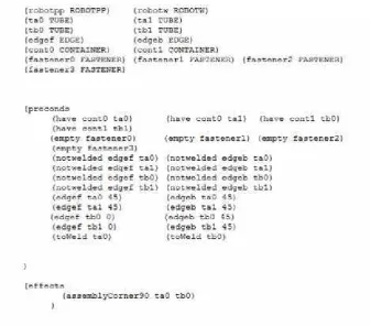
The facts are of three types: objects, description of the domain, and the goal to be reached. First, the objects, correspond to the types of objects that are in the system. Second, the domain description consists in a set of literals that describes the environment or the initial state. Third, the goal consists in a set of literals that describes the final state.
the edge angles of the tubes, tubes to be welded, an empty state of the table fasteners, orientation and direction of fasteners (horizontal/vertical orientation and perpendicular direction), sequential order of the fasteners, equality of the fastener space and the tube length, location of the tubes, and the permission to weld the tubes. In Table 5.2 is shown an example of each type description of the domain. Third, the goal is a set of literals that describes the assembly desirable to reach in base on the facts taken. Table 5.3 shows an example of each goal type and also it is shown the combinations of goal types.
The operators consist in a set of actions that can be applied to the objects to change a state. An operator consists of three parts: parameters, preconditions, and effects. First, the parameters consist of the objects treated. Second, the preconditions are literals that describe the state to accomplish at this moment in order to apply the operator. Third, the effects consist in a set of literals that describe the state after the operator is applied.
In this thesis, the operators, which are shown in Table 5.4, assumed that the workcell contains a welding robot, a pick-and-place robot, an intelligent welding table and a pallet with the objects to joint. The operators developed are :
• First, the operator “pickAndPlace” describes the action of pick an object from the container and place it in the welding table. In Figure 5.2.1 it is shown the sequence of execution of thepickAndPlace operator for the tube called td1, which is in containerct4 and will be placed in the fastenerf0. In the initial state of this example, the tubes are in the container, and the fasteners are empty in the table. In the final state of this example, the tubetd1, which was in the container ct4, is placed in the fastener f0. In Table 5.5 it is shown the state before and after the operator is executed in the environment.
• Second and third, the operators “open” and “close” are high-level commands for the table to open and close the clamps or fasteners.
• Fourth and fifth, the high-level commands: “offsetx” and “offsety” indicate the offset in x-axis and y-axis respectively in a reference to a point in the table.
Table 5.1: Object types
Object Type Description Object name Object photo in real world
ROBOTPP Pick-and-Place Robot robotpp
ROBOTW Welding robot robotw It does not apply
TUBE Tube
ta
tb
tc td EDGE Tube end edgef
edgeb EDGEM Transversal section edgem
of the tube
CONTAINER
Container where are ct1 placed the tubesta
Container where are ct2 placed the tubestb
Container where are ct3 placed the tubestc
Container where are ct4 placed the tubestd
FASTENER
f0 f1 Fasteners to fix f3 the tubes in the table f4 f5 f6
Table 5.2: Domain literals
Literal for Description Example Graphical
describe the world representation
(isHorizontal<f>)
The fastener is located
(isHorizontal f3) in the horizontal direction
of the coordinate plane
(isVertical<f>)
The fastener is located in
(isHorizontal f0) the vertical direction of
the coordinate plane
(isPerpendicular<f1> <f2>)
The directions of the
(isPerpendicular f0 f3) fasteners<f1>and
<f2>are perpendicular, where<f1>is in the vertical direction and
<f2>is in the horizontal
direction
(isNext<f1> <f2> <distance>)
The distance between the
(isNext f4 f3 25.5) fasteners<f1>and<f2>
is the value of<distance>,
also this literal indicates that the fastener<f2>is to the right of the fastener<f1>
(isNextInx<f1> <f2>)
The fastener<f2>is to
(isNextInx f5 f3) the right of the fastener
<f1>in the x-axis of the coordinate plane
(equal<t> <f>) (equal tc0 f0) The tube length<t>is
equal to the space distance of the fastener<f>
(have<ct> <t>) The container<ct> (have ct3 tc0) has the tube<t>
(empty<f>) The fastener<f>is empty (empty f0)
(<edge> <t>0) The edge angle of the (edgef tc0 0) tube<t>is 0◦. (edgem tc0 0)
(<edge> <t>45) (edgeb tc0 45) The edge angle of the
Table 5.2: (Domain literals )
Literal for Description Example Graphical
describe the world representation
(notwelded<edge> <t>)
The tube edges<edge>,
(notwelded edgef tc0) which could be of type: edgef,
edgeb or edgem, are not welded for the tube<t>
(toWeld<t>) Permission to weld the
(toWeld tc0) It does not apply tube<t>
Table 5.4: List of operators
Operator Parameters Preconds Effects
Pick (<r>ROBOTPP) (toWeld<t>) (canWeld)
AndPlace (<t>TUBE) (open<f> <t>) (canor<t>) (<c>CONTAINER) (have<c> <t>) (canox<t>) (<f>FASTENER) (empty<f>) (canoy<t>)
(in<t> <f>) (del have<c> <t>)
(del empty<f>)
open (<f>FASTENER) (open<f> <t>)
(<t>TUBE)
close (<f>FASTENER) (in<t> <f>) (close<f> <t>) (<t>TUBE)
offsetx (<t1>TUBE) (canox<t1>) (offsetx<t1> <d>) (<d>DISTANCE) (canox2<t1>) (del canox<t1>)
(del offsetx<t1>0)
offsety (<t1>TUBE) (canoy<t1>) (offsety<t1> <d>) (<d>DISTANCE) (canoy<t2>) (del canoy<t1>)
(del offsety<t1>0)
welding (<r>ROBOTW) (canWeld) (del canWeld) Corner (<t1>TUBE) (isVertical<f1>) (del notwelded<e1> <t1>)
90 (<t2>TUBE) (isHorizontal<f2>) (del notwelded<e2> <t2>) (<e1>EDGE) (isPerpendicular<f1> (assemblyCorner90<t1>
(<e2>EDGE) <f2>) <t2>)
(<f1>FASTENER) (close<f1> <t1>) (assemblyCorner<t1> <t2>) (<f2>FASTENER) (close<f2> <t2>)
(notwelded<e1> <t1>)
(notwelded<e2> <t2>) (in<t1> <f1>) (in<t2> <f2>) (<e1> <t1>45) (<e2> <t2>45)
(equal<t1> <f1>) (equal<t2> <f2>)
welding (<r>ROBOTW) (canWeld) (del canWeld) Corner (<t1>TUBE) (isVertical<f1>) (del notwelded<e1> <t1>)
90v2 (<t2>TUBE) (isHorizontal<f2>) (del notwelded<e2> <t2>) (<e1>EDGE) (isPerpendicular<f1> (assemblyCorner90<t1>
(<e2>EDGE) <f2>) <t2>)
(<f1>FASTENER) (close<f1> <t1>) (assemblyCorner<t1> <t2>) (<f2>FASTENER) (close<f2> <t2>)
Table 5.4: (List of operators )
Operator Parameters Preconds Effects
(notwelded<e2> <t2>) (in<t1> <f1>)
(in<t2> <f2>) (<e1> <t1>0) (<e2> <t2>0) (equal<t1> <f1>) (equal<t2> <f2>)
welding (<r>ROBOTW) (canWeld) (del canWeld) Corner (<t1>TUBE) (isVertical<f1>) (del notwelded<e1> <t1>)
90ox (<t2>TUBE) (isHorizontal<f2>) (del notwelded<e2> <t2>) (<e1>EDGE) (isVertical<f3>) (assemblyCorner90<t1>
(<e2>EDGE) (offsetx<t1> <d>) <t2>)
(<f3>FASTENER) (isPerpendicular<f1> (assemblyCorner<t1> <t2>) (<f2>FASTENER) <f2>)
(<f1>FASTENER) (isNext<f3> <f1>
(<d>DISTANCE) <d>) (close<f3> <t1>) (close<f2> <t2>) (notwelded<e1> <t1>)
(notwelded<e2> <t2>) (in<t1> <f3>) (in<t2> <f2>)
(<e1> <t1>45) (<e2> <t2>45) (equal<t1> <f3>) (equal<t2> <f2>)
welding (<r>ROBOTW) (canWeld) (del canWeld) Corner (<t1>TUBE) (isVertical<f1>) (del notwelded<e1> <t1>) 90oxv2 (<t2>TUBE) (isHorizontal<f2>) (del notwelded<e2> <t2>) (<e1>EDGE) (isVertical<f3>) (assemblyCorner90<t1>
(<e2>EDGE) (offsetx<t1> <d>) <t2>)
(<f3>FASTENER) (isPerpendicular<f1> (assemblyCorner<t1> <t2>) (<f2>FASTENER) <f2>)
(<f1>FASTENER) (isNext<f3> <f1>
(<d>DISTANCE) <d>) (close<f3> <t1>) (close<f2> <t2>) (notwelded<e1> <t1>) (notwelded<e2> <t2>)
(in<t1> <f3>) (in<t2> <f2>) (<e1> <t1>0)
(<e2> <t2>0) (equal<t1> <f3>) (equal<t2> <f2>)
welding (<r>ROBOTW) (canWeld) (del canWeld)
Corner (<t1>TUBE) (isVertical<f1>) (del notwelded<e1> <t1>) 90oy (<t2>TUBE) (isHorizontal<f2>) (del notwelded<e2> <t2>) (<e1>EDGE) (isHorizontal<f3>) (assemblyCorner90<t1>
(<e2>EDGE) (offsety<t2> <d>) <t2>)
(<f1>FASTENER) (isPerpendicular<f1> (assemblyCorner<t1> <t2>)
(<f3>FASTENER) <f2>) (<f2>FASTENER) (isNext<f3> <f2>
(<d>DISTANCE) <d>)
Table 5.4: (List of operators )
Operator Parameters Preconds Effects
(close<f3> <t2>) (notwelded<e1> <t1>)
(notwelded<e2> <t2>) (in<t1> <f1>) (in<t2> <f3>) (<e1> <t1>45) (<e2> <t2>45)
(equal<t1> <f1>) (equal<t2> <f3>)
welding (<r>ROBOTW) (canWeld) (del canWeld) Corner (<t1>TUBE) (isVertical<f1>) (del notwelded<e1> <t1>) 90oyv2 (<t2>TUBE) (isHorizontal<f2>) (del notwelded<e2> <t2>) (<e1>EDGE) (isHorizontal<f3>) (assemblyCorner90<t1>
(<e2>EDGE) (offsety<t2> <d>) <t2>)
(<f1>FASTENER) (isPerpendicular<f1> (assemblyCorner<t1> <t2>) (<f3>FASTENER) <f2>)
(<f2>FASTENER) (isNext<f3> <f2>
(<d>DISTANCE) <d>) (close<f1> <t1>)
(close<f3> <t2>) (notwelded<e1> <t1>) (notwelded<e2> <t2>)
(in<t1> <f1>) (in<t2> <f3>) (<e1> <t1>0) (<e2> <t2>0) (equal<t1> <f1>)
(equal<t2> <f3>)
welding (<r>ROBOTW) (canWeld) (del canWeld) T90ox (<t1>TUBE) (isVertical<f1>) (del notwelded<e1> <t1>)
(<t2>TUBE) (isHorizontal<f2>) (del notwelded<e2> <t2>) (<e1>EDGE) (isVertical<f3>) (assemblyT90<t1> <t2>) (<e2>EDGEM) (offsetx<t1> <d>) (assemblyT<t1> <t2>) (<f3>FASTENER) (isPerpendicular<f1>
(<f2>FASTENER) <f2>) (<f1>FASTENER) (isNext<f3> <f1>
(<d>DISTANCE) <d>) (close<f3> <t1>) (close<f2> <t2>)
(notwelded<e1> <t1>) (notwelded<e2> <t2>)
(in<t1> <f3>)
(in<t2> <f2>) (<e1> <t1>0) (<e2> <t2>0) (equal<t1> <f3>) (equal<t2> <f2>)
welding (<r>ROBOTW) (canWeld) (del canWeld) T90oy (<t1>TUBE) (isVertical<f1>) (del notwelded<e1> <t1>)
(<t2>TUBE) (isHorizontal<f2>) (del notwelded<e2> <t2>) (<e1>EDGEM) (isHorizontal<f3>) (assemblyT90<t1> <t2>)
(<e2>EDGE) (offsety<t2> <d>) (assemblyT<t1> <t2>) (<f1>FASTENER) (isPerpendicular<f1>
(<f3>FASTENER) <f2>)
Table 5.4: (List of operators )
Operator Parameters Preconds Effects
(<d>DISTANCE) <d>) (close<f1> <t1>)
(close<f3> <t2>) (notwelded<e1> <t1>) (notwelded<e2> <t2>)
(in<t1> <f1>) (in<t2> <f3>)
(<e1> <t1>0) (<e2> <t2>0) (equal<t1> <f1>)
(equal<t2> <f3>)
welding (<r>ROBOTW) (canWeld) (del canWeld) Butt90 (<t1>TUBE) (isHorizontal<f1>) (del notwelded<e1> <t1>)
(<t2>TUBE) (isHorizontal<f2>) (del notwelded<e2> <t2>)
(<e1>EDGE) (isNextInx<f2> <f1>) (assemblyButt90<t1> <t2>) (<e2>EDGE) (close<f1> <t1>) (assemblyButt<t1> <t2>) (<f1>FASTENER) (close<f2> <t2>)
(<f2>FASTENER) (notwelded<e1> <t1>) (notwelded<e2> <t2>)
(in<t1> <f1>) (in<t2> <f2>) (<e1> <t1>0)
(<e2> <t2>0) (equal<t1> <f1>) (equal<t2> <f2>)
Choosing Planner algorithm
Two planners were tested to be part of the system. Both planners use the Graph-plan algorithm. The first Graph-planner tested was the original Graph-planner written in C and compiled in Linux. The second planner is based in the original Graphplan algorithm, but this planner was development in JAVA language and uses PDDL (Problem Domain Definition Language) to write the language used by the planner, also using this new planner is possible to do basic mathematical operations and to use conditional logic in the operators.
Table 5.3: Goal literlas
Goal Literla Description Example Graphical representation (offsety<t> <distance>) The tube<t>will
It does not apply have an offset in y-axis
from other object (offsetx<t> <distance>) The tube<t>will
It does not apply have an offset in x-axis
from other object
(assemblyCorner90<t1> <t2>)
The tubes<t1>and<t2>
(assemblyCorner90 tc0 tc1) form an L-shape, where
<t1>is in the vertical axis and<t2>is in the horizontal axis.
The orientation of the assembly depends if there is any offset in the x-axis or y-axis of a tube.
(assemblyCorner90 tc0 tc1) In the case of an offset in x-axis
(offsetx tc0 25.5) the tube<t1>is moved to the
other tube end of<t2>. In the case of an offset in y-axis the tube<t2>is moved to the other tube end of<t1>.
(assemblyCorner90 tc0 tc1) (offsety tc1 25.5)
(assemblyT90<t1> <t2>)
The tubes<t1>and<t2>
(assemblyT90 td0 td1) form an inverted T-shape,
(offsetx td0 13) if there is an
offset in x-axis. In the case of an
offset in the y-axis, the tubes<t1>and
<t2>form a laying T-shape.
(assemblyT90 td0 td1) In this assembly the tube
(offsety td1 13)
<t1>is in the vertical axis and the tube<t2>
is in the horizontal axis.
(assemblyButt90<t1> <t2>)
The tube ends of the tubes
(assemblyButt90 td0 td1)
<t1>and<t2>
are welded forming a line where<t1>and<t2>
Table 5.5: PickAndPlace operator
World Before PickAndPlace operator After PickAndPlace operator
execution execution
Workcell
Container
Table 5.6: Welding operators
Operator Before Welding operator After Welding operator
name execution execution
weldingCorner90
weldingCorner90v2
weldingCorner90ox
weldingCorner90oxv2
weldingCorner90oy
weldingCorner90oyv2
weldingT90ox
(a) Robot in home point (b) Robot in a safe point (c) Robot picks the tube
(d) Robot in a safe point with tube
(e) Robot in home with tube
(f) Robot in a safe point with tube
(g) Robot places the tube
(h) Robot in a safe point without tube
(i) Robot in home point