México a
de 20.
INSTITUTO TECNOLÓGICO Y DE ESTUDIOS SUPERIORES DE
MONTERREY
PRESENTE.-Por medio de la presente hago constar que soy autor y titular de la obra
denominada".
, en los sucesivo LA OBRA, en virtud de lo cual autorizo a el Instituto
Tecnológico y de Estudios Superiores de Monterrey (EL INSTITUTO) para que
efectúe la divulgación, publicación, comunicación pública, distribución,
distribución pública y reproducción, así como la digitalización de la misma, con
fines académicos o propios al objeto de EL INSTITUTO, dentro del círculo de la
comunidad del Tecnológico de Monterrey.
El Instituto se compromete a respetar en todo momento mi autoría y a
otorgarme el crédito correspondiente en todas las actividades mencionadas
anteriormente de la obra.
De la misma manera, manifiesto que el contenido académico, literario, la
edición y en general cualquier parte de LA OBRA son de mi entera
responsabilidad, por lo que deslindo a EL INSTITUTO por cualquier violación a
los derechos de autor y/o propiedad intelectual y/o cualquier responsabilidad
relacionada con la OBRA que cometa el suscrito frente a terceros.
Biodegradation of the Purgeable Fraction of Diesel Fuel under
Nitrate Reducing Conditions and the Effect of Surfactant Gaele
in Batch and Continuous Upflow Biofilm Reactors-Edición
Única
Title
Biodegradation of the Purgeable Fraction of Diesel Fuel
under Nitrate Reducing Conditions and the Effect of
Surfactant Gaele in Batch and Continuous Upflow Biofilm
Reactors-Edición Única
Authors
Mixtli Campos Pineda
Affiliation
Tecnológico de Monterrey, Campus Monterrey
Issue Date
2010-12-01
Item type
Tesis
Rights
Open Access
Downloaded
18-Jan-2017 15:42:39
INSTITUTO TECNOLÓGICO Y DE ESTUDIOS
SUPERIORES DE MONTERREY
CAMPUS MONTERREY
DIVISIÓN DE INGENIERÍA
Y
ARQUITECTURA
PROGRAMA DE GRADUADOS EN INGENIERIA
BIODEGRADATION OF THE PURGEABLE FRACTION OF DIESEL F U a UNDER NITRATE REDUCING CONDITIONS A N D THE EFFECT OF SURFACTANT GAELE IN BATCH
AND CONTINUOUS UPFLOW BIOFILM REACTORS
PROYECTO DE INVESTIGACIÓN
PRESENTADO
COMO
REQUISITO PARCIAL PARA OPTAR AL TÍTULO DE
MAESTRO EN CIENCIAS CON ESPECIALIDAD EN
SISTEMAS AMBIENTALES
POR:
INSTITUTO TECNOLÓGICO Y DE ESTUDIOS SUPERIORES DE MONTERREY
CAMPUS MONTERREY
DIVISIÓN DE INGENIERÍA Y ARQUITECTURA
PROGRAMA DE GRADUADOS EN INGENIERÍA
BIODEGRADATION OF THE PURGEABLE FRACTION OF DIESEL FUEL
UNDER NITRATE REDUCING CONDITIONS AND THE EFFECT OF
SURFACTANT GAELE IN BATCH AND CONTINUOUS UPFLOW BIOFILM
REACTORS
PROYECTO DE I N V E S T I G A C I Ó N PRESENTADO C O M O REQUISITO PARCIAL PARA OPTAR AL TÍTULO DE MAESTRO EN CIENCIAS C O N ESPECIALIDAD EN SISTEMAS
AMBIENTALES
POR
MIXTLI CAMPOS PINEDA
INSTITUTO TECNOLÓGICO Y DE ESTUDIOS SUPERIORES DE MONTERREY
CAMPUS MONTERREY
DIVISIÓN DE INGENIERÍA Y ARQUITECTURA
P R O G R A M A DE G R A D U A D O S EN INGENIERÍA
Los miembros del c o m i t é de tesis recomendamos que la presente tesis
presentada por MIXTLI CAMPOS PINEDA sea a c e p t a d a como requisito parcial
para obtener el grado a c a d é m i c o de Maestro en Ciencias con especialidad en
Sistemas Ambientales
Comité de tesis:
DR. ALBERTO MENDOZA DOMÍNGUEZ
Director del Programa de Maestría en Sistemas Ambientales
M O N T E R R E Y , N.L
I!
DEDICATORY
Πάτερ ημ ών, ό έν τοις ούρανοΐς
άγιασθήτω τό δνομ ά σου,
έλθέτω ή βασιλεία σου,
γενηθήτω τό θέλημ α σου, ώς έν ουρανώ και έπ'ι γης ·
Τον αρτον ημ ών τόν έπιούσιον δός ήμ ΐν σήμ ερον
Και αφες ήμ ΐν τά όφειλήμ ατα ημ ών,
ώς και ήμ εΐς άφήκαμ εν τοις όφειλέταις ημ ών·
Και μ ή ε'ισενέγκης ήμ ας εις πειρασμ όν,
άλλα ρΟσαι ήμ ας άπό τοΰ πονηρού·
Ό τ ι σοΰ έστιν ή βασιλεία και ή δύναμ ις και ή δόξα εις τούς αιώνας τών αιώνων
ACKNOWLEDGEMENTS
This research was supported under the auspices of SEPCONACYT 82761, CONACYT SNILIC
101753, CONACYT SNI91360 research projects, and under the fund of the Cátedra de
Nanomateriales y Materiales Avanzados from ITESM Campus Monterrey CAT 120.
I highly appreciate Dr. Karim AcunaAskar's advice throughout the course of my research and for
letting me work at the Environmental Bioremediation Research Laboratory. Thank you for your
continuous support and teaching, I had the opportunity to learn about a wide range of subjects,
and to realize the importance of discipline in research.
Dr. Luz Maria Martínez Calderón, for keeping my mind focused on my goals and giving me
perspective in order to continue giving my best. Thanks for everything.
Dr. Marcelo Videa Vargas, for his advice during the project and for letting me work at the
Nanomaterials Laboratory at ITESM. Dr. Roberto Parra Saldivar, for your help and advice during
the project.
Thanks are given to Prof. Dr. Rolando Tijerina Menchaca, M.D., Chairman of the UANL School of
Medicine Department of Microbiology for giving me the opportunity to work at the Regional
Center for the Control of Infectious Diseases and use equipment and facilities to make this work
ABSTRACT
Diesel is a product of the medium fraction of the refining process of petroleum, which
encompasses a mixture of linear and cyclic paraffins, aromatic compounds and hydrocarbons
with chain lengths that range from 10 to 28 carbons. Followed by gasoline, diesel fuel (PEMEX
diesel) is the most sold petroleum fuel with sales of nearly 300,000 tons monthly and a
production of nearly 246,000 barrels per day (SENER; 2010). Contamination of soil and water
bodies with diesel fuel can occur due to spills and leaks from underground tanks, representing a
significant problem since several diesel components are considered carcinogenic and toxic for
the environment (Health Protection Agency UK; 2007). Therefore, it becomes a necessity to
implement methods to promote intrinsic remediation of the impacted sites or to apply
technologies to accelerate cleanup processes through the use of exogenous mechanisms
involving equipment and instrumentation. Biological reactors are widely known for enhancing
the removal of contaminants up to a certain degree, where microbial populations are capable of
cleaving chemical bonds, and therefore modifying chemical structures. Although there are
previous diesel degradation studies with biological reactors (Boopathy; 2000), this work studied
diesel biodegradation with a biofilm reactor under nitratereducing conditions, using volcanic
and alluvial stones as packing medium, thus providing a more costeffective alternative for
bioremediation of impacted sites. In the present project batch and continuous upflow packed
bed reactor (CPR) studies were conducted to evaluate the biodegradation of the purgeable
fraction of diesel fuel under nitratereducing conditions by using both biphasic pseudofirst
order (BPF) and Arvin's kinetic models. The evaluation of the BPF at a diesel concentration of 30
mg/L recorded the highest first phase rate of 0.20 h1
and 82% removal for the whole range of
diesel (WRD) hydrocarbons with GAELE, and was up to 5fold higher than without GAELE in
batch assays. A 6month CPR study recorded BPF rates 0.1750.412 h1
retention times (HRTs) of 1.53.0 hour at diesel concentrations between 50 and 70 mg/L and
showed up to 95.8% WRD removal at the shorter HRT with GAELE. Without GAELE, effluent ORP
ranged below zero and increased above zero with GAELE. The 12month steadystate CPR study
was run at an HRT of 0.5 hour and involved a 3level diesel concentration range: low, medium,
and high, with and without GAELE. At the 3level diesel concentration ranges, with and without
GAELE, the BPF model did not record significant differences on the WRD rate constants. In
addition, for the C10C18 and C20C22 hydrocarbon ranges, the BPF model recorded slight
differences only at the mediumrange diesel concentration when GAELE was added and failed to
record the effect of GAELE at the low and highrange diesel concentrations. In contrast, Arvin's
model recorded an increase on the WRD overall rates of 2.2, 2.3 and 1.5fold higher at the low
, medium and highrange diesel concentrations when GAELE was added. Furthermore, Arvin's
model recorded an increase on the rates of the C10C18 range of 1.2, 3.3 and 2.5fold for the
low, medium and highrange diesel concentrations with the addition of GAELE. Interestingly,
the increase on Arvin's model rates of the C20C22 range recorded 9.6, 1.8 and 1.2fold higher
when GAELE was added to the low, medium and highrange diesel concentrations,
respectively. As for the C10C18, Arvin's maximum utilization rates recorded an increase of 1.8,
1.9 and 2.3fold at the low, medium and highrange diesel concentrations when GAELE was
added to the assays. Noteworthy, the addition of GAELE increased Arvin's maximum utilization
rates of C20C22 by 36.1, 1.4 and 1.8fold for the low, medium and highrange diesel
concentrations, respectively. Among the bacteria identified were the following: Pseudomonas
aeruginosa, Pseudomonas stutzeri, Burkholderia cepacia, Achromobacter xylosoxidans,
Citrobacter freundii and Ralstonia picketti. In batch studies ORP and DO ranged from 126 mV
and 6.9 mg/L at the start of the assays to 130 mV and 0.0 mg/L at the end. In CPR studies ORP
effluent. BOD5 removals ranged 96.173.1% from the lowest to the highest diesel concentrations
without GAELE, and increased from 98.1 to 90.8% with GAELE. On the other hand, COD removals
ranged 92.941.6% from the lowest to the highest diesel concentrations in the absence of
GAELE, and increased from 94.7 to 80.7% in the presence of GAELE. GAELE also contributed to
TABLE OF CONTENTS
DEDICATORY Ill
ACKNOWLEDGEMENTS IV
ABSTRACT V
TABLE OF CONTENTS VIII
INDEX OF FIGURES XI
INDEX OF TABLES XI
CHAPTER I. INTRODUCTION 1
1.1 DIESEL: COMPOSITION AND ENVIRONMENTAL IMPACT 1
1.1.1 Toxicity of diesel components 3
1.1.2 Normativity on Maximum Contaminant Levels (MCLs) of Total Petroleum
Hydrocarbons (TPHs) and on those pertaining to diesel 4
1.2 PROJECT OBJECTIVES 6
1.3 SCIENTIFIC CONTRIBUTION 7
CHAPTER II. THEORETICAL BACKGROUND 9
2.1 BIODEGRADATION 9
2.1.1 Biological reactors 9
2.1.2 Batch reactors 11
2.1.3 Continuous-flow biodegradation 11
2.3 SAMPLE INJECTION METHODS 1 9
2.4 METHOD OF DIESEL QUANTIFICATION 2 0
CHAPTER III. EXPERIMENTAL PROCEDURE 21
3.1 CHEMICALS AND CULTURE CONDITIONS 2 1
3.2 BACTERIAL SEED PREPARATION 2 1
3.3 DESIGN OF BATCH BIOASSAYS 2 2
3.4 STERILIZATION OF SOIL, HETEROTROPHIC PLATE COUNT AND SONICATION 2 3
3.5 DETERMINATION OF ENVIRONMENTAL PARAMETERS AND ANALYSIS OF DIESEL 2 4
3.6 VAPORLIQUID PHASE PARTITION COEFFICIENT CURVE OF DIESEL 2 5
3.7 CONTINUOUSFLOW BIOFILM REACTOR OPERATION 2 6
3.8 ANALYTICAL DETERMINATION DESIGN FOR CONTINUOUSFLOW 2 9
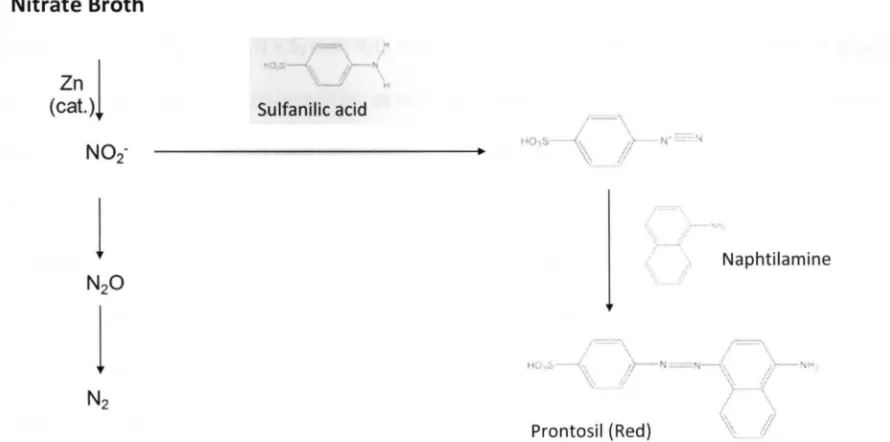
3.9 NITRATE REDUCTION TEST 2 9
3 . 1 0 CRITICAL MICELLE CONCENTRATION ( C M C ) 3 0
3 . 1 1 EVALUATION OF BIPHASIC PSEUDOFIRST ORDER MODEL 3 1
3 . 1 2 EVALUATION OF ARVIN'S MODEL 3 1
3 . 1 3 ISOLATION AND IDENTIFICATION OF DIESELDEGRADING BACTERIA 3 3
3 . 1 4 PREDOMINANCE ASSAYS 3 5
CHAPTER IV. RESULTS AND DISCUSSION 36
4.1 VALIDATION OF THE ANALYTIC METHOD 3 6
4.2 BATCH KINETICS 3 6
4.3 CONTINUOUSFLOW KINETICS AFTER 6 MONTHS OF BIOFILM GROWTH 4 0
4.4 CONTINUOUSFLOW KINETICS AFTER 1 2 MONTHS OF BIOFILM GROWTH 4 5
4.6 BACTERIAL IDENTIFICATION IN CONTINUOUS FLOW ASSAYS 53
4.7 BIOREACTOR INFLUENT AND EFFLUENT B O D / C O D RATIOS 55
4.8 STATISTICAL ANALYSIS FOR ARVIN'S MODEL 57
4.9 STATISTICAL ANALYSIS FOR THE BIPHASIC PSEUDOFIRST ORDER MODEL 59
CHAPTER V. CONCLUSIONS 62
REFERENCES 67
APPENDIX A 76
APPENDIX B 79
APPENDIX C 80
APPENDIX D 81
APPENDIX E 81
INDEX OF FIGURES
Figure 2. Typical chromatogram of diesel fuel 19
Figure 3. Continuous up flow biofilm reactor installed for kinetic assays 28
Figure 6. Biodegradation kinetics of the purgeable fraction of diesel 41
Figure 7. Maximum utilization rates 51
Figure 8. Partial vapor pressures of the purgeable fraction of diesel resulting from substrate
concentrations at biofilm reactor sampling points 53
Figure 10. Example of chromatogram of diesel fuel obtained by purge and trap injection 76
Figure 11. Direct injection of Diesel Range Organics (DRO) 76
Figure 12. Chromatogram of DRO analyzed with purge and trap injection 77
Figure 13. Chromatogram of the direct injection of diesel fuel 77
Figure 14. Calibration curve for the method detection limit of diesel in aqueous samples 78
Figure 15. Calibration curve for the detection limit of diesel in the vapor phase 78
INDEX OF TABLES
Table 1. Diesel composition in mass percentage 2
Table 2. Effects of several diesel components on human health 4
Table 3. Maximum contaminant levels established in the U.S. and Mexico for some chemicals.. 5
Table 4. Mexican norms involving regulatory levels for different types of hydrocarbons, including
diesel 5
Table 5. Maximum Contaminant Levels for hydrocarbon fractions of petroleum 6
Table 6. Different types of biological reactors that have been used for biodegradation 10
Table 8. Types of microbial supports used for biofilm growth. Taken from different sources 13
Table 9. Microaerophilic degradation of the purgeable fraction of diesel in batch assays 38
Table 10. Diesel removal conditions in the biofilm reactor at 6month period of biofilm growth
for various HRTs 43
Table 11. Diesel removal conditions in the biofilm reactor at 12month steadystate maturation
period at a fixed HRT of 0.5 h 49
Table 12. Identification of bacteria and microbial population predominance 55
Table 13. BOD and COD removal percentages at various diesel concentrations 56
Table 14. Twoway ANOVA results for Arvin's overall biodegradation constants 83
Table 15. Twoway ANOVA results for Arvin's biodegradation constants of hydrocarbon chain
length range C10C18 83
Table 16. Twoway ANOVA results for Arvin's biodegradation constants of hydrocarbon chain
length range C20C22 83
Table 17. Twoway ANOVA results for the bipashic pseudofirst order overall biodegradation
constants 84
Table 18. Twoway ANOVA results for the biphasic pseudofirst order constants of hydrocarbon
chain length range C10C18 84
Table 19. Twoway ANOVA results for the biphasic pseudofirst order constants of hydrocarbon
chain length range C20C22 84
Table 20. Twoway ANOVA results for Arvin's overall maximum utilization rate 85
Table 21. Twoway ANOVA results for Arvin's maximum utilization rate of hydrocarbon chain
length range C10C18 85
Table 22. Twoway ANOVA results for Arvin's maximum utilization rate of hydrocarbon chain
CHAPTER I. INTRODUCTION
One of the main causes of water and soil contamination is the release of petroleumderived
hydrocarbons into the environment; particularly, automotive diesel that has higher toxicity than
petroleum in almost every environment. Remediation technologies developed to clean
impacted sites with contaminants coming from fuel diesel include physical and chemical
methods such as filtration and combustion, which has a high demand for energy, and biological
methods, like bioremediation which represents the most costeffective solution. Therefore,
understanding the capabilities of biodegradation under specific conditions becomes necessary
for the design of efficient remediation technologies. Examples of these key conditions that
maximize the efficiency of bioremediation are the type of biological reactor, identification and
selection of contaminant degrading bacteria consortium, the kinetic parameters of pollutant
removal, the oxidative nature of the media and the effect of additives that favor the substrate
availability. The present project focuses on the study of the above mentioned conditions to
biodegrade diesel using a specific biological reactor under nitrate reducing conditions.
The study of biodegradation of diesel requires the knowledge of diesel composition and
the recognition of its toxicity since it plays a fundamental role in understanding the
environmental impact of this source of contamination. All of these concepts and the normativity
established by the environmental protection agencies regardless the permit limits of diesel as
well as the general and specific objectives of the present work will be mentioned in this chapter.
1.1 Diesel: composition and environmental impact
Petroleum derivatives are classified according to petroleum's distillation fraction during the
refining process: the heavy fraction, the middle fraction and is composed by a mixture of
C10C28. The composition of a diesel fuel has been reported by ÁlvarezCuenca et al. (2006), as
shown on Table 1. This composition makes diesel fuel comparable to gasoline; nevertheless,
diesel fuel has a higher proportion of linear and cyclic paraffins, and a much lower presence of
aromatic hydrocarbons. Diesel fuel is composed of hydrocarbons with a number of carbons in
the 10 28 range, resulting in a high heterogeneity. As previously noted, demand of diesel has
increased due to the increment in the number of vehicles that require this fuel. After gasoline,
diesel (PEMEX diesel) is the highest sold fossil fuel, with sales close to the 300,000 metric tons
per month and a production of 246,000 barrels per day in the first quarter of 2010 (SENER).
Table 1. Diesel composition in mass percentage. Edited from ÁlvarezCuenca et al. (2006).
Diesel contamination of sites such as soil or underground water represents a serious problem
due to the toxicity of several components of diesel. Even though diesel has, similarly to gasoline,
a small fraction of a group of hydrocarbons known as BTEX (benzene, toluene, ethylbenzene and
xylene), this fraction has been shown to hace damaging effects to human health (Kao, et al.;
2001). In addition, paraffins and olefins represent most of diesel hydrocarbon composition,
Diesel component Mass %
Paraffins 39.7
Cyclic paraffins 50.8
Alkylbenzenes 3.2
Indanes and tetralines 0.8
Indenes 0.1
Alkylnaphtalenes 1.6
Acenaphtenes and biphenyls 2.2
which cause a decrease on water quality and renders it inadequate for any use (ÁlvarezCuenca
et al.; 2006).
Leaks in underground fuel storage tanks are the main source of the diesel that is present
in underground water (Eriksson & Hallbeck; 2006). Leaks and spills originating from these tanks
represent a great contribution to the availability of petroleum hydrocarbons in the environment.
Furthermore, diesel components are readily transported from soil into underground water
reservours by leaching. Thus, water bodies have a risk of being contaminated by diesel
hydrocarbons, posing a potential risk to human heatlh. The US Environmental Protection Agency
reported in 1990 that around 100,000 leaks from underground petroleum fuel storage tanks
were detected (Britto et al.; 1996). This renders diesel fuel as an environmental contaminant,
which has the potential to pollute great amounts of underground water. Considering that 30%
of the population of the United States uses underground water as source of drinking water
(Hartley et al.; 1999) and that, in the case of Mexico, this number reaches 70% (Morales et al.;
IMP), the problem of diesel contamination of water bodies due leaks and filtrations becomes an
important issue that must be addressed.
1.1.1 Toxicity of diesel components
Diesel components, such as policyclcic aromatic hydrocarbons (PAH), representing 10% of total
diesel components, have been classified as carcinogenic by the Agency of Toxic Substances and
Disease Registry (1995). Furthermore, the USEPA (2009) has identified that several diesel
components have a toxic effect on the central nervous system. Thus, ingestion of disel
contaminated water has the potential to casue from headaches and allucinations, to inhability
The BTEX group corresponds only to nearly less than 5% of diesel components, have high
solubility in water (up to 1,700 mg/L), thus increaseng their potential of being present in water
bodies. Further, these components are widely know for their toxicity and are strictly regulated in
several countries. Benzene has been the component of most interest due to its great
carcinogenic potential, while the other substances present different levels of toxicity. Different
effects on human health caused by some components of diesel are shown in Table 2, according
to the USEPA. In addition, Coulon et al. (2005) have observed that diesel presents a higher
toxicity than crude petroleum in almost every environment, suggesting further studies on the
toxicity of diesel should be conducted, since fewer studies have been published as compared to
those pertaining to the toxicity of gasoline components.
Table 2. Effects of several diesel components on human health. Edited from USEPA (2009).
1.1.2 Normativity on Maximum Contaminant Levels (MCLs) of Total Petroleum
Hydrocarbons (TPHs) and on those pertaining to diesel.
As shown in TABLE 3, there are several MCLs for some of diesel components in water in the US
and Mexico. The US EPA has published the MCL's to regulate BTEX contamination. The
Association for Environmental Health and Safety (2009) has also published recommendations to
regulate contamination by hydrocarbons within the chain lengths C1 0C2 0. In the case of Mexico,
Substance Potencial effect on human health Benzene Anemia, cancer in the form of leukemia Toluene Damage to nervous sistem, kidneys and lungs
federal regulations for hydrocarbons with carbon numbers in the range of 1020 do not exist,
and regulatory levels have been established only for soil.
Table 3. Maximum contaminant levels established in the U.S. and Mexico for some chemicals present in diesel. Edited from USEPA (1997, 2009) and Hartley et al. (1999)
Substance Permissible level in the USA Permissible level in Mexico
(mg/L) (mg/L)
Benzene 0.005 0.01
Toluene 1 0.3
Xylene 10 0.5
Ethylbenzene 0.7 0.7
Cio —
C20 HCs 0.42 Not avaible
[image:21.612.100.528.457.691.2]Table 4 presents Mexican regulations involved in establishing the composition and characteristics of water for different beneficial uses, as well as the MCL's for hydrocarbons in different soils and specifications for their characterization and remediation. A brief description of each norm is presented as well. Table 5 shows the MCL's different petroleum distillation fractions (diesel corresponds to the medium fraction as mentioned above) for each type of soil use.
Table 4. Mexican norms involving regulatory levels for different types of hydrocarbons, including diesel.
Table 5. Maximum Contaminant Levels for hydrocarbon fractions of petroleum according to soil use in Mexico. Edited from DOF Diario Oficial de la Federacion (2003).
It becomes evident that remediating contaminated soil or water bodies is necessary not only to
comply with enforceable environmental regulations and meet maximum contaminant limit
goals, but also to prevent further contamination of water bodies, either groundwater or
downstream the contaminant plumes. In doing so, the quality of water bodies and human
health can be preserved as well. Several remediation techniques exist that can be applied to
remove diesel, among them biodegradation methods offer the most costeffective.
1.2 Project objectives
The main objective of this research is to evaluate the biodegradation kinetic constants of diesel
in batch and continuous upflow biofilm reactors under nitratereducing conditions at different
hydraulic retention times and determine the effect of anionic surfactant GAELE on diesel
removal and biodegradation kinetic rates.
In order to achieve the necessary conditions for the kinetic assays, and to succesfully apply the
kinetic models, it was necessary to accomplish the followig specific objectives:
Hydrocarbon fraction Soil use
(mg/kg dry weight)
Agriculture Residential Industrial
Light 200 200 500
Medium 1,200 1,200 5,000
1. Implement an analytic procedure for the quantification of dieselrange organic (DRO)
hydrocarbons in aqueous samples using gas chromatography.
2. Install and operate a continuous upflow reactor using a mixture of volcanic and alluvial
stones, as microbial support, in order to grow a biofilm adapted to diesel degradation
and confirm nitratereducing capabilities of batch and continuousflow reactors.
3. Isolate and identify Gramnegative bacterial populations adapted to diesel degradation
in batch and continuousflow biofilm reactors, using a bacterial identification
biochemical system with confirmation by DNA extraction.
4. Determine the cell mass concentration in batch and continuousflow reactors in terms
of volatile suspended solids (VSS).
5. Evaluate diesel biodegradation kinetic rate constants under nitratereducing conditions
in batch and continuousflow reactor inoculated with 6 and 12month adaptation
period biofilm.
6. Determine the vapor pressure of the purgeable diesel components according to their
respective concentration in the liquid phase for each bioreactor sampling point in the
presence and absence of sufactant GAELE.
7. Determine the effect of surfactant GAELE on diesel biodegradation.
8. Determine the efficiencey of the reactor on diesel hydrocarbon removal by measuring
COD and BOD5 at three different concentrations with and without GAELE.
1.3 Scientific contribution
The present study evaluated a biphasic kinetic model not previously published for diesel
biodegradation using a batch reactor. This model indicates the capabilities of a batch design to
degrade diesel under nitratereducing conditions. In addition, a continuousflow biofilm reactor
surface area which stimulated an effective biofilm growth and biofilm attachment. Then, the
continuosflow biofilm design allowed the use of short hydraulic retention times, useful for non
recalcitrant substrates.
Two kinetic models, biphasic and Arvin's model, not previously published for diesel degradation
in a continuousflow biofilm reactor were evaluated. A comparison between the kinetic
constants obtained from two different models and their applicability in biofilm performance
analysis. An analysis of the bacterial consortium for each biofilm reactor segment comprising
Gramnegative bacterial identification, biofilm growth determination and biomass calculation, in
terms of VSS, is also presented.
It is noteworthy to add that this study implemented a complete methodology for the evaluation
of the treatability of diesel fuel in aqueous matrix. Factors that become relevant when working
with a multisubstrate mixture such as centroid molar volume, diffusion in the bulk liquid and
into the biofilm, volatilization and secondarysubstrate uptake were taken into consideration.
Therefore, the methodology developed has a high potential for scaling and application in
CHAPTER II. THEORETICAL BACKGROUND
Automotive diesel is a complex mixture of volatile and semivolatile chemical compounds that
include linear and branched hydrocarbons often reported as recalcitrant contaminants of soil
and water bodies. To understand and propose bioremediation actions the fundamental
concepts such as biodegradation, continuous upflow biofilm reactors and gas chromatography
as a technique to quantify diesel are introduced in this chapter.
2.1 Biodegradation
Biodegradation is a process that focuses on the removal of chemical compounds, through its
decomposition or transformation, by using organisms. This process can occur thanks to the
enzymatic capabilities of organisms, allowing metabolization of chemicals and convert them into
biomass, and some other inocuous products such as water and carbon dioxide. This process is
termed bioremediation, and requieres the use of biological reactors.
2.1.1 Biological reactors
Remediation requires an indepth assessment of the physicalchemical properties of
contaminants as well as the characterization of the surrounding environment site to be treated.
This would include either an evaluation on the potential of indigenous biological constituents to
promote intrinsic remediation on the impacted site or applying technologies to accelerate
cleanup processes through exogenous mechanisms involving equipment and instrumentation.
Biological reactors are widely known to enhancing the removal of contaminants up to a certain
degree in batch cultures, where microbial populations are capable of cleaving chemical bonds,
and therefore modifying chemical structures, while growing prior to reach the stationary phase.
Table 6 shows different types of biological reactor that have been used to degrade
hydrocarbons. This work will focus on batch and continuous up flow biofilm reactors for
biodegradation studies.
[image:26.612.108.545.404.639.2]Figure 1. General diagram of a biological reactor. A biological reactor has three important characteristics: type of reactor, microbial support (if used) and type of surfactant (if used).
Table 6. Different types of biological reactors used for biodegradation. Edited from multiple sources
Reactor type Reference
Batch MarquezRocha et al. Water, Air and Soil Pollution., (2001)
Aerobic Submerged Filter (ASF) MorganSagastume et al. Bioresource Technology., (2008)
Sequential Soil Column System Nay et al. Biodegradation, (1999)
Upflow Anaerobic Sludge Blanket Fang et al. J. Environ. Eng. Sci., (1997) Reactor (UASBR)
PseudoContinuous Flow Britto et al. Water, Air and Soil Pollution., (1996) Bioreactor
Microcosmos Mohn et al. So/7 Biology & Biochemistry., (2000)
Fluidized Bed Reactor (FBR) Arrar et al. Biochemical Engineering Journal., (2007)
Continuous Stirred Tank Reactor Geerdink et al. Biodegradation, (1996)
2.1.2 Batch reactors
Batch bioassays are a useful means to depict the response of substrates to a certain microbial
culture. Studies reported have shown that in many instances, however, low degradation rate
constants are obtained regardless the microbial source, either a consortium as in this work, or a
pure culture as in the degradation of diesel by Pseudomonas fluorescens, where a firstorder
kinetic constant of 0.0306 d"1
was reported (Sepic et al., 1996). Therefore, it is necessary to
develop experimental designs to attain highperformance costeffective degradation rates as
posed by continuousflow biofilm assays.
2.1.3 Continuous-flow biodegradation
For continuousflow reactors designed to grow biofilms, substrate concentrations in the bulk
above the minimum concentration to allow growth would maintain a steadystate monolayer
formation which is critical for the operation of biofilm reactors allowing significant thickness of
the microbial film and thus, a suitable substrate flux under steadystate kinetic conditions
(Rittman and McCarty, 1978; 1980a). Due to the lifespan of the biofilm, the thickness can
decline rapidly as the concentration of a single energysupplying substrate decreases in the bulk
liquid (Rittman and McCarty, 1980b), therefore it is important to assess the sustainability, in
particular the maintenance energy rates of a multilayer biofilm that is supplied by complex
mixtures of substrates as well as the possibility to evaluate the maximum utilization rate of
multisubstrate consumption by kinetic configurations deserves to be explored. In addition,
studies on biofilm kinetics have shown that mass transport and molecular diffusivity should be
included in the mathematical models (Hartmann, 1967; Williamson and McCarty, 1976a). It is
predicting the flux of a single ratelimiting substrate (Rittman and McCarty, 1981), further
challenges arise in modeling the kinetics of a complex mixture, where several substrates come
forth not only into the bulk liquid at different concentrations and structural bioavailability, but
also have low volatility which would cause to partition into the vaporliquid phases. Modeling of
secondary utilization holds some constraints, especially for cases where biofilm growth is
established by the utilization of the primary substrate. However, the biofilm mass produced by
the primary substrate can be coupled with the individual concentrations of secondary substrates
to determine their maximum specific substrate utilization rates and their halfvelocity rates in
continuousflow column studies at short and longterm reactor operation (Bouwer and
McCarty, 1985; Williamson and McCarty, 1976b). This work presents a comprehensive study on
up flow biofilm degradation kinetics of long and short chain hydrocarbons at varying diesel
concentrations with and without the presence of a surfactant.
2.2.3.1 Surfactants
Diesel fuel has low solubility in water; therefore, studies to assess the effect of different
surfactants on diesel biodegradation have been man. For example, Franzetti et al. have studied
the effect of Tween and Brij surfactants under different conditions, obtaining and increase in
biodegradation in closed Erlenmeyer flask and in an aerobic stirred batch slurry reactor, but
without using a kinetic model or determining kinetic constants (Franzetti et al. 2008). Several
surfactants used for diesel degradation are shown in Table 7. This work was carried by modeling
the effect of the anionic surfactant GAELE on the biodegradation kinetic rates of diesel, it was
considered to use relatively high initial mass per liter ratios as to reach 24 mg/L and a range of
2.2.3.2 Microbial supports
For the case of biofilms, the use of microbial supports allows for the growth of a microbial
biofilm, required for an effective biodegradation. Supports with high surface area are
recommended, as they can support a greater amount of biomass. Table 8 shows different
supports used for biodegradation of hydrocarbons. High surface area supports, however, have
the risk of washout at short hydraulic retention times (HRT). Therefore, this work uses volcanic
stone (tezontle) and alluvial stone in order to create a packed bed as microbial support, which
allows the use of short HRTs.
Table 8. Types of microbial supports used for biofilm growth. Taken from different sources.
Table 7. Types of surfactants used for diesel biodegradation. Edited from several works.
Surfactant Reference
Rhamnolipids Owsianiak et al. Bioresource Technology., (2009)
Surfactin Whang et al. Journal of Hazardous Materials, (2008)
Tween (sorbitan derivatives) Franzetti et al. Journal of Hazardous Materials., (2008)
Brij (polialkyl ethoxylates) Franzetti et al. Journal of Hazardous Materials., (2008)
Microbial supports Reference
Activated carbon AlvarezCuenca et al. Bioprocess Biosyst. Eng., (2006)
Soil (sand) Nay et al. Biodegradation, (1999)
Volcanic stone MorganSagastume et al. Bioresource Technology., (2008)
No support MarquezRocha et al. Water, Air and Soil Pollution., (2001)
2.2.3.3 Extraction of volatile and semivolatile hydrocarbons
Automotive diesel is a complex mixture of volatile and semivolatile hydrocarbons. Semivolatile
hydrocarbons are not readily extracted by the purge and trap sample concentrator system, not
injection into the gas chromatograph (GC). Therefore, a sound approach would presume the
extraction of the semivolatile fraction of diesel in aqueous samples by using a liquidliquid
extraction procedure with an organic solvent followed by sample concentration. However, a
liquidliquid extraction procedure would involve injecting samples directly into the GC injector.
In our case this imposes a burden on two sides. On the one side, the analysis of diesel as a
substrate by direct injection would increase the method detection limit (MDL) and therefore the
minimum detectable mass in the liquid samples would rise. We found the MDL of diesel in liquid
samples to be at 8.4 mg/L when using hexane as the organic solvent. On the other side,
concentrations near the MDL supplied into our laboratoryscale bioreactor would impose an
extremely high metabolic stress to the biofilm microbial communities as a result of exceeding
reactor design capabilities. In addition, the partition of volatile components of diesel into the
vapor phase has to be taken into consideration, in order to assess the potential of these
components for increasing vapor pressure and thus affecting biological reactor design.
2.2.3.4 Vaporliquid phase thermodynamics
An introductory approach to the complexity of the vaporliquid phase equilibrium involved with
a solution of small amounts of diesel in water would need to consider the system as an ideal
dilute solution, where the vapor pressures of diesel and water play an important role. For the
water as the solvent, its contribution to the total vapor pressure would follow Raoult's law with
a linear relation where the slope is given by the vapor pressure of water in its pure form.
Although diesel is a complex mixture of hydrophobic components, it would be desirable to
picture the whole mixture as a single component for the purpose of calculating the mass of
diesel that would escape from the liquid into the vapor phase and which may not be available
total vapor pressure of the solution would follow Henry's law with a linear relation where the
slope is given by the Henry's law constant (H) as a function of ydfd (Sedlbauer et. al., 2002),
where yd is the activity coefficient. For hydrocarbons that are sparingly soluble in water yd can
be replaced by its value at saturation solubility in water (yd*), which is also given by the
reciprocal of the solute molar fraction at the saturation point (l/xd*), therefore H=/d/xd*. Based
on the reported solubility of diesel in water, ranging 0.2 5 mg/L (UNEP, 1996), the molar
fraction of diesel (MW = 233.3 g/mole) at the saturation point would range from 1.54 x 10"8
to
3.86 x 10"7
. In this paper, the initial mass per liter ratio used for the batch kinetics was nearly 6
times whereas for the continuousflow experiments ranged 10 224 times the solubility. These
initial diesel concentrations would give rise to molar fractions of 1.85 x 10"6
for the batch kinetics
and 2.46 x 1 0s
1.96 x 10"4
for the continuousflow assays. Although these molar fractions were
higher than the saturation solubility, a vigorous mixing as well as micellization may have
enhanced homogeneity to assume dilute solution conditions. With this consideration, a mass
balance evaluation of substrate throughout of the bioiflm reactor can be constructed, in order
to assess the phenomena occurring during biodegradation.
2.2.3.5 Mass balance throughout the continuousflow biofilm reactor
It can be assumed that, at the influent point of the biofilm reactor, the constituents of diesel
would partition into both vapor and liquid phases and that, throughout the biofilm, the mass of
those constituents that make up diesel a whole substrate may split into the removed and non
removed fractions of the substrate between biofilm sampling points. The removed diesel
fraction of the substrate as a whole may contain mass substrate from both the vapor and liquid
phases. In addition, for the particular case of hydrocarbons that are sparingly soluble in water
lower segments of the reactor biofilm would partition into the vapor phase that would flow
upwards through upper segments of the reactor. In contrast, the remaining fractions of the
substrate in the liquid phase may be uptaken by the biota between upper and lower biofilm
segments of the reactor. The fractions of the substrate in the vapor phase flowing upwards
through the reactor can either be degraded or continue flowing free by convective movement
through upper biofilm segments in the reactor. It can also be assumed that the total vapor
phase of the substrate found at the headspace, and which would ultimately be released at the
effluent sampling point, could be originated from: a) the nondegraded vapor mass of the
substrate at the influent and b) the vapor mass coming off from the nonremoved mass fraction
of the substrate in the liquid phase between lower and upper reactor biofilm segments. For the
equations, two assumptions can be undertaken. A mass balance simulation might consider the
upflow of the substrate constituents following a semicompartmentalized model of removal
segments between the column sampling points. Other assumption would bring forward the
inference that at the effluent headspace, under steadystate conditions, at any hydraulic
retention time, keeping the pressure constant, the change of substrate removal in the vapor
phase versus time equals zero. Thus, at headspace: (dSr/dt)P =0. At the reactor entrance point,
the total influent substrate concentration would partition into the liquid and vapor phases as
follows:
The difference of substrate concentrations between upper and lower sampling points would
$n - (S„!.u Sn-\Lu ) +
(SnLr Sn~U.r ) + nViu ~ ^n-Wiu )
+ nV
lr ~ ^n-Wir ) + i^nVu ~ S„-\Vu ) +
(S
nVr- S
n_
m. )
At the effluent vapor chamber headspace sampling point, the total concentration of substrate in
the vapor phase would be given by the following expression:
Where:
S= Substrate concentration
n = number of sampling point
S t h v u = Substrate concentration in the unremoved fraction of vapor phase at headspace
Sgviu = Substrate concentration of the fraction of vapor phase released from the influent
point that freely reached the headspace.
S8 V u = Substrate concentration of the unremoved vapor phase residuals released by the
last biofilm segment.
T, = total substrate concentration at the influent
Vi r = removed fraction of vapor phase released from the influent point
Vi u = unremoved fraction of vapor phase released from the influent point flowing free
throughout the reactor
Lr = removed fraction of liquid phase between sampling points
Vr = removed fraction of the vapor phase released by the liquid phase flowing upwards
through the reactor.
Lu = unremoved fraction of liquid phase between sampling points
2.2 Use of gas chromatography to quantify diesel
Different methods of diesel hydrocarbon quantification exist. Nevertheless, as diesel
components have different properties, chromatography methos present a simple and precise
alternative to quantify diesel hydrocarbons with high leves of precission and efficiency. Due to
the nature of chromatographic analysis, diesel components can be identified individually in such
a way that an indiviual analysis of components or hydrogarbon chain length ranges or an
analysis of diesel as a whole can be performed (Pavlova & Iranova; 2003). As for the case of gas
chromatography, there exist different mechanisms to detect diesel components once separated.
Among the different types of detectors, the ones used for detection of diesel hydrocarbons are
mass spectrometry (GCMS) and flame ionization detection (GCFID) (Pavlova & Iranova; 2003).
Even though mass spectrometry detection offers a high detection level, flame ionizaiton
detection provides a less expensive alternative, while providing an efficient quatitative analysis
in a wide range of concentrations. Figure 2 shows a characteristic chromatogram for diesel
(Sepic et al.; 1996). Peaks corresponding to paraffins are more notorious, as they comprehend a
higher mass percentage, their retention time varyng according to their size. Depending on the
chromatographic parameters used a bump may show, indicating an unresolved hydrocarbon
Figure 2. Typical chromatogram of diesel fuel. The numbered peaks represent several linear hydrocarbons, while the bump corresponds to an unresolved hydrocarbon mixture. Edited from Sepic et al. (1996).
2.3 Sample injection methods
There are two methods for sample injection, direct injection and purge and trap injection. Direct
injection methods consist on taking a diesel sample, being it in the liquid or vapor phase, and
injecting it directly into the gas cromatograph. In contrast, the purge and trap method consists
on injecting an aqueous diesel sample in a container that is purged with an inert gas for a set
time, purging the gaseous phase with the volatile components from the sample. This phase is
then adsorbed on a trap, desorbing later at a wide range of temperatures in order to
concentrate the sample and transfer the analytes to the chromatograph capillary column
(Grindstaff, Guia Tecnica Restek).
The use of a purge and trap system enhances the detection of purgeable diesel components
(Grindstaff, Guia Tecnica Restek), but hinders the detection of non purgeable diesel components
due to the fact that nonvolatile components will no be purged and thus, will not be shown on
the chromatogram. Due to the fact that it is expected the decline of some chromatogram peaks
and the appearance of some other peaks (which could represente the production of
intermediate metabolites), a method that increases precision and enhances the detection limit
of diesel components is preferred, in order to concentrate samples and inject them effciently.
2.4 Method of diesel quantification
While analysis and quantification of single substrates with chromatography methods require
peak identificaction, diesel fuel comprises a wide range of components which have different
retention times and cannot be fully resolved. Therefore, USEPA recommends quantifying diesel
fuel as a sum of areas in a retention time range defined for dieselrange organics. The end of the
area integration range is defined as the retention time when the surrogate oterphenyl appears.
As diesel fuel is the complex sustrate evaluatd in this work, a calibration curve will be
constructed applying EPA's Method 8015B using a gas chromatograph with detection by flame
ionization (GCFID) to perform the quatitative analysis of diesel hydrocarbons in order to obtain
their biodegradation profiles. A purge and trap concentrator will be used for sampling injection
CHAPTER III. EXPERIMENTAL PROCEDURE
3.1 Chemicals and culture conditions
Chemicals, including glycolic acid ethoxylate lauryl ether (GAELE, an anionic surfactant), diesel
range organics (DRO) calibration standard, equilibrated phenol, Triton X100, EDTA,
Tris(hydroxymethyl) aminoethane (Tris), sodium dodecyl sulfate (SDS), absolute ethanol,
chloroformisoamyl alcohol (24:1) and pancreatic ribonuclease (RNase A) were purchased from
SigmaAldrich (Mexico) and were above 98% purity. Diesel was purchased from a local diesel
station. Deionized water from a MilliQ purification system (Millipore, USA) was used in
preparing samples. The TSNT lysis buffer was prepared by diluting the following mixture to 1 L:
a) 500 mL of water with 20 mL of Triton X100, b) 100 mL of 10% (w/v) SDS, c) 20 mL of 5 M
NaCI, d) 5 mL of 2 M TrisHCI at pH 8 and e) 2 mL of 0.5 M EDTA at pH 8. Mineral medium I
(MMI) prepared according to AcunaAskar et al., (2006) was used to maintain the growth of a
bacterial consortium fed with diesel. Mineral medium II (MMII) was prepared to resuspend the
bacterial cells after centrifugation and had the following composition (in g/L): KH2P04, 2;
NH4NO3, 0.5; MgCI2, 0.5; NaC2H302, 1.5; NaN03, 1; glycerol, 0.5; K2HP04, 3.5; trace nutrient stock
solution (in mL/L), 1 (Criddle et al., 1990). The initial pH of MMII was 7.07.5. MMII was used for
batch and continuousflow biofilm experimental assays. Nitrate reducing conditions were tested
by using the Nitrate Reduction Test Kit provided by Fluka (SigmaAldrich Chemie GmbH).
3.2 Bacterial seed preparation
The bacterial consortium used as seed inoculums for both the batch and continuousflow
experimental bioassays was originally obtained from a petrochemical refinery wastewater
flowrate of 30 mL/s ± 5mL/s, and has been fed with 200 mg/L of diesel three times a week for
five years, followed by weekly renewals of the culture medium and biomass detention time of
30 days. Acclimatization conditions include temperature 1826°C, dissolved oxygen (DO) 0.51.2
mg/L, oxidationreduction potential (ORP) 320 to 250 mv and pH 6.97.8. Culture conditions
allowed the bacterial consortium to reach 1,360 mg/L as volatile suspended solids (VSS). VSS
determination followed the Standard Method 2540 E (Standard Methods, 1998). For the batch
assay kinetics design, a total volume of 540 mL of mixed liquor was taken from the bacterial
acclimatization reactor using 12 centrifuge tubes filled up to 45 mL each. The acclimatized
consortium was precipitated in a centrifuge (Beckman Instruments, Inc., Palo Alto, CA), model
Allegra X22R at 3,041 x g at 259
C for 7 minutes. The bacterial cells were resuspended in two 50
mL centrifuge tubes with 35 mL of MMII to reach a VSS of 3,370 mg/L in each concentrate.
3.3 Design of batch bioassays
The substrate mineral medium (SMM) of the batch experimental bioassays was made up of 50
mL of MMII and the addition of 10 u± of diesel into 122mL amberglass crimpsealed bottles
(Wheaton Science Products, Millville, NJ). A 2mL inoculum from the concentrated bacterial cells
was added to S M M to reach 130 mg/L VSS. Because of the density of the diesel used in this
study, 0.84 g/mL, an amount of 8.4 mg of diesel would be expected to partition into both the
liquid and vapor phases. However, samples were mixed for 3 minutes to obtain uniform diesel
concentration causing volatile losses at the start of the kinetics. Further chromatographic
analysis and the use of the vaporliquid phase partition coefficient curve as described below,
for the mass balance, revealed that an amount of nearly 30 mg/L in the liquid phase was the
initial diesel concentration in the batch kinetic studies. Controls with only SMM and three sets of
contained SMM, 130 mg/L VSS of inoculum and 5.5% sterilized soil (SS). Set 3 contained SMM,
130 mg/L VSS of inoculum and 25 mg/L GAELE. Based on the advantages attained by increasing
effective solubility (Volkering et al., 1995), and stimulating suitable intermolecular forces at the
interface to facilitate substrate dissolution rate (Grimberg et al., 1996), the amount of GAELE
added to experimental bioassays was slightly below the critical micelle concentration (CMC).
Samples and controls were shaken at 7 x g at 28305C, using a Labline oscillating incubator
shaker (Barnstead International, Dubuque, IA). The diesel mass was monitored in the liquid
phase for 288 hours at different times from 0, 24, 48, 72, 144 and 288 hours. The diesel in the
vapor phase was obtained by extrapolation from the vaporliquid phase coefficient partition
curve. At the end of the kinetics, to obtain the overall degradation percentage, the diesel left in
both liquid and vapor phases was summed up and the total was subtracted from the initial mass
added at the start of the experiment. The mass balance revealed that the decrease of diesel in
the vapor phase showed a constant relation with the consumption of diesel in the liquid phase,
suggesting that phase equilibrium kept constant throughout the kinetics. For quality control
purposes and to achieve repeatability on data, the experimental bioassays were run by triplicate
at different dates to evaluate the reproducibility of diesel biodegradation kinetics.
3.4 Sterilization of soil, heterotrophic plate count and sonication
A set of threegram samples of soil sieved through mesh 3 mm were wrapped in aluminum foil
and sterilized following three sterilization cycles in an autoclave (Pelton & Crane CO., Charlotte,
NC.) model MC. The number of bacteria was counted by using a Quebec colony counter
(American Optical, Buffalo, NY), model 3325, and reported as colonyforming units per millilitre
of original solution (CFU/mL). Soil samples were considered sterile at a maximum of 5 CFU/mL in
sample preparation and for estimating the number of heterotrophic bacteria. A Branson Sonifier
250 (Branson Ultrasonics, Co., Danbury, CT) sonicator was used and programmed for each
amber serum bottle at two cycles of two minutes each at 80% duty cycle. USEPA method 3550
was used to extract potential diesel trapped in cell materials.
3.5 Determination of environmental parameters and analysis of diesel
The pH and the ORP were measured with a pH probe HI 1618D and an ORP probe HI 3620D
connected to a Hanna HI 98150 microprocessor logging pH/ORP meter. A Hanna HI 9143
microprocessor meter was used to measure DO. The pH, ORP and DO probes were calibrated
on a daily basis. Diesel was analyzed by a Varian 3400 GC/FID chromatograph following standard
procedures with some modifications according to USEPA, (1996). A Petrocol™ (Supelco,
Bellefonte, PA) 100m x 0.25mm ID x 0.5u.m film DH fused silica GC capillary column was used.
The oven temperature started at 709
C and held for 1 min, ramped to 120°C at 2°C/min, held for
5 min, then ramped to 140°C at 3°C/min and held for 3 min, then ramped to 180°C at 2°C/min
and held for 3 min; finally, ramped to 210°C at 50°C/min and held for 5.74 min. The oven
temperature program allowed for both separation of the peaks of diesel components and
avoidance of chromatogram bump formation. The injector was set up at a split ratio of 1:50,
with a split flow of 100 mL/min, at a column flow of 2 mL/min, and its temperature was set up
isothermal at 220°C. Detector conditions included both attenuation and range at 8 and 12,
respectively. Detector temperature was set isothermal at 300°C. A volume of 5 mL of liquid and
vapor (headspace) samples were placed in the purge vessel of a Tekmar* (Cincinati, OH) model
LSC 2000 purge and trap concentrator by using a SGE 10mL gastight syringe (Australia). Liquid
and vapor samples were purged with nitrogen at 80°C for 10 min and desorbed at 225°C for 4
protocol, which included accuracy, precision, specificity, selectivity, method detection limit
(MDL), linearity and robustness testing for the purgeable fraction of diesel was followed
(Bliesner, 2006). Substrate calibration curve of known standard concentrations was based on
fresh commercial diesel. The DRO standard kit was used to assess the degradation of
hydrocarbon chain length segments. Both linear regression and correlation analysis techniques
were employed to draw the standardized calibration curves and effect sample analysis
calculations as well (Daniel, 2006).
3.6 Vapor-liquid phase partition coefficient curve of diesel
To obtain the diesel mass balance that would partition into the vapor and liquid phases in the
batch assays, an experimental vaporliquid phase partition coefficient was obtained. Two sets of
samples were prepared at 25°C by pouring 61 mL of milliQ water with a calibrated burette into
122mL amberglass crimpsealed bottles (Wheaton Science Products, Millville, NJ) and adding
known volumes of diesel with either a 10ui SGE microsyringe or a 100p.L Hamilton
microsyringe (Reno, NV). The total diesel mass added to the bottles was calculated by using the
density of diesel (0.84 g/mL). The two sets contained eleven different quantities of known
amounts of total diesel mass ranging from 0.84 to 20 mg. The total mass of diesel supplied at
the start of the batch assays and monitored throughout the kinetics fell within the range of
diesel mass added. One set of samples was used to analyze diesel in the liquid phase and the
other set to analyze it in the vapor phase. Three charts were plotted with the data from the GC
areas obtained from the liquid and vapor samples. The first chart was plotted with the total
diesel mass added to the bottles vs. the GC areas of the liquid phase samples. The second chart
was plotted with the total diesel mass added to the bottles vs. the GC areas of the vapor phase
slope value obtained from the third chart was used to calculate the experimental vaporliquid
phase partition coefficient of diesel in batch assays. Based on a closed system model used on
the batch bioassays, a practical method detection limit of diesel in the vapor phase (MDLfsel
)
was calculated according to [AVn '{AVn + A,n)] (Mn /Vril), where AVn is the GC area of the 5mL
vapor phase standards, Aln is the GC area of the 5mL liquid phase standards, n is each sample
of two sets of eleven standards analyzed for either the vapor or liquid phases, Mn is the total
mass of diesel added to each standard and VVn is the headspace volume, which was fixed at 61
mL for the eleven vaporphase standards. A chart with the GC area of each vapor phase
standard on the x axis and the standard concentration in the vapor phase on the y axis was
plotted. The extrapolation of the yintercept was taken as the practical {MDLd
ySel
) of the vapor
phase standard curve. The practical (MDL?yesel
) of the diesel purgeable fraction in the vapor
phase was calculated as 4.5 mg/L.
3.7 Continuous-flow biofilm reactor operation
An upflow glasscolumn reactor of 5 cm of inner diameter and 53.34 cm high was used in this
study. Eight sampling points, including influent and effluent, separately distributed every 7.62
cm from each other rendered seven continuous biofilm segment units from the bottom to the
top of the reactor. At the upper end a vapor chamber was connected to keep substrate vapors
confined and in contact with Orbo™ (Supelco, Bellefonte, PA) activated carbon tubes to monitor
volatilization losses in the offgas. Peristaltic pumps at flowrates of nearly 3.2, 6.5 and 20
mL/min were used to feed the influent into the reactor for the HRTs of 3, 1.5 and 0.5 h,