UNIVERSIDAD DE VALLADOLID
ESCUELA DE INGENIERIAS INDUSTRIALES
Grado en Ingeniería Química
Condensación aldólica catalizada por
nanofibras aminadas de sílice electrohiladas
Autor:
Rubio Almazán, Cristina
Responsable de Intercambio en la Uva
Bolado Rodríguez, Silvia
Valladolid, octubre de 2018.
TFG REALIZADO EN PROGRAMA DE INTERCAMBIO
TÍTULO: Aldol condensation catalysed by electrospun aminated silica nanofibres
ALUMNO: Cristina Rubio Almazán
FECHA: 27 de junio de 2018
CENTRO: Laboratory for chemical technology. Universiteit Gent
CONFIDENTIAL UP TO AND INCLUDING 12/31/9999 – DO NOT COPY, DISTRIBUTE OR MAKE PUBLIC IN ANY WAY
Aldol condensation catalysed by electrospun
aminated silica nanofibres
Cristina Rubio Almazán
Supervisors: Prof. dr. ir. Karen De Clerck, Prof. dr. ir. Joris Thybaut,
Prof. dr. Klaartje De Buysser
Counsellors: Eva Loccufier, Anton De Vylder
Dissertation submitted in order to obtain the academic Degree of
Chemical Engineering
Faculty of Engineering and Architecture
i
Confidentiality notice
This master dissertation contains confidential information and/or confidential research results proprietary to Ghent University. It is strictly forbidden to publish, cite or make public in any way this master dissertation or any part thereof without the express written permission of Ghent University. Under no circumstance this master dissertation may be communicated to or put at disposal of third parties. Photocopying or duplicating it in any other way is strictly prohibited. Disregarding the confidential nature of this master dissertation may cause irremediable damage to Ghent University.
The stipulations above are in force until the embargo date 12/31/9999.
Cristina Rubio Almazán
ii
Acknowledgement
These words are to thank everybody who has made this thesis possible.
First, I would like to thank Prof. dr. ir. Karen De Clerck, Prof. dr. Klaartje De Buysser and Prof. dr. ir. Joris Thybaut for giving me the opportunity to join the research of such an interesting topic. Thank you for all the feedback and the guidance in the development of this work.
Thank you, Eva and Anton, for the excellent guidance, understanding and words of encouragement towards the many surprises that I have encountered. It was a great pleasure to have you both as my mentors.
To my Erasmus Promotor Silvia Bolado Rodríguez and to my Erasmus Coordinator Raúl Muñoz Torre, for all their effort, many thanks.
Many thanks as well to the fellow students and staff in the LCT, they made every day unique.
Thank you to my Erasmus friends Giulia, Alex, Jesús, Sara and Giorgia for all the support in the long days, it is a pleasure to welcome you in my life.
Thank you to my friends from home for the long distance support that you have offered me. Thank you specially Manuel, Marina, Carmen and Blanca for accompanying me in this journey.
Finally, I would like to express my gratitude to my family for giving everything to make me reach my objectives, specially to my parents, Olga and Juan Miguel. Thank you Ali for all the encouraging, supporting and inspiring words.
iii
Copyright notice
The author gives permission to make this master dissertation available for consultation and to copy parts of this master dissertation for personal use. In the case of any other use, the confidentiality and copyright terms have to be respected, in particular with regard to the obligation to state expressly the source when quoting results from this master dissertation.
Cristina Rubio Almazán
iv
Aldol condensation catalysed by electrospun aminated
silica nanofibres
By Cristina Rubio
Master dissertation submitted in order to obtain the academic Degree of Chemical Engineering
Academic year: 2017-2018
Supervisors: Prof. dr. ir. Karen De Clerck, Prof. dr. Klaartje De Buysser
Prof. ir. Joris Thybaut
Counsellors: Anton De Vylder and Eva Loccufier
Faculty of Engineering and Architecture Ghent University
Overwiew
Summary
This thesis covers the fabrication, functionalisation and testing of electrospun aminated silica nanofibres. An introduction and literature study in aldol condensation, sol-gel science, electrospinning, functionalisation and catalytic activity is given in chapter 1. The development of the different functionalisation methods, post-functionalisation, direct synthesis and coaxial electrospinning is studied in chapters 3, 4 and 5 respectively. The membrane testing in batch and continuous reactors is covered in chapters 6 and 7.
Key words
v
Aldol condensation catalysed by electrospun
aminated silica nanofibres
Cristina Rubio Almazán
Supervisors: Karen De Clerck, Joris Thybaut, Klaartje De Buysser
Coach: Eva Loccufier, Anton De Vylder
Abstract- This article studies the production, functionalisation
and testing of electrospun aminated silica nanofibres. Before functionalisation, silica membranes allow a thermal treatment to improve the physical resistance of the membranes. Three different functionalisation methods are developed, of which only one, post condensation, shows successful grafting of the functionalities to the silica support. The testing in batch reactor shows that the best catalytic performance is obtained with non heat treated membranes, which present a TOF of 2,09·10-4 s-1, which is of the
same order of the TOF for mesoporous silica with the same loading, 7,78·10-4 s-1.
Keywords- Electrospinning, sol-gel, silica, nanofibres, aldol condensation, heterogeneous catalysis, TEOS, APTES, MAPTMS.
I. INTRODUCTION
Aldol condensation reactions are important in modern petrochemical industry, specially pharmaceutical, as they are one of the reactions that create C-C bonds [1]. This application has made aldol condensation a target for catalyst design, having various catalysts been developed to avoid the strong bases that are being used nowadays, such as NaOH or KOH, and with the objective of achieving a greener industry [2][3]. In an attempt to obtain more sustainable processes, heterogeneous catalysis is studied [4], given that this catalysts are easier to separate from the reaction mixture. The main goal of heterogeneous catalyst researchers is to obtain a catalytic performance as good as, or superior to the one of homogeneous catalysts.
Electrospun silica membranes are a good option for catalyst research due to their high surface area, high porosity (90%) and large pore size (50 to 500 nm)[5]. As silica is a ceramic material, electrospun silica membranes present the physical and chemical resistance, hardness and inertia proper of these materials. Amine functions are added to the silica support, as together they cooperatively catalyse the aldol condensation due to an interaction between the reactants and the surface silanol groups, which creates more active intermediates, increasing the catalytic performance of the amines [6][7] .
Electrospinning produces thin, long fibres by applying a high voltage between the tip of a nozzle and a collector plate. The nozzle is connected to a syringe that contains a solution, typically a polymer, which is made by long molecule chains that can be stretched to form the nanofibres. New materials are being researched to electrospin, such as ceramic materials[8], [9]. The nanofibre is created when the surface tension of the drop in the tip of the nozzle is overcome by the coulombic and electrostatic forces of the electric field, and a jet is ejected towards the collector.
The functionalisation of the membrane is the covalent grafting of the amine functionalities onto the surface. There are
various methods of incorporating functionalities to a membrane; direct synthesis adds the functionalities to the solution before electrospinning [10], post functionalisation incorporates the amines after electrospinning [7] and with coaxial electrospinning the amines are added while electrospinning [11].
II. FUNCTIONALISATION
TEOS (tetraethoxysilane) is combined with ethanol, water and hydrochloric acid in a beaker in the ratios 1:2:2:0,01. The mixture is heated up at 80ºC and hydrolysis and condensation reactions take place, increasing the viscosity of the mixture as the TEOS molecules crosslink forming the long chains of a sol-gel solution.
A. Direct synthesis
In the case of direct synthesis, the amine functionalities are incorporated to the electrospinning mixture. As the target loading for the membrane is 0,5 mmol amine/ g catalyst, the ratios for TEOS:Amine is 1:0,1. Functionalised membranes with lower amine loadings than 0,01 are homogeneously electrospun. However, for higher amine loadings there has not been found any spinnable solution. The objective of the work is the functionalisation of the membranes with secondary amine precursors (MAPTMS, methylaminopropyl-trimetoxysilane), as they are more reactive than the primary amine precursors (APTES, aminopropyltrietoxysilane); in direct synthesis research, both precursors were tried. However, MAPTMS solutions presented sudden gelation than impeded the viscosity tuning needed for electrospinning and APTS solutions presented precipitation before increasing the viscosity.
B. Coaxial electrospinning
vi Figure 1. ATR-FTIR analysis of coaxially electrospun membranes
C. Post functionalisation
In post-functionalisation, TEOS membranes are electrospun and subjected to heat treatments at 400ºC and 800ºC in a high temperature furnace for two hours, including the heating phase at a rate of 10ºC/min. The heat treatment on the membrane modifies its hydrophobicity. The water repellent ethyl groups are hydrolised with time into silanol groups by the air moisture, making the membrane hydrophilic, and then the silanol groups are eliminated with the heat treatment, making the nanofibrous structure hydrophobe, but maintaining the membrane hydrophilic due to the capillarity effect on the pores. The heat treatment on the membrane improves its physical resistance to the functionalisations that will be performed later, because of the elimination of the silanol groups.
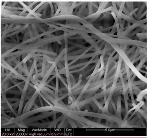
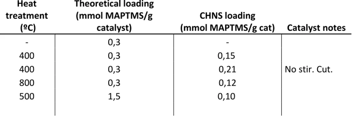
The membrane is functionalised with a secondary amine precursor, MAPTMS (methylaminopropyltriethoxysilane) to reach a target loading of 0,3 mmol MAPTMS/ g catalyst. The functionalisation is carried out in a stirred and unstirred setup, with toluene as a solvent at 110ºC for 24 hours. It is observed that the membrane is damaged by the stirring process, SEM images of the membrane after the functionalisation show that the nanofibrous structure is maintained, see Figure 2. CHNS elemental analysis was performed on the differently post functionalised samples, however this method did not present conclusive results, as non functionalised membranes presented higher nitrogen content than functionalised ones. The amine loading was calculated with the carbon content from the CHNS results. These results conclude that the higher loading was obtained in the untreated membrane, due to its higher silanol number. The temperature in the heat treatment does not influence the loading, as the hydrophilicity of the resultant membrane is mostly due to the removal of the ethyl groups and not to the number of surface silanols. The membranes that were functionalized without stirring present higher amine loadings, as the clumping of the stirred membranes around the magnet reduces the contact with the amine solution, and therefore reduces the loading in stirred membranes.
Figure 2. SEM image of functionalised membrane
III. REACTION TESTING
A. Batch reactor
The CHNS elemental analysis results were not reliable to calculate the amine loading, so the TOF (turn over frequency) of the reactions was calculated using the target loading of each membrane, see Table 1.
Table 1. TOF of post functionalised membranes in batch reactor
Heat treatment (ºC) TOF (s-1) Catalyst notes
- 2,09E-04
400 -
400 3,52E-05 No stir. No cut. 400 2,99E-05 No stir. Cut.
800 2,99E-05
The best TOF is obtained with the membrane that has not been heat-treated. The experiment with the 400ºC membrane and stirred functionalisation had to be repeated with less amount of catalyst, 0,1 g instead of 0,4 g, so it is run for 24 hours instead of four; however no conclusive TOF is obtained in this experiment. The temperature in the heat treatment does not affect the TOF of the reaction, as the values do not present a significant deviation. The stirring in the membrane does not show a significant difference, however the loading in the membranes is known to be different; if we assume that the TOF is the same, the stirred membrane which has a lower loading has more efficient active sites that the unstirred membrane. In the case of the cutting of the membrane, the uncut membrane presents a significantly higher TOF than the cut membrane.
The experiments carried out with coaxially electrospun membranes did not give conversion, which means that the amines present on the surface of the catalyst were not covalently grafted and therefore did not catalyse the reaction with the silanol groups.
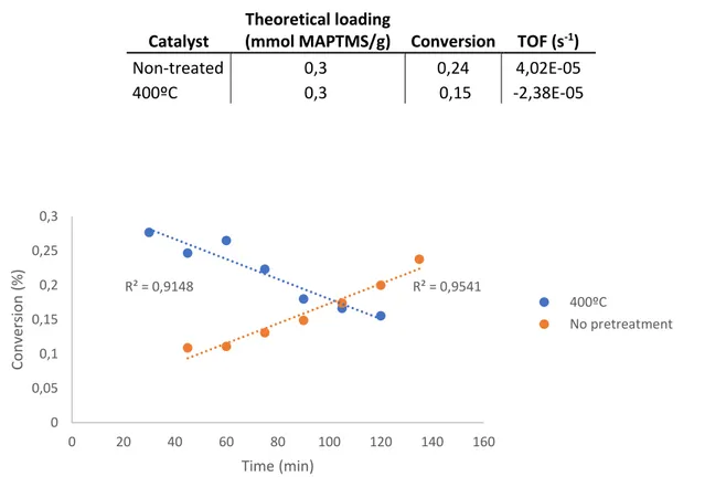
B. Continuous reactor
No steady conversion is achieved in two and a half hours for neither of the two tested membranes, untreated and 400ºC heat treated.
vii 4,02·10-5 s-1, which is in the same range than the TOF of the
membranes tested with the batch reactor.
The 400ºC treated membrane presents a descending tendency line, which means that the catalytic activity worsens with time, this can be due to a poor contact between the reactants and the active sites as the membrane is compressed by the flowing liquid. The membrane has been less resistant to the clumping, derived from the pressure exerted by the liquid flow, than the non treated membrane. The clumping in the membrane should have been prevented or minimised after the heat treatment, so this result is associated to the higher amount of membrane that was introduced in the reactor.
IV. CONCLUSION
Three functionalisation methods have been used in this work, a two step functionalisation where the amine functionalities are added to the membrane after spinning, a direct synthesis where the functionalities are incorporated to the solution before electrospinning and a variant of the direct synthesis where the amine functionalities are added to the membrane while electrospinning. It can be concluded that the only method that achieved successful amine grafting onto the surface is the post functionalisation method, whereas the direct synthesis method was not developed enough to obtain a spinnable functionalised solution, and the coaxial method did not result in satisfactory grafting; although a stable spinning was achieved. The post functionalisation method offers the possibility to tune the physical properties of the material with a heat treatment, such as physical resistance and hydrophobicity/hydrophilicity. However, the higher amine loadings are obtained with untreated membranes.
V. REFERENCES
[1] J. Lauwaert, E. De Canck, D. Esquivel, P. Van Der Voort, J. W. Thybaut, and G. B. Marin, “Effects of amine structure and base strength on acid-base cooperative aldol condensation,” Catal. Today, vol. 246, pp. 35–45, 2015.
[2] S.-H. Pyo, M. Hedström, S. Lundmark, N. Rehnberg, and R. Hatti-Kaul, “Self- and cross-aldol condensation of propanal catalysed by anion-exchange resins in aqueous media.” 2011.
[3] C. Jiang, L. Cheng, and G. Cheng, “Kinetics of aldol condensation of fufural with acetone catalysed by 1.8-diazabicyclo[5.4.0]undec-7-ene,” J. Mater. Sci. Chem. Eng., pp. 65–73, 2018.
[4] E. L. Margelefsky, R. K. Zeidan, and M. E. Davis, “Cooperative catalysis by silica-supported organic functional groups,” Chem. Soc. Rev., vol. 37, no. 6, p. 1118, 2008.
[5] J. Geltmeyer, “Electrospinning and Functionalisation of Silicon Oxide Nanofibres via Sol-gel Technology,” 2017.
[6] E. Margelefsky, “Cooperative catalysis by bifuncionalized mesoporous silica,” California Institute of Technology, 2008.
[7] J. Lauwaert, E. De Canck, D. Esquivel, J. W. Thybaut, P. Van Der Voort, and G. B. Marin, “Silanol-assisted aldol condensation on aminated silica: Understanding
the arrangement of functional groups,” ChemCatChem, vol. 6, no. 1, pp. 255–264, 2014.
[8] S. Sakka and T. Yoko, “Fibres from gels,” J. Non. Cryst. Solids, vol. 147, 1992.
[9] D. Li, J. T. McCann, J. Xia, and M. Marquez, “Electrospinning: a simple and versatile technique for producing ceramic nanofibres and nanotubes,” Am. Ceram. Soc., no. 89, 2006.
[10] B. Breyne, “Functionalisation of APTES with Methyl Red for the production of pH-sensitive silic nanofibres,” 2015.
viii
Table of contents
Confidentiality notice ... i
Acknowledgement ... ii
Copyright notice ... iii
Overwiew ... iv
Extended abstract ... v
Table of contents ... viii
List of figures ... x
List of tables ... xii
List of abbreviations and acronyms ... xiii
1. Introduction ... 1
2. Literature study ... 3
2.1. Aldol condensation reaction ... 3
2.2. Sol-gel science ... 8
2.3. Principle of electrospinning ... 9
2.4. Functionalisation of ceramic precursors ... 14
2.5. Catalytic activity ... 15
3. Thesis Objective ... 16
Chapter 2. Materials and methods ... 17
1. Materials ... 17
1.1. List of chemical structures ... 17
2. Equipment... 18
3. Characterisation ... 18
ix
4.1. Preparation of electrospinning solution ... 19
4.2. Electrospinning setup ... 20
4.3. Catalyst synthesis ... 21
4.4. Reaction ... 21
Chapter 3. Post-functionalisation of silica nanofibres ... 25
3.1.Results ... 26
Chapter 4. Direct synthesis of silica nanofibres with primary and secondary amines 30 4.1.Secondary amine functionalisation ... 30
4.2.Primary amine functionalisation ... 33
Chapter 5. Coaxially electrospun aminated silica nanofibrous membranes ... 35
5.1. Results ... 35
Chapter 6. Batch reactor testing ... 37
6.1. Post-functionalised membrane ... 37
6.2. Coaxially spun membrane ... 38
Chapter 7. Continuous-flow reactor testing ... 40
7.1. Post-functionalised membrane ... 40
7.2. Coaxially electrospun membrane ... 41
Chapter 8. Conclusion and future work ... 43
APPENDIX ... 45
x
List of figures
Figure 1. Electrospinning setup ... 3
Figure 2. Aldol condensation reaction ... 4
Figure 3. Extended scheme of aldol condensation reaction with a primary amine. Lauwaert et al. ... 4
Figure 4. Extended scheme of aldol condensation reaction with an aminated silica supported catalyst. Lauwaert et al. ... 5
Figure 5. Aldol condensation reaction scheme, catalysed with secondary aminated silica ... 6
Figure 6. Solution reactions ... 9
Figure 7. Basic setup for electrospinning ... 10
Figure 8. Modified setup for electrospinning of larger membranes ... 10
Figure 9. Chemical structure of electrospun TEOS membrane. Fresh membrane with water repellent ethyl groups (left), aged membrane with new hydroxyl groups (centre) and hydrophilic heat treated membrane (right) ... 14
Figure 10. Tetraethoxysilane (TEOS) ... 17
Figure 11. 3-aminopropyltriethoxysilane (APTES) ... 18
Figure 12. N-methylaminopropyltrimetoxysilane (MAPTMS) ... 18
Figure 13. Parr batch reactor setup ... 22
Figure 14. Open batch reactor setup ... 23
Figure 15. Continuous-flow reactor setup ... 24
Figure 16. Alternative precursor with a secondary amine function and a choline functional group ... 25
Figure 17. SEM image of functionalised membrane. No heat treated 0,3 mmol MAPTMS/g cat functionalised silica nanofibrous membrane. Shows That the fibres stay intact upon functionalisation, but there are broken fibres. ... 28
Figure 18. Image of non spinnable solution with precipitate. ... 30
Figure 18. 0,01M MAPTMS. 706,3 cP. 15cm. 0,5 ml/h. ... 32
xi
Figure 21. SEM images of washed electrospun membranes. Hexane(left) and
acetone (right). The fibres stay intact after the washing. ... 35 Figure 22. ATR analysis of coaxial membrane washed with organic solvents ... 36 Figure 23. Basket accessory ... 38 Figure 24. SEM images of coaxially spun membranes after batch reactor testing with basket (left) and without basket (right). More broken fibres are observable after the testing without basket. ... 39 Figure 25. Conversion vs. time graph for continuous reactor. catalysts: non
pretreated and 400ºC heat treated membrane ... 40 Figure 26. Continuous reactor conversion vs. time results for coaxially spun
xii
List of tables
Table 1. Amine loading of functionalised membranes. Post-functionalisation……….26
Table 2. Gelation time study. MAPTMS functionalisation………...…31
Table 3. TEOS:EtOH:MAPTMS:HCl:H2O; 1:?:0,1:0,01:2,2………32
Table 4; APTES experiments………..34
Table 5: TOF of the membranes tested in batch reactor……….…37
Table 6: Continuous reactor results for post-functionalised membranes…………...40
xiii
List of abbreviations and acronyms
Acronym or abbreviation
Full name
APTES (3-aminopropyl)triethoxysilane
ATR-FTIR Attenuated Total Reflectance- Fourier Transform Infrared
HMDS Hexamethyldisilazane
HMF 5-(hydroxymethyl)furfural
LUMO Lower unnoccupied molecular orbital
MAPTMS n-methylaminopropyltrimetoxysilane
SEM Scanning electron microscopy
Sol Solution
TEOS Tetraethoxysilane
Chapter 1. Introduction, literature study and thesis objective
1
Chapter 1. Introduction, literature study and thesis
objective
1. Introduction
Aldol condensation reactions play an important role in the petrochemical industry, especially pharmaceutical industry, as it is one of the tools to create carbon-carbon bonds. An example of this is the valorisation of glycerol, which is a byproduct in the production of biodiesel; or the conversion of furan compounds such as 2-furaldehyde (furfural) and 5-(hydroxymethyl)furfural (HMF), which are obtained by dehydration of sugars, into hydrocarbon fuels. [1]
These applications have made aldol condensation a target for catalyst design. A catalyst is a substance which improves the rate of a chemical reaction without undergoing any permanent chemical change itself. With the objective of achieving a greener industry, and more profitable and sustainable processes, a variety of catalysts has been developed for these reactions [2][3]. Nowadays, strong bases such as KOH, Ca(OH)2, NaOH or Na2CO are being used industrially as homogeneous catalysts [4],
which makes this process energy consuming and extremely pollutant.
Along the lines of developing a more sustainable catalyst, heterogeneous catalysis is considered, as heterogeneous catalysts are simpler to separate and reusable [5]. However, homogeneous catalysts still have a better catalytic performance than heterogeneous catalysts. Homogeneous catalysts are in the same phase as the reactants they catalise, whereas heterogeneous catalysts are in a different phase.
Chapter 1. Introduction, literature study and thesis objective
2
In previous studies, amines were grafted onto the surface of a mesoporous silica support. Mesoporous silica, usually SBA-15 (Santa Barbara Amorphous) or MCM-41 (Mobil Composition of Matter) [5], is a solid ceramic material composed of silicon dioxide, whose pore diameter is comprised between 2 nm and 10 nm, on which silanol groups are intrinsically present. These silanol groups improve the catalytic activity of the amines through cooperative catalysis. The surface silanols participate in the reaction forming hydrogen bonds with the reactants, making the resultant intermediates more reactive and improving the catalytic activity of the amines [11][12]. The observed reaction rate is increased when aminated mesoporous silica is used due to the improved adsorption properties of the reagents in the material. The adsorption properties are improved by the high surface area and porosity.
One of the materials known for its high specific surface area are electrospun membranes. These membranes consist of randomly distributed fibres with a diameter smaller than 500 nm, with high porosity up to 90% and small pore sizes ranging from 50 to 500 nm [13]. These properties make them an interesting material to use in catalysis, as they present a high reactive surface area. Silica nanofibres can be electrospun to obtain a non-woven membrane which presents the thermal and chemical resistance, hardness and inert properties of the ceramic materials. [14]
Chapter 1. Introduction, literature study and thesis objective
3 FIGURE 1.ELECTROSPINNING SETUP
Together, silica nanofibrous membranes and amine functionalities can be a good alternative for the homogeneous catalysts used today in aldol condensation reactions. There are several processes tested in this thesis to graft the amines onto the surface of the membrane. The amines can be added to the solution before electrospinning, obtaining a sol that directly produces functionalised membranes, this process is referred as co-condensation or direct synthesis [17]. Amines can also be grafted after the electrospinning, this process is referred as post-condensation [11]. The third option is an alternative to direct synthesis, the solution is electrospun with a special nozzle with two coaxial needles [18], one inside of the other. This method is based on the core-shell spinning technique.
2. Literature study
2.1. Aldol condensation reaction
The aldol condensation reaction consists in two carbonyls that bond forming a β-hydroxyl carbonyl or aldol adduct. This adduct dehydrates into an α, β-unsaturated carbonyl. In this master dissertation, our reactants are acetone and 4-nitrobenzaldehyde.
Chapter 1. Introduction, literature study and thesis objective
4 FIGURE 2. ALDOL CONDENSATION REACTION
The following figure shows the extended reaction mechanism of the aldol condensation with a primary amine catalyst.
FIGURE 3.EXTENDED SCHEME OF ALDOL CONDENSATION REACTION WITH A PRIMARY AMINE.
LAUWAERT ET AL.
Chapter 1. Introduction, literature study and thesis objective
5
When the reaction mechanism is catalysed with aminated silica, the first step is the nucleophilic addition of the acetone to the amine group, in this case a hydrogen bond is formed first between the acetone and the silanol group (1a, Figure 4) and then the addition to the amine group takes place forming a carbinolamine (1b, Figure 4). The dehydration of the previous product forms an enamine (2, Figure 4). Then, 4-nitrobenzaldehyde forms a hydrogen bond with the silanol group (3a, Figure 4) and the formed intermediate reacts with the previous enamine yielding to an iminum ion (3b, Figure 4). Lastly, the imine forms an aldol product in a water-assisted desorption.
FIGURE 4.EXTENDED SCHEME OF ALDOL CONDENSATION REACTION WITH AN AMINATED SILICA SUPPORTED CATALYST.LAUWAERT ET AL.
The steps of the reaction differ when using an aminated silica because of the more reactive intermediates that are formed by hydrogen bonds with the surface silanols, this means that the surface silanols have a promoting effect on the catalytic route, enhancing the performance of the amine catalyst. [8][11][12]
Chapter 1. Introduction, literature study and thesis objective
6
dehydrates in case of using a primary amine. The appearance of the inhibiting specie is the main reason for the higher catalytic activity of the secondary amine catalyst [1][19]. The extended scheme of this reaction is the following (Figure 5):
FIGURE 5.ALDOL CONDENSATION REACTION SCHEME, CATALYSED WITH SECONDARY AMINATED SILICA
Nowadays, homogeneous basic catalysts are being used to catalyse aldol condensation reactions in industry, which is a highly pollutant and energy consuming process. Heterogeneous catalysts offer a greener, more environmentally friendly alternative, as they are reusable and easily separated.[7]
Heterogeneous catalysts present some advantages over homogeneous catalysts, such as:
1. They can be easily recycled.
2. They are easy to separate from the reacting mixture.
Chapter 1. Introduction, literature study and thesis objective
7
Electrospun aminated silica nanofibres are heterogeneous cooperative catalysts. Cooperative catalysis is observed when two entities interact to increase the rate of a reaction beyond the sum of the rates achievable from the individual entities alone [5]. There are different types of interactions:
1. Each entity activates a reactant.
2. The groups sequentially activate one reactant. 3. Each group acts on each other.
4. The surface groups stabilize transition states.
There is a difference between functionalizing the catalyst to improve its behavior (i.e. adding a hydrophobic component to improve the introduction of reactants inside the pores) and cooperative catalysis, as in the last case functionalisation must be involved in the catalytic cycle. [5]
One way to distinguish between cooperative catalysis and surface hydrophobicity is to remove one catalytic entity from the surface and replace it with a homogeneous analog. If there is no cooperation the activity should not be improved by the homogeneous catalyst, however even then it is difficult to separate both effects from each other.
Cooperative catalysis can work by sequential activation, which is enhanced by the proximity of the catalyst species. An example is the synthesis of bisphenol A from acetone and phenol, catalysed by adding a thiol to a strong acid as a co-catalyst. Another option would be dual nucleophilic-electrophilic activation [5].
Sometimes incompatible materials can be immobilized in the silica surface to obtain cooperative catalysis. These groups must be physically close to each other to achieve the promoting effect. Protic solvents promote the proton transfer and neutralization of the incompatible acid and base groups. Aprotic solvents are those which do not accept or give protons, as they do not have neither O-H or N-H bonds.
Chapter 1. Introduction, literature study and thesis objective
8
This protic nature, weak acidity, of the silanols activates the electrophilic reactants via hydrogen bonding. Adding amines produces an increase in the catalytic nature. The first step in amine grafting is an acid-base interaction between the amine and the acidic surface sites (silanols), followed by the reaction of the silane with the nearby silanols, so immobilized amines are found near the acidic sites[5].
In cooperative catalysis, both functional groups must be close to each other, however further information about the precise distance between these groups is not well known. To position multiple functional groups we use imprinting, a technique in which a template molecule is used to guide the collocation of groups. There exists covalent and non-covalent imprinting.
• In covalent imprinting the template molecule is incorporated into the material and cleaved, leaving the functionality.
• In non-covalent imprinting the template molecules are used to position the forming material through H bonding or other non-covalent interaction.
Sol-gel polymerization is used to carry out multiple-point covalent imprinting. Multiple groups can be imprinted using heat to remove each template at the same time. The distance between functionalities can be tuned by tuning the length of the alkyl linker.
2.2. Sol-gel science
Sol-gel science stands for solution and gelation science. A gel is a solution inside which one molecule has reached macroscopic dimensions and has extended throughout it [20]. The macroscopic molecule is the solid phase, which is surrounded by the liquid phase, being both phases continuous.
Chapter 1. Introduction, literature study and thesis objective
9
Sols are obtained by carrying out a hydrolysis and a condensation reaction of the monomeric, tetrafunctional alkoxide recursor, in the presence of water and a solvent. An acid, namely hydrochloric acid (HCl), is utilized as a catalyst for these reactions, so that long polymeric chains are obtained, instead of the aggregates that would be produced using a base catalyzed system. The reaction steps are given in Figure 6 [20].
FIGURE 6.SOLUTION REACTIONS
The hydrolysis reaction (Eq 1, ) replaces alkoxide groups (-OR) with hydroxyl groups (-OH). Subsequently, condensation reactions involving the silanol groups produce siloxane bonds (Si-O-Si) plus the by-products alcohol (ROH) (Eq. 2) or water (Eq. 3). Under most conditions, condensation commences before hydrolysis is complete. Because water and alkoxysilanes are immiscible and react with each other, a mutual solvent such as an alcohol is normally used as a homogenizing agent. However, gels can be prepared from silicon alkoxide-water mixtures without added solvent, since alcohol produced as the by-product of the hydrolysis reaction is sufficient to homogenize the initially phase separated system. Note that this reactions are reversible. [20]
2.3. Principle of electrospinning
Electrospinning is a method utilized to produce continuous, long and narrow fibres with a diameter up to a few hundred nanometers. The principle is based on the stretching of a solution containing a dissolved chain structure into nanometric fibres by the action of electrostatic forces and the evaporation of the solvent.[18]
The basic setup for this process consists of a high voltage power supply, a spinneret (nozzle, metallic needle) and a collector shown in Figure 7. The solution is introduced
Hydrolysis:
≡ 𝑆𝑖 − 𝑂𝑅 + 𝐻2𝑂 ↔ ≡ 𝑆𝑖 − 𝑂𝐻 + 𝑅𝑂𝐻 1
Alcohol Condensation:
≡ 𝑆𝑖 − 𝑂𝑅 + 𝐻𝑂 − 𝑆𝑖 ≡ ↔ ≡ 𝑆𝑖 − 𝑂 − 𝑆𝑖 ≡ + 𝑅𝑂𝐻 2
Water Condensation:
Chapter 1. Introduction, literature study and thesis objective
10
in the spinneret by connecting it to a syringe, the syringe is connected to a syringe pump.
FIGURE 7.BASIC SETUP FOR ELECTROSPINNING
This basic setup often presents variations to adjust to the desired properties of the membrane. In this work a rotating drum grounded collector is used to obtain a large non-woven fibrous mat (Figure 8).¡Error! No se encuentra el origen de la referencia.
FIGURE 8.MODIFIED SETUP FOR ELECTROSPINNING OF LARGER MEMBRANES
Chapter 1. Introduction, literature study and thesis objective
11
Taylor cone once the charges overcome the surface tension and the droplet is stretched into a jet, being deposited as randomly distributed fibres onto the collector as the solvent evaporates.
Historically, electrospinning was limited to organic polymers due to the viscoelastic behavior requirements of the solution. Polymer solutions or polymer melts are
indicated to produce electrospun fibres as they are formed by long chains that can be stretched to form a long fibre. In the same way, sol-gel solutions, or sols, have been tuned to produce long molecular chains in a solvent matrix that can be stretched into long continuous fibres.
2.3.1. Parameters for electrospinning
The influence of the parameters in the electrospinning process is divided into three groups: solution parameters, processing parameters and ambient parameters.
The parameters in the solution which affect its electrospinnability are temperature and composition [21]. The effects of these parameters can be easily tested by measuring the resultant viscosity. When the temperature is increased we can observe an increase in viscosity, and the composition of the solution depends on the polymer to solvent ratio and in the properties of the polymer that is intended to spin.
Stable electrospinning is achieved when the solution is in a specific range of viscosity. Solutions of which viscosity is lower than this form beads in the membrane, solutions with higher viscosities than the maximum range produce unstable Taylor cones, which produce inhomogeneous membranes. The viscosity of the sol affects the diameter of the fibre, higher viscosities lead to thicker fibres.
Chapter 1. Introduction, literature study and thesis objective
12
producing a drop in the needle. However, low feeding rates produce intermittent jets, which produce discontinuous fibres or droplets on the collector.
Humidity and temperature influence the evaporation rate of the solvent. A higher temperature would lead to a faster evaporation of the solvent and a high humidity can trigger pore formation in the surface of the membrane as water droplets are deposited and then evaporated. These parameters influence the diameter of the fibre, increasing it with higher concentrations of precursor and higher feeding rates and decreasing it by lowering the conductivity of the solution. [13] [18]
Steady state electrospinning is what determines the stability of the process. When we can observe a Taylor cone (Figure 7) formed in the tip of the nozzle and the deposition in the collector plate does not show drops of liquid, or other heterogeneities.
An important outcome to consider when the electrospinning process is not stable, is the formation of beads. These beads can appear when the surface tension is not overcome, low viscosity of the solution, low concentration of the ceramic precursor, low voltage. The apparition of beads can be prevented by using a low surface tension solvent and by adding salts to increase the surface charge of the drop.
2.3.2. Electrospinning of sol-gel systems
Polymeric solutions that are spun can be a polymer melt (nylon, polyester) or a polymer mixed with a solvent (rayon, spandex), that solidifies while being spun or when deposited on the collector plate. The main difference between sol-gel and polymeric spinning is that gel solution is not entirely a liquid nor a melt, as stated before, sol-gel solutions are made of a liquid and a solid phase, being the solid phase dispersed in the liquid.
Chapter 1. Introduction, literature study and thesis objective
13
tetrahedra; this linearity leads to more stable spinnability and to obtaining continuous fibres.[21]
The solution is prepared starting from a TEOS () solution to which ethanol is added as a solvent, together with HCl, as a catalyst, and water.
In the last few decades, the interest upon nanofibres has grown due to the wide variety of fields they can be used in, among which we can highlight catalysis, smart textiles, membranes… This interest has encouraged many research groups to come with modifications to sols, which provide new properties to the membranes obtained.
Sols can be modified by adding functional components such as nanoparticles or nanowires to the mixture before electrospinning. Other possibility is to incorporate functional groups, such as amines, to the sol and obtain a functionalised membrane [18].
2.3.3. Properties of electrospun membranes. Hydrophobicity and hydrophilicity
Chapter 1. Introduction, literature study and thesis objective
14
FIGURE 9.CHEMICAL STRUCTURE OF ELECTROSPUN TEOS MEMBRANE.FRESH MEMBRANE WITH WATER REPELLENT ETHYL GROUPS (LEFT), AGED MEMBRANE WITH NEW HYDROXYL
GROUPS (CENTRE) AND HYDROPHILIC HEAT TREATED MEMBRANE (RIGHT)
2.4. Functionalisation of ceramic precursors
Functionalisation refers to the concept of attaching the desired moieties, or functions, onto a matrix [22]. For this purpose, sol-gel technology is useful as it provides either a base matrix to which functionalities can be added later, or a method to directly produce a functionalised matrix. When using an inorganic metal alkoxide precursor, such as TEOS, to produce a sol that can be spun later, we obtain a matrix with the typical thermal and physical properties of a ceramic material, combined with the high porosity and surface area of the electrospun nanofibres [13].
To modify the physical structure of the fibres [18] once the sol has been prepared we can coat the surface of the membrane by vapor deposition, electrostatic interaction or liquid phase attachment. By changing the tip of the nozzle, we can modify the structure of the nanofibre, obtaining core/shell and hollow structures. Core/shell structures can be produced using coaxial needles or immiscible polymers that separate in two phases in the tip of the nozzle.
2.4.1. Two step functionalisation
Chapter 1. Introduction, literature study and thesis objective
15
silica in a stirred round bottom flask, under an inert atmosphere and at 110ºC, with toluene as a solvent for 24 hours. To functionalise the silica nanofibres we can use the same method, although it has been seen that the membrane is visibly deteriorated after the functionalisation.
2.4.2. Co-condensation
The functionalisation process can be also carried out in one step, by adding the desired precursor into the solution before electrospinning it, this is also referred in literature as direct synthesis or direct condensation. In this process the silica precursor is polymerized in presence of functional organosilanes. In some reactions there needs to be a structure directing agent which is later removed chemically, although this removal may disturb the structure of the matrix.
Grafting involves covalently attaching the organosilanes to the surface silanols. More reactive silanes lead to higher organic loadings and clustered surfaces. Normally, trichlorosilanes (more reactive) or trialkoxysilanes (less reactive) are used.[5]
To carry out this functionalisation we simply add the amine functionalities to the solution at the same time we add the solvent and the TEOS.
2.5. Catalytic activity
Chapter 1. Introduction, literature study and thesis objective
16
3. Thesis Objective
This thesis consists of the development of a functional aminated catalyst for aldol condensation, which base is formed of an electrospun silica nanofibre membrane. This electrospun membrane offers the possibility to redirect the aldol condensation industrial production to the more sustainable alternatives of the heterogeneous catalysis, the final goal being to equalize the performance of homogeneous commercial catalysts. In this thesis nanofibrous membranes are introduced to enhance the performance of the catalyst, increasing the number of active sites on the surface of the support, given their high surface area.
Chapter 2. Materials and methods
17
Chapter 2. Materials and methods
1. Materials
For the preparation of the electrospinnable solutions reagent grade tetraethyl orthosilicate (TEOS 98%) from Sigma Aldrich as received, absolute ethanol for analysis from PanReac AppliChem as received, hydrochloric acid (36,5-38,0%) for molecular biology from Sigma Aldrich as received and deionized water from the lab installations were used. For direct synthesis experiments and coaxial spinning 3-aminopropyltrethoxysilane (APTES, 98%) and n-methylaminopropyltrimethoxysilane (MAPTMS, 97%) from abcr Gute Chemie were used as received.
For the membrane post-functionalisation synthesis grade toluene from Fisher Chemicals and methylaminopropyltrimethoxysilane (MAPTMS, 97%) from abcr Gute Chemie were used as received. For the membrane washing anhydrous chloroform (99,8%, stabilized with amylene) from Chem-Lab NV was used as received.
For the reaction testing in continuous and batch reactor reagent grade acetone (99,6%) from Acros Organics, 4-nitrobenzaldehyde (99%) from Acros Organics, reagent grade n-hexane (95%) from Acros Organics and methyl 4-nitrobenzoate (99%) from Sigma Aldrich were used as received.
1.1. List of chemical structures
The chemical structures of the compounds that have been used in this work are the following:
Chapter 2. Materials and methods
18 FIGURE 11.3-AMINOPROPYLTRIETHOXYSILANE (APTES)
FIGURE 12.N-METHYLAMINOPROPYLTRIMETOXYSILANE (MAPTMS)
2. Equipment
For the electrospinning, the solution is contained in a Norm-Ject 10 ml syringe from Henke Sass Wolf, connected to a Sigma Aldrich stainless steel 316 needle with a 90º pipetting blunt. The syringe pump is from KD Scientific, model KDS-100-CE. The high voltage source is from Glassman High Voltage INC, model PS/EH30P03. For the heat treatment a Nabertherm furnace is used.
For the reaction testing a PARR batch reactor model A2590HC11EE and an in-house built continuous reactor.
3. Characterisation
ViscosityChapter 2. Materials and methods
19
Attenuated total reflectance spectroscopy – Fourier transform infrared
(ATR-FTIR)
A Nicolet iS50 with OMNIC software was used to analyze the silica Nanofibrous membranes. The technique uses infrared light and measures the spectrum absorbed by the sample to determine the present bonds.
SEM
The scanning electron microscope is used to take images of the microscopic structure of the membranes and visualize the fibres. The machine is a FEI Quanta 200F.
Optical microscope
The optical microscope is used as a faster, less accurate way to see the microscopic structure of the membranes than the SEM scan. It is an OLYMPUS BX51 equipped with a OLYMPUS TH4-200 camera.
CHNS
We use this type of elemental analysis to calculate the amine loading of the membrane with the amount of nitrogen and the amount of active sites.
HPLC
The high pressure liquid chromatography is used to determine the composition of the samples taken from the reactors while performing an experiment.
4. Methods
4.1. Preparation of electrospinning solution
The silica nanofibrous membranes were produced using a mixture of TEOS, ethanol (EtOH), deionized water and hydrochloric acid (HCl), with a molar ratio of 1:2:2:0.01. TEOS is mixed with ethanol, then the aqueous HCl is added dropwise under vigorous stirring. After the exothermal hydrolysis step, the liquid was heated at 80 °C until the volume decreased to about 3/8th of the initial volume. A spinnable solution is obtained
Chapter 2. Materials and methods
20
The starting solution is functionalised with APTES in the ratio TEOS:EtOH:APTES:H2O:HCl; 1:2,2:0,005:2:0,01. This ratio was modified to obtain a
MAPTMS and APTES functionalisation with more amines. TEOS is mixed with ethanol and APTES, then the aqueous HCl is added dropwise under vigorous stirring. After the exothermal hydrolysis step, the liquid was heated at 80 °C until the volume decreased to about 3/8th of the initial volume. The expected outcome of the experiment is a
transparent viscous solution. The range of viscosity in which spinnability is optimum for APTES functionalised solutions is between 420 and 825 cP [17].
For coaxial spinning the TEOS solution flows through the internal needle, whereas the MAPTMS flows through the external needle. The MAPTMS (97%) used is taken directly from the bottle (Sigma Aldrich).
4.2. Electrospinning setup
Basic setup
We use the basic setup for electrospinning with a 1 ml/h pump rate. The distance from the nozzle to collector is 15 cm, the collector is covered in aluminum foil. The voltage is 22 kV.
Rotating Drum
We use the rotating drum for electrospinning with a 10 ml syringe and a 1 ml/h pump rate. The distance from the nozzle to collector is 15 cm, the collector is covered in aluminum foil. The voltage is 25 kV. Two needles are used.
Coaxial Spinning
Chapter 2. Materials and methods
21
4.3. Catalyst synthesis
4.3.1. Post-functionalisation
Post-functionalisation is carried out in a stirred 250 ml round bottom flask with a cooler and inert atmosphere (argon), at 110ºC for 24 hours. We cut the nanosilica membrane into 1 cm2 squares and introduce them into the flask. We add toluene as a solvent,
MAPTMS as the precursor and the stirrer. We introduce the flask into the 110ºC oil bath and inject the argon gas into the column to obtain the inert atmosphere. For 0,3 mmol MAPTMS/g catalyst we use 0,7 g of membrane, 80 ml of toluene or enough to suspend all the membrane and 0,04 ml of MAPTMS.
After the functionalisation process, remaining unreacted MAPTMS is washed off. To do this we pour the mixture into a vacuum filter and rinse the membrane with chloroform several times. Once this is done we mix the membrane with 150 ml (approximately) of chloroform in an Erlenmeyer flask, and let it stir for 4 hours. Afterwards we vacuum filter this mixture again and store it in a tubular sample holder. The membrane should be vacuum dried for 24 hours at room temperature.
4.3.2. Direct synthesis
Direct synthesis is carried out by adding the amine functionalities to the solution before electrospinning, as it is explained in section 4.1 of Chapter 1.
4.3.3. Coaxial spinning
For coaxial spinning we use the same TEOS solution that is used to prepare the post-functionalised membranes (Chapter 2, 2.1 Preparation of electrospinning solution). This solution flows through the internal needle and MAPTMS, direct from the bottle from Sigma Aldrich, flows through the external needle.
4.4. Reaction
Batch reactor
Chapter 2. Materials and methods
22
the catalyst. The reaction is carried out at 55ºC in a stirred reactor (200 rpm) with a cooling fixture. Samples were taken every 15 minutes during the first hour, and then every 30 minutes and analyzed using HPLC (high pressure liquid chromatography). The internal standard, the catalyst and the solvent are introduced first in the setup and heated up to 55ºC. Separately, the reactants are heated up to 55ºC and are then introduced in the batch reactor with a syringe. The timer is started when the reactants are introduced. An image of the used setup can be seen in Figure 13.
Chapter 2. Materials and methods
23 FIGURE 14.OPEN BATCH REACTOR SETUP
Continuous reactor
Chapter 2. Materials and methods
Chapter 3. Post functionaliation of silica nanofibres
25
Chapter 3. Post-functionalisation of silica nanofibres
The start point is the TEOS spun membrane. A heat treatment can be applied to the membrane to improve its physical properties, as flexibility and thermal and physical resistance. The heat treatment is carried out in a high temperature furnace for two hours, at 400ºC, 500ºC and 800ºC. This treatment will eliminate some of the surface silanols that are present in the membrane and needed for the catalytic activity. A too high heat treatment would eliminate all the silanols in the surface preventing the cooperative catalysis, which is the reason for not exceeding the 800ºC treatment. It is expected that the number of surface silanols decreases with the temperature increase. The heat treatment influences the hydrophobicity of the membrane as the untreated membranes are hydrophobic, whereas the treated membranes become hydrophilic.
The membranes are functionalised with a secondary amine precursor, MAPTMS (Figure 12). Another alternative precursor would be a secondary amine trialkoxysilane with a chlorine group attached to one of the oxygens (Figure 16), the chlorine groups are highly reactive and this would theoretically allow a faster functionalisation by just dipping the membrane in a solution with the precursor. In this case the TEOS membrane can be thermally treated to transform the surface groups into silanols, which would react with the chlorine group, leaving the rest of the molecule attached to the surface with the silicon group, however they are not commercially available.
FIGURE 16.ALTERNATIVE PRECURSOR WITH A SECONDARY AMINE FUNCTION AND A CHOLINE FUNCTIONAL GROUP
Chapter 3. Post functionaliation of silica nanofibres
26
3.1. Results
Table 1 shows the real amine loading of the functionalised membranes:
TABLE 1.AMINE LOADING OF FUNCTIONALISED MEMBRANES.POST-FUNCTIONALISATION METHOD
Heat treatment
(ºC)
Theoretical loading (mmol MAPTMS/g
catalyst)
CHNS loading
(mmol MAPTMS/g cat) Catalyst notes
- 0,3 -
400 0,3 0,15
400 0,3 0,21 No stir. Cut.
800 0,3 0,12
500 1,5 0,10
The real amine loading in the membrane has been calculated via CHNS elemental analysis. The obtained results present some deviations in the nitrogen weight percentage calculated, as membranes that are not functionalised have a higher nitrogen content than the functionalised ones. This can be due to the air content in the membranes, as they have high porosity, which would also explain the higher loading in the non functionalised ones, due to the compression of the treated membranes after the functionalisation.
The loading is calculated by assuming that each amine precursor molecule has two covalent bonds with the surface of the membrane, meaning that there are five carbon atoms left in the molecule per each nitrogen atom. The difference between the carbon percentage before and after functionalisation is calculated, then divided by 100, by the atomic weight of carbon (12.0107 g/mol) and by 5 to obtain the amine loading of the membrane in mmol MAPTMS/g. With this method the loading of the untreated membrane could not be calculated.
𝐴𝑚𝑖𝑛𝑒 𝑙𝑜𝑎𝑑𝑖𝑛𝑔 =𝐶% 𝑓𝑢𝑛𝑐𝑡. 𝑚𝑒𝑚𝑏𝑟𝑎𝑛𝑒 − 𝐶% 𝑛𝑜𝑛 𝑓𝑢𝑛𝑐𝑡. 𝑚𝑒𝑚𝑏𝑟𝑎𝑛𝑒
Chapter 3. Post functionaliation of silica nanofibres
27
For the untreated and heat treated membranes at 400ºC and 800ºC, the target loading was 0,3 mmol MAPTMS/g catalyst, as we can see in Table 1 there are some differences between the loading of the membranes. The same method was followed for functionalising every membrane, except for the stirring, which is tuned in every experiment to make sure the membrane is stirred. The physical effect of the heat treatments is immediately noticed, as the material is harder and easier to manipulate.
The deviation in the measurements are considerable, so in future work they should be analysed again and another method be explored, an example could be titration techniques. Also, the number of surface silanols could be calculated by HMDS/CHNS; the hexamethyldisilazane (HDMS) removes all surface silanols and then they can be calculated by the difference in the results of the CHNS analysis.
The effect of the change in hydrophilicity and hydrophobicity affects the functionalisation of the membrane. As it takes place in an organic solvent, the untreated membrane, which is hydrophobic, is wetted by the toluene of the solution and does not float, allowing for a better contact with the MAPTMS solution. However, the heat treated membranes are hydrophilic, and as they float on the solution the stirring must be more energetic in order to allow a better contact between the surface of the membrane and the functionalities, which damages the membrane. The effect of the hydrophobicity of the membrane cannot be compared with numbers; the untreated membrane is expected to have a higher loading due to the better contact with the solution, although the hydrophobicity of the heat treated membranes can influence in the clumping of the membrane, decreasing it and allowing for a better contact.
Chapter 3. Post functionaliation of silica nanofibres
28
To test the effect of the stirring in the solution, two experiments have been performed with the 400ºC heat treated membrane, one is functionalised with stirring and the other without, both membranes were cut to squares before the functionalisation. It is observed that the stirred membrane has a lower amine loading than the unstirred membrane, this can be due to the clumping in the stirred solution, that compresses the membrane and makes the surface not accessible.
After performing the functionalisation and washing the material, it is observed that the membrane is damaged and the squares to which it has been cut are broken and stick together. SEM images are taken of the membranes after functionalisation to confirm the maintenance of the nanofibrous structure, Figure 17. The fibres stay intact after the functionalisation; however, some broken fibres can be seen in the image, this shows that the nanofibrous structure is not lost. The damage of the fibres is purely related to the stirring and not to the use of harsh chemicals during functionalisation.
FIGURE 17.SEM IMAGE OF FUNCTIONALISED MEMBRANE.NO HEAT TREATED 0,3 MMOL
MAPTMS/G CAT FUNCTIONALISED SILICA NANOFIBROUS MEMBRANE.SHOWS THAT THE FIBRES STAY INTACT UPON FUNCTIONALISATION, BUT THERE ARE BROKEN FIBRES.
Chapter 3. Post functionaliation of silica nanofibres
29
Chapter 4. Direct synthesis of silica nanofibres with primary and secondary amines
30
Chapter 4. Direct synthesis of silica nanofibres with
primary and secondary amines
Pre-functionalisation is an alternative to the post functionalisation, investigated to circumvent the damage caused to the structure of the membrane during the post-functionalisation and to avoid a two step catalyst production.
4.1. Secondary amine functionalisation
At first, functionalisation of the membrane with secondary amines was attempted, as their catalytic activity is higher [10]. To do so, the TEOS solution was prepared adding the amine functionalities before electrospinning, creating a crosslinked sol-gel network wherein the secondary amines are incorporated.
A gelation time analysis was performed by mixing different TEOS:MAPTMS molar ratios (). The gelation analysis is carried out to find out what is the highest amount of amine functionalities achievable for an electrospinnable solution. A solution is not spinnable when it precipitates before the ideal viscosity (Figure 18) is achieved or the viscosity increases too fast to control for electrospinning.
FIGURE 18.IMAGE OF NON SPINNABLE SOLUTION WITH PRECIPITATE.
Chapter 4. Direct synthesis of silica nanofibres with primary and secondary amines
31
precipitation did not occur for two hours, therefore these can be selected for further investigation.
TABLE 2.GELATION TIME STUDY.MAPTMS FUNCTIONALISATION
TEOS MAPTMS EtOH H2O HCl Colour change Precipitation
1 0,005 3 2 0,01 - -
1 0,01 3 2 0,01 22 min 14 min
1 0,01 4 2 0,01 - -
1 0,025 3 2 0,01 30-45 s 18 min
1 0,05 3 2 0,01 10-15 s 7,5 min1
Sol-gel systems with molar ratios of TEOS:MAPTMS 1:0,005 and 1:0,01 were
electrospun, but no homogeneous nanofibrous membrane could be obtained. The
viscosity of the first membrane is 350 Pa·s and the second membrane is 706,3 Pa·s. In this case, no membrane was observed on the collector plate, so no SEM images were taken, this can be due to the low viscosity of the solutions.
We try to obtain more viscous solutions, for this, we choose the highest functionalisation that showed a stable solution, 0,01M MAPTMS, and produced new
1 Colour change: the precipitate is slightly darker or yellowish due to the appearance of precipitate
Chapter 4. Direct synthesis of silica nanofibres with primary and secondary amines
32
solutions of which the solution with the highest viscosity (706,3 Pa·s) produced homogeneous spinning at 15 cm, 0,5 ml/h and 22 kV.
FIGURE 19.0,01MMAPTMS.706,3 CP.15CM.0,5 ML/H.
We can conclude then that MAPTMS membranes can be electrospun into a membrane with low functionalizing ratios.
Once a stable solution has been electrospun with amine functionalities, a solution with a higher amine loading is tried to spin, as a higher amount of amines is needed to test in the reactors. For this we need a functionalisation of 0,5 mmol/g cat, which translates to the ratio of TEOS:MAPTMS 1:0,1, this is ten times higher than the functionalisation that was spun before. The water ratio was increased to 2,2M.
TABLE 3.TEOS:ETOH:MAPTMS:HCL:H2O;1:¿?:0,1:0,01:2,2
EtOH (M)
Gelation time
(min) Precipitate
Precipitation time
(min) T (Cº)
4 - YES 4 80
6 20 NO - 80
8 30 NO - 80
8 34 NO - 60
Chapter 4. Direct synthesis of silica nanofibres with primary and secondary amines
33
Even though initial testing of the gelation time (see Table 2) revealed that sudden gelation occured with amine functionalisation above 1:0,01 molar ratio of TEOS:MAPTMS, further optimisation of the composition of the solution can allow for an spinnable sol. This was investigated for a molar ratio of 1:0,1, by step by step varying the amount of etanol, wáter and HCl, see Table 3. However, no electrospinnable solutions were obtained.
The tuning of the solution consisted on increasing the ethanol ratio to decrease the concentration of the reactants and decreasing the temperature to slow the reaction and obtain a gradual increment of the viscosity.
4.2. Primary amine functionalisation
No spinnable solutions were obtained with the secondary amine precursor because the high speed of the reaction made the tuning of the solution impossible, so it is changed to the primary amine precursor (APTES) as it is less reactive than the MAPTMS. This lower reactivity is due to the ethoxy groups in the APTES (Figure 11), that are less reactive than the methoxy groups of the MAPTMS (Figure 12), and to the lower reactivity of the primary amine, as it is a worse acceptor of hydrogen bonds than the secondary amine [10][23]. A better alternative to the APTES precursor would theoretically be a triethoxysilane with a secondary amine function (Figure 20), as it will reduce the reactivity during the sol-gel process while maintaining the high catalytic activity for the aldol condensation reaction.
Chapter 4. Direct synthesis of silica nanofibres with primary and secondary amines
34
The same procedure is followed namely, obtaining a stable electrospinnable sol by varying the composition of the different components, see Table 4.
TABLE 4.APTESEXPERIMENTS2
EtOH APTES HCl H2O Precipit. t (min) Colour t (min)
8 0,1 0,01 2 6 -
8 0,1 0,005 2 6 -
8 0,1 0 0 - -
8 0,1 0 2 12 8
12 0,1 0,005 2 12 -
20 0,1 0,005 2 15 -
40 0,1 0,005 2 25
40 0,1 0,01 2 35 -
40 0,05 0,01 2 74 -
40 0,05 0 2 58 -
40 0,05 0,02 2 52 -
40 0,05 0,005 1,5 60 -
2,2 0,005 0,01 2 - -
In these experiments we increased the ratio of solvent to prevent precipitation and decreased the ratio of catalyst (HCl) to encourage a slower reaction. These solutions did not form gels, they precipitated forming white flake suspensions. The formation of molecule aggregates can be influenced by a basic character of the solution; however, the pH of the solution was acidic, around 4.
It can be concluded that no spinnable solution was found by this method with enough amine loading to be tested as a catalyst. However, this line of research may be interesting to follow as future work.
2 Colour change: the precipitate is slightly darker or yellowish due to the appearance of precipitate
Chapter 5. Coaxially electrospun aminated silica nanofibrous membranes
35
Chapter 5. Coaxially electrospun aminated silica
nanofibrous membranes
This functionalisation method intends to produce membranes that are directly usable as catalysts. To make sure a high degree of functionalisation is achieved, the membrane is functionalised to reach a theoretical loading of 0,5 mmol MAPTMS/g catalyst.
To functionalise this membrane a coaxial needle is used, where the TEOS sol flows through the central needle and pure, unreacted MAPTMS precursor through the external
needle.
5.1. Results
The elemental analysis shows a real amine loading of 0,399 mmol MAPTMS/g catalyst, which is comparable to the one intended in the post functionalisation method.
To assure that the amine grafting would resist the organic solvents in the reaction process, the samples of the spun membrane are washed with acetone and hexane, and dried. SEM images (Figure 21) of all the samples were taken to make sure the fibres and the amine loading stay intact, we can conclude that the organic solvents do not affect the nanofibrous structure of the membrane.
Chapter 5. Coaxially electrospun aminated silica nanofibrous membranes
36
ATR analysis (Figure 22) was performed on the washed samples, by amplifying the image it can be observed that the amine peaks are smaller after the solvent washing, which can be an indicator of the elimination of the functionalities during the reaction.
FIGURE 22.ATR ANALYSIS OF COAXIAL MEMBRANE WASHED WITH ORGANIC SOLVENTS
Due to the utilised method, it is not possible that the amine precursor evaporates with the ethanol during the electrospinning, as the boiling point of the MAPTMS is 106ºC.
Chapter 6. Batch reactor testing
37
Chapter 6. Batch reactor testing
6.1. Post-functionalised membrane
After the functionalisation of the membranes they are tested in the batch reactor. The results can be seen in Table 5.
TABLE 5.TOF OF THE MEMBRANES TESTED IN THE BATCH REACTOR
Theoretical loading (mmol MAPTMS/g
catalyst)
Heat treatment
(ºC) TOF (s-1)
Final conversion
(%) Catalyst notes
0,3 - 2,09E-04 9,25
0,3 400 2,39E-05 1,40 Run for 24 h.
0,3 400 3,52E-05 1,03 No stir. No cut.
0,3 400 2,99E-05 1,08 No stir. Cut.
0,3 800 2,99E-05 1,55
1,5 500 7,97E-06 1,45
The turn over frequency of a reaction (TOF) is the number of converted molecules by time unit, which implies that the higher is the TOF number, the better is the catalytic performance of the membrane. It is calculated with the slope of the graph which represents conversion vs. time, so the amine loading of the membrane has an important effect on the value. As the data from the elemental analysis is not reliable, the TOF are calculated with the theoretical loading, which is higher than the real loading, this affects the turnover frequency decreasing the real value, as a higher number of active sites is expected.
As it can be observed in Table 5, the best TOF is obtained with the membrane that has not been heat-treated. The experiment with the 400ºC membrane and stirred functionalisation had to be repeated with less amount of catalyst, 0,1 g instead of 0,4 g, so it is run for 24 hours instead of four.
The temperature in the heat treatment does not affect the TOF of the reaction, as the values do not present a significant deviation.