EVALUATION OF INSERTION LOSSES OF ACOUSTIC BARRIERS IN
RAILWAYS BY THE BOUNDARY ELEMENT METHOD
PACS REFERENCE: 43.50.Gf - 43.28.Js
Linares, José Ignacio; Gil, David
Universidad Pontificia Comillas de Madrid - ETSI (ICAI) c/ Alberto Aguilera, 23 - 28015
Madrid Spain
Tel: 00 34 915 422 800 Fax: 00 34 915 596 569
E-mail: [email protected]
ABSTRACT
Boundary Element Methods (BEM) has been hugely used in outdoor sound propagation because it models in an accurate way open domains. Moreover, it's possible to represent sophisticates geometries due to the numerical discretization.
In this paper BEM is applied to evaluate the insertion losses of a barrier near a railway. It has been considered the geometry of the train and its interaction with the top of the barrier (T-shaped and plain one) and the use of absorptive material in some faces of the barrier. Also different types of ground has been studied. The source is assumed a coherent infinite line.
Conclusions about the best position and shape of barrier and influence of the type of ground are presented.
INTRODUCTION
Authors has studied in previous works the applicability of BEM to evaluate the insertion losses by acoustic barriers. Semi-infinite plain barriers had modelled in the first work [1], so it was possible to compare numerical results with analytical algorithms. In a second work [2] ground effect (rigid an soft types) was included in the model, and more complex shapes barriers were considered. The objective of those previous studies was to evaluate insertion losses by acoustic barriers in railway noise. This evaluation, in a preliminary state, is shown in this paper.
Three types of factors has been analysed. In first place ground influence has been considered. So, two types of ground surface has been assumed, a roadside dirt with small rocks and a grass one. In second place the distance between source and barrier has been analysed in order to maximise the insertion losses. At last, the influence of the surface of the barrier in the railway side has been studied. So simulations has been madden with rigid surface and with absorbing surface (mineral wool type) in different thickness.
modelled as an infinite monopole coherent line at the plane of the track but not under the carriage.
Conclusions about the best position of the barrier, its shape and type of surface has been obtained, as a function of ground type.
GEOMETRY AND SOURCE MODEL
Due to usual lengths of train composition a 2D model has been used. The source is a coherent monopole line close to the tracks but not above the carriage (0.75 m height, 2.5 m from medium vertical plane of the carriage). This position has been used by many authors [4,5], who determined this location represents in a simple way the noise produced by tires, engine and power train . Although it's established that dipople pattern radiation models train noise better than monopole one, the difference is only significant when height of the barrier increases [3]. For height used in this paper monopole pattern is right. The frequency studied has been 600 Hz, because is the most significant in railway profile [3].
Ground has been considered as a finite area. This method is easier than semi-space Green function, and avoid some numerical instabilities (irregular frequencies). The accuracy of the method was studied by authors in other works [2].
[image:2.596.83.518.415.592.2]A ballast of trapezoidal shape is considered, 5 m wide in the basis and 3 m in the top, with 0.5 m height. A length of 5 m for ground has been considered at the non analysed side of the carriage. Carriage cross section is 3 m x 3 m, centred in the ballast, and at 0.5 m from its top. Barrier position is variable from 0.6 m to 2.5 m between ballast basis and barrier. Acoustic field has been studied in an area 100 m away from the barrier (horizontal) and 50 m above the ground. Barriers had 3 m height and 0.1 m thickness. Plain and T-shaped has been studied. Figure 1 shows a schematic representation of the geometry previously described.
Fig 1. Schematised representation (not at scale) of the studied problem. Distance "P" will be taken as a parameter.
IMPEDANCE MODEL
A standard BEM implementation developed by Domínguez [6] has been used. In this code boundary condition may be Dirichlet or Neuman type, but impedance one (Robin type) are not allowed. So, authors have modified the code to include this type of condition. A locally reacting impedance behaviour has been assumed, where acoustic impedance has been calculated by Delany-Bazley [7] equation:
P
measurement zone
73 , 0 75 , 0 o f 9 , 11 j f 08 , 9 1 z
Z∞ − −
σ − σ + = (1)
Eq. (1) gives acoustic impedance (Z∞) of a layer of infinite thickness with a rigid termination related to air impedance (zo) as a function of frequency (f) in Hz and flow resistivity (σ) in
[image:3.596.213.385.71.107.2]kN-s/m4. If thickness layer is finite (L), eqs. (2) are applicable.
[ ]
σ + + σ = = − − ∞ 7 , 0 59 , 0 o f 8 , 10 1 j f 3 , 10 k k L k gh cot Z Z (2)Table 1 shows flow resistivity values used in different surfaces. Values for absorbing surfaces correspond with a typical mineral wool, and ballast one has been proposed by Jean [4]. Ground values of 200 kN-s/m4 correspond to a grass type value and 600 kN-s/m4 to roadside dirt with small rocks [8].
Hard ground Soft ground
σ [kN-s/m4] L [cm] σ [kN-s/m4] L [cm]
Ground 600 ∞ 200 ∞
Ballast 100 50 100 50
carriage ∞ --- ∞ ---
covered barrier 30 1 to 10 30 1 to 10
uncovered barrier ∞ --- ∞ ---
Table 1. Flow resistivity values of surfaces used in the study.
RESULTS
Plain Barrier
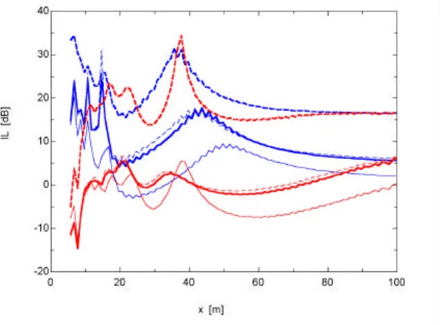
The situation and the thickness of the insulation layer for a plain barrier has been analysed with two types of ground: hard (σ = 600 kN-s/m4) and soft (σ = 200 kN-s/m4). In first place, the optimal barrier position has been determined for hard ground, with the constrain of no larger distance from tracks to not increase too much the investment costs due to a large surface associated to the railway. A parametric study has been developed with distances between ballast basis and barrier from 0,6 m to 2,5 m. Fig. 2 shows an outline of the results. Two evaluation planes has been considered: 1,5 m height (in blue in Fig. 2) and 4 m (in red). These levels can be seen as human ear position and second floor position.
Results in Fig. 2 indicates that there is a higher insulation with a far barrier than in closest one. However, an oscillating behaviour is observed. So, results at 1,25 m are fewer than at 0,6 m. The best position is 2,5 m from ballast basis.
In the previous study surface of barrier in train side was covered by a 5 cm thickness of mineral wool. A second parametric study has been madden to find the best thickness of the insulation layer. Results are schematised in Fig. 3, all cases evaluated at 2,5 m from ballast basis. This figure shows that the larger thickness the better. So, an infinite thickness layer gives the best results. However, in the typical thickness (up to 10 cm), there is no significant difference between 5 cm and 10 cm, so 5 cm is a good option.
[image:3.596.113.483.290.374.2]Fig. 2.- Results for hard ground and plain barrier with 5 cm of mineral wool layer in the train side. Curves in blue are evaluated at y = 1,5 m; curves in red at y = 4 m. Solid thin line represent barrier at 0,6 m from ballast basis; dashed line al 1,25 m and solid thick at 2,5 m.
Fig. 3.- Results for hard ground and plain barrier with different thickness of absorbent layer. Colours as in Fig. 2. Solid thin line represent rigid layer; dashed line 5 cm absorbent layer, solid thick 10 cm absorbent layer and dashed thick infinite thickness of absorbent layer (theoretical case).
which increase the sound pressure levels. In Fig. 4 it can be seen that barrier produces amplifications (insertion losses negatives) except in the zone closest to it.
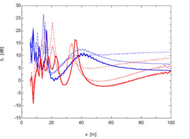
T-shaped Barrier
[image:4.596.148.465.370.604.2]carriage wall and the top of the barrier generates a Helmholtz resonator behaviour. So, it will be possible to maximise the insertion losses if the natural frequencies are found tuning the distance between barrier and train.
Fig. 4.- Results for soft ground and plain barrier with 5 cm of mineral wool layer in the train side. Legend as in Fig. 2.
Fig. 5.- Results for hard ground and T-shape barrier with 5 cm of mineral wool layer in the top (rest of surface rigid). Legend as in Fig. 2.
[image:5.596.153.470.403.635.2]losses are always positive, even at 4 m height, and far away from the barrier they present a plateau.
So, it's necessary to find the most suitable distance from barrier for the most important frequency noise and trying to integrate them in a complex shape barrier so a cascade of suppressed band acoustic filters can be built, in the idea of cuasi-standing waves inside the cavity produced by the interior side of the barrier, the ground and the carriage.
CONCLUSIONS
BEM has been applied to insulation of the railway noise. Behaviour of real surfaces, including ground has been considered by a locally reacting impedance model, based on Delany-Bazley one. Noise source, carriage shape and type of ballast has been taken from typical values. Results has been obtained for 600 Hz, the most important frequency in railway noise spectrum.
Using of a barrier when ground is highly absorbent produce negative effects, because it produces new reflections which increases the sound levels. So, barrier only must be used with hard grounds. In this case, and with plane barriers, it isn't a good option to put the barrier close to the track. Better results are obtained building the barrier at certain distance from the train. Typical thickness of 5 cm are suitable.
A very interesting barrier is T-shape one. The semi-closed domain produced by train wall, ground, barrier wall in the train side and barrier top in the same one produce a standing wave phenomenon mixed with Helmholtz resonator one, which can be tuned to maximise the insertion losses. Future works should be developed trying to integrate all the tuned sizes for each important frequency in a few complex-shape barrier, which maintain the previous idea.
REFERENCES
1. J. I. Linares y D. Gil, “Evaluación de las pérdidas por inserción en barreras acústicas rígidas semiinfinitas mediante el método de los elementos de contorno”, Revista de Acústica, 31, (2000)
2. J. I. Linares y D. Gil, “Consideración del suelo en el modelado de barreras acústicas bidimensionales mediante el método de los elementos de contorno”, Revista de Acústica, 32, (2001)
3. P. A. Morgan, D. C. Hothersall and S. N. Chandler-Wilde “Influence of shape and absorbing surface-a numerical study of railway noise barriers”, Journal of Sound and Vibration, 217, 405-417, (1998)
4. P. Jean, “A variational approach for the study of outdoor sound propagation and application to railway noise”, Journal of Sound and Vibration, 212, 275-294, (1998)
5. D. C. Hothersall, S. A. Tomilson, “Effects of high-sided vehicles on the performance of noise barriers”, Journal of Acoustical Society of America, 102, 998-1003, (1997)
6. J. Domínguez, Boundary elements in dynamics, Computational Mechanics Publications, , (1993).
7. M. E. Delany and E. N. Bazley, “Acoustical properties of fibrous absorbent materials”, Applied Acoustics, 3, 105-116, (1970)

![Table 1 shows flow resistivity values used in different surfaces. Values for absorbing surfaces correspond with a typical mineral wool, and ballast one has been proposed by Jean [4]](https://thumb-us.123doks.com/thumbv2/123dok_es/5467818.112495/3.596.113.483.290.374/resistivity-different-surfaces-absorbing-surfaces-correspond-ballast-proposed.webp)