ACOUSTIC EFFICIENCY OF FALSE CEILINGS: STUDY ON THE INFLUENCE OF DISTANCE FROM THE CEILING SLAB
Referência PACS - 43:55
Patrício, Jorge 1) Schiappa, Fernando 1) Bragança, Luís 2)
1) - LNEC, Av. do Brasil, 1700-066 LISBOA, Portugal
tel.: 351 21 844 3273 ; fax: 351 21 844 3028 ; email: jpatricio@lnec.pt
2) – Universidade do Minho, Campus de Azurém, 4800-058 GUIMARÃES, Portugal tel.: 351 253 510200 ; fax: 351 253 510217 ; email: braganca@eng.uminho.pt
ABSTRACT
Based on the absence of information about the performance of false ceilings, an experimental study regarding the efficiency of continuous false ceilings integrating absorbing material (rockwool) on its hidden surface, placed at different distances from the structural slab was done. The considered distances were respectively 15 cm, 25 cm and 45 cm.
The tests were made both for airborne noise and impact noise. The vibration spectra of the slab and the noise field inside the cavity defined by the false ceiling and the slab were registered. The results obtained led to very interesting and important conclusions.
INTRODUCTION
It is common, in Portugal, the use of continuous false ceilings in housing buildings construction, as an additional decorative element, whose main purpose is normally related to the inclusion of electrical devices, such as modern types of lamps.
It is also currently considered by designers that the acoustic efficiency regarding the increase of noise insulation between apartments - whose horizontal partition is made of a concrete slab with thiknesses in the range of 12 - 17 cm, both for airborne noise and impact noise - provided by these false ceilings are in the range of 3 to 5 dB. The influence of distance (if there´s any) the false ceiling is placed from the slab is always disregarded at the design stage.
The tests were made both for airborne noise and impact noise. The vibration spectra of the slab and the noise field inside the cavity defined by the false ceiling and the slab were registered. The results led to very interesting and important conclusions, supporting the consequent progress of the theme in the future.
TEST FACILITIES
[image:2.596.143.461.354.537.2]The test facilities where the tests were performed are equivalent to those prescribed by the international standard EN ISO 140-1[1]. Its is formed by a reverberation room of 120 m3 volume, in which its global ceiling integrates a partial ceiling, the current test floor made of reinforced concret, of 0,14 cm thickness and surface mass of 350 kg m-2, normally used to evaluate the impact noise reduction of floor coverings. This test floor is rectangular with dimensions of 3,42 m × 2,42 m and it is supported by a continuous resilient strip layer to avoid flanking transmission. The false ceilings were built under this floor. In figure 1 a view of this construction is illustrated.
Fig. 1 – Overview of a false ceiling constructed in the test room
TESTS AND THEORY
To evaluate the changes in performance of these systems, 3 false ceilings were constructed at a distance from the supporting slab of 15 cm, 25 cm and 45 cm. The false ceilings are made of plasterboard with rockwoll on its back surface.
To evaluate the performance of these systems against impact noise, the tapping machine was placed on the laboratory test bare floor. The sound levels spectra was recorded in the reverberation room. The efficiency of the systems was calculated with the follwing equations:
(1)
n no L
L
L= −
where Ln0 represents the normalised impact sound pressure level in the
receiving room produced by the normalized tapping machine hammer impacts on the bare floor and Ln the averaged sound pressure established in the same
room by the normalized tapping machine hammer impacts when the false ceiling was placed. In this case, the parameter ∆L represents the efficiency of the ceiling in frequency bands. Both Ln0 and Ln are expressed in dB.
The averaged sound pressure in a room in frequency bands is obtained in accordance with the following equation:
(2) 10 1 log 10 1 10 / dB n L n j Lj =
∑
=where Lj are the sound pressure levels.
To evaluate the false ceilings performance regarding airborne noise the sound source was placed inside the reverberation room, originating a noise emission field which consequently establishes levels of vibration on the ceiling slab.
This vibration field, mainly due to the propagation of bending waves, is directly converted into radiated noise and to a sound field in an enclosed space, by means of application of theoretical formulas, and the corresponding radiation factors, as follows:
being
Additionally, the sound field established into the cavity defined by the false ceiling and the structural slab (test floor) were recorded in order to evaluate the eficiency of the rockwool for the purpose of reducing the sound field in that cavity, making use of its absorption coefficients previously determined using the stationary waves tube (Kundt).
RESULTS
In the following figures the acoustic efficiency of these false ceilings is presented, both for airborne and impact sound insulation. For the impact sound, the efficiency was calculated from the established relations between the velocity
(
)
1 (3)4 2 2 2 2 2 2 2 2 2 n d n n n m S F v ω η + ω − ω ω >=
< ω
∑
(4) 4 and 2 0 2
0cS v p P c A
vibration levels of the panel, considering the performance of each system. Regarding the airborne sound, the efficiency was calculated based on the performance of each system from the values of vibration velocity. By the fact that was not possible to measure the vibration velocity with enough degree of reliability - the test floor is hardly dissipative -, the calculations were made till the frequency band of 1 kHz. In this case was not advisable to determine the noise insulation index of the system, but it is possile to make an ideia of its performance in frequency domain.
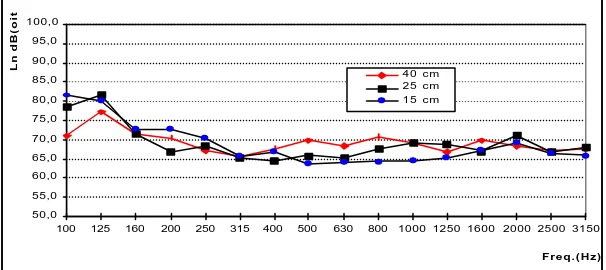
[image:4.596.148.452.371.500.2]Fig. 2 - Impact sound insulation of each false ceiling
Fig. 3 - alse ceilings performance regarding airborne sound
[image:4.596.146.449.580.715.2]In figure 4, the sound field established inside the cavity defined by the false ceiling and the test floor is presented.
Fig. 4 - Sound field distribution inside the false ceiling cavity
40 45 50 55 60 65 70 75 80
100 125 160 200 250 315 400 500 630 800 1000 1250 1600 2000 2500 3150 Freq.(Hz)
Ln dB (oit./3)
Ln0,w = 80 dB Ln,w = 61 dB Ln,w = 61 dB Ln,w = 61 dB
50,0 55,0 60,0 65,0 70,0 75,0 80,0 85,0 90,0 95,0 100,0
100 125 160 200 250 315 400 500 630 800 1000 1250 1600 2000 2500 3150
F r e q . ( H z )
Ln dB(oit./3)
4 0 c m 2 5 c m 1 5 c m
0 0,5 1 1,5 2 2,5 3
100 125 160 200 250 315 400 500 630 800 1000 Freq. [Hz]
Vibration Velocity [100 mm/s]
As a complementary information, some data regarding the material characteristics and some theoretical parameters related to the acoustic fields of the cavity, are presented in the next two figures and in table 1.
[image:5.596.117.483.323.456.2]Fig. 5 – Absorption coefficients of the rockwool.
Fig. 6 - Modal density of the cavity defined by the false ceiling and the slab
Table 1 - Cavity resonances
fn = n c / (2 d)
(Hz)
Value of n
d = 40 cm d = 25 cm d = 15 cm
425 850 1275 1700 2125 2550 2975 3400
680 1360 2040 2720 3400
1133 2267 3400 4533
1 2 3 4 5 6 7 8
d – distance between the false ceiling and the ceiling slab; c – sound velocity in the air; and n – integer number.
0 0,2 0,4 0,6 0,8 1
100 160 250 400 630 1000 1600 2500
Freq. [Hz]
Absorption Coeff.
0 0,5 1 1,5 2 2,5 3 3,5
100 160 250 400 630 1000 1600 2500
Freq. [Hz]
Modal density of the cavity
40 cm
25 cm
[image:5.596.81.514.537.716.2]The frequency resonance of the mass-spring system is below the frequency range of interest (20 Hz for 40 cm distance; 25 Hz for 25 cm distance and 32 Hz for 15 cm distance), which turns it no influent on the system performance.
CONCLUSIONS
Based on this experimental work, several conclusions may be extracted. They are respectively the following ones:
1. The false ceiling efficiency is not influenced by the considered range of distances at which it was constructed from the ceiling slab, both for impact sound and airborne sound;
2. The missing of variations regarding the efficency of this false ceilings with the distance to the ceiling slab may be due to the fact that the false ceiling had to be rigidily suspended. But this is the normal usage.
3. The efficiency of false ceilings can be increased in accordande with the values of sound absorption coefficients of the rock wool or other similar material. The porosity of these products will increase the sound insulation of all the system (false ceiling plus ceiling slab) in medium and high frequencies. On the other hand and because of the resonant panel effect, their density will increase the sound insulation in the low frequencies.
4. The value of coincidence frequency of the ceiling slab is really highlighted, confirming the theoretical predictions for the test floor (frequency band of 160 Hz).
5. The solutions tested are of capital importance for correction of interfaces between residential areas (flats) and adjacent commercial zones (shops and so on).
REFERENCES
[1] - EN ISO 140-1- Acoustics. Measurement of sound insulation in building elements. Part 1: Requirements for laboratory tests facilities with suppressed flanking transmission
[2] - MAIDANIK, G. - Power flow between linearly coupled oscillators. "Journal of Acoustical Society of America", New York, vol. 34, nº 5, May 1962, pp. 623-639
[3] - EN 20354:Acoustics. Measurement of sound absorption in a reverberation room.
[4] - EN ISO 140-3 - Acoustics. Measurement of sound insulation in buildings and of building elements.Part 3: Laboratory measurements of airborne sound insulation of building elements.
[5] - EN ISO 140-6 – Acoustics. Measurement of sound insulation in building elements. Part 6: Laboratory measurements of impact sound insulation of floors
[6] - EN ISO 717-1/2- Acoustics. Rating of sound insulation in buildings and of building elements. Part 1: Airborne sound insulation; Part 2: Impact sound insulation.