SOBRINI GARCÍA
Stage nº202
María Lucía
From 05/09/2016 to 13/01/2017
Factory Futures
PRESIDENT OF THE JURY
Monsieur Thierry DUBBA
INTERNSHIP ADVISER
Monsieur Julien ZINS
PEDAGOGICAL TUTOR
2
TABLE OF CONTENTS
FOREWORD ... 3
ACKNOWLEDGEMENTS ... 4
PRESENTATION ... 5
The project ... 5
The global organization ... 5
The 3DEXPerience platform ... 6
The participants... 7
TECHNICAL REPORT ... 8
1. Introduction ... 8
2. Gantt of the project ... 9
3. Work performed ... 12
3.1. Initial analysis ... 12
3.2. Generation of the process diagrams ... 14
3.2.1. Introduction... 14
3.2.2. Process explanation ... 15
3.3. Design of the assembly line ... 16
3.3.1. Workstations ... 17
3.3.2. Stations ... 19
3.3.3. Factory circulation system ... 23
4. Conclusions ... 25
5. References ... 26
APPENDICES ... 27
APPENDIX 1 – ASSEMBLY PROCESS DIAGRAMS ... 27
APPENDIX 2 –VISUAL WORKPLACE AND PATH DIMENSIONING ... 31
Visual workplace ... 31
3
FOREWORD
This project is the result of my four years of studying at the University of Valladolid and will serve as my Final Project in Industrial Management Engineering. When I started back in 2012 I would have never guessed such an interesting way to put the finishing touch to this phase of my life.
From the very first moment I knew I was coming to Metz the first semester, I have been looking forward to finally present this project. Studying in a very little city in Spain as Valladolid is, can sometimes apart you from the greater opportunities outside. But this experience has also let me build a way more attractive profile for which I am very thanked. The road has not been easy, full of obstacles and struggles, but I will certainly remember this period as one of the bests of my life: full of joy, laughter and solid friendship.
4
ACKNOWLEDGEMENTS
I wish to express my most sincere gratitude to my university, Universidad de Valladolid and the ENIM for their exchange program which allowed me to participate in Factory Futures. I would particularly like to single out my coordinator Juan Ignacio SALGADO for his support in overcoming numerous obstacles I have been facing.
I would like to express my special thanks of gratitude to Mr. Zins who gave me the excellent opportunity to lead this Factory Futures project. His patience, guidance and support have been key to the development of this project.
5
PRESENTATION
THE PROJECT
Factory Futures is a worldwide collaborative project aimed at students in their last years of university. Being the continuation of a series of collaborative projects, Factory Futures lands in the field of Industry 4.0. allowing the participants to learn about the current engineering trends. We count on an essential tool: the 3DEXPerience Platform developed by Dassault Systèmes which brings together all the applications needed for carrying out a fully multidisciplinary project.
With the Learning by doing as the working method, the participants have the opportunity of developing new skills and successfully complete the project by searching innovative formulas for solving the problems encountered. The workload is divided in 9 different work packages according to the different domains of expertise active in the project. A brief explanation of each one is presented below (Fig. 1):
Fig. 1: Explanatory table about the work packages.
THE GLOBAL ORGANIZATION
Each work package was led by a student or professor whose major was closely related with the field of study. Even though the organization within each group was not imposed, the total of the work packages opted for a collaborative working method, making use of the 3DEXPerience platform uncountable opportunities. The students were able to suggest and implement ideas developed by themselves. However, they were guided and advised by professors participating in the project, no matter where they were working from. That is probably the most powerful
Work package
Mission
Smart factory design Distribute and organize the plant and workstations so as to reach a perfect production process.
Process Flow management
Manage, improve and smooth the process flow Collaborative mechanical design Design an innovative mobile station with flexibility on
the production line.
Systems engineering Perform all the automation and control of the transportation system.
Manufacturing and machining Plan the manufacturing procedure of some parts and assemblies.
Ergonomics and Maintenance
Enhance the conditions of the workers.
Robotics Create an additive manufacturing cell using two classic robots.
Cobotics Plan the interaction between the humans and the
robots. Composite design
6 tool of the software: the possibility of bringing together valuable ideas from each corner of the world.
The global organization of Factory Futures was the following (Fig. 2):
Fig. 2: Global organizational chart of Factory Futures
THE 3DEXPERIENCE PLATFORM
The tool that made Factory Futures possible is a professional platform which provides software solutions for every aspect of the project. Thanks to its unique and intuitive interface, it fosters the innovative current trends in industry based in the 3D modelling, analysis, simulation and intelligence in an interactive collaborative environment (Fig.3).
7
THE PARTICIPANTS
This 2016 edition of the collaborative project has brought together 100 participants from 17 universities from around the world, with also the obvious difficulties involved. These obstacles should not be disregard and they mean as well a unique opportunity for the students to experience the current hardships in our global world. Learning another ways of working, points of view and solutions are just some of the lessons learnt throughout this project.
8
TECHNICAL REPORT
1.
INTRODUCTION
According to my major in management engineering I was assigned to the Process Flow Management work package. During this semester in the ENIM, my team and I have always worked towards an optimal environment for producing the turbofan.
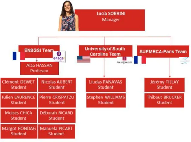
Three universities formed the group: the ENSGSI in France, University of South Carolina in the USA, and SUPMECA-Paris, although this last team was working from Vietnam. Below it is presented an organizational chart with the Process Flow Management participants (Fig.5):
Fig. 5: Organizational chart within the Process Flow Management work package.
For developing the tasks we established the practice of meeting regularly to share the new information we had. The different time zones were an undoubtedly an obstacle, so we decided to do them individually with me. Just in a couple of occasions we were able to reunite the whole team. Nevertheless, we were always in contact, and they were required to send a weekly report with the work completed each week. I also prepared an explaining guide for each task with the useful information I considered.
9
2.
GANTT OF THE PROJECT
Each work package had a very defined mission divided in several tasks placed in a Gantt diagram. This fact allowed the students to plan their work freely so as to reach the milestones established. The time each student could dedicate to the project was undoubtedly a factor to be taken into account. The big majority of them could only work a couple of hours a week in the project, so they needed a task with which they could have certain continuity. The tasks initially assigned to our work package are the following (Fig.7):
Task
Details
Analyze all the Turbofan data
Look for the assembly’s nomenclature, analyze it and if necessary, change it to enhance the nomenclature. This step is the key step of your project!
Analyze the simulations, the workstations etc…
Generate the initiation, planning and executing process diagrams
Create all the diagrams needed for the comprehension of your nomenclature (see images) create the gantt diagram of the project
Adapt the assembly line and workstations to the Factory
Enhance all the existing workstations in agreement with the nomenclature; place the workers and all the accessories.
Adapt the line (For example to receive the Omnimove Kuka robot)
Manage and improve the placement of the different workstations
Using the nomenclature, place the workstations into the factory
(Pay attention when placing them, do it with the agreement of each working group to not disturb their work)
Guarantee a smooth process flow on the assembly lines (analysis)
Perform an analysis (Lean manufacturing) and enhance the assembly line
Manage all the resources (Workers, robots, cobots, mobile station…)
Exchange with all the working groups and evaluate the resources used in each workstation.
Create a resource diagram and a Gantt resources chart
Generate the Gantt Diagram of the resources
Generate the Gantt chart for the entire assembly line
10 Another issue to consider was the fact that no one from the team had ever worked with the 3DEXPerience platform and that meant we also had to reserve a couple of weeks to familiarize with the environment. This is the reason why we decided to let them learn the platform while I was doing the first two tasks and start together with the design of the assembly line.
Therefore, these are the tasks they finally did:
Adapt the assembly line and workstations to the Factory
Enhance all the existing workstations in agreement with the nomenclature; place the workers and all the accessories.
Adapt the line (For example to receive the Omnimove Kuka robot)
Manage and improve the placement of the different workstations
Using the nomenclature, place the workstations into the factory
(Pay attention when placing them, do it with the agreement of each working group to not disturb their work)
Guarantee a smooth process flow on the assembly lines (analysis)
Perform an analysis (Lean manufacturing) and enhance the assembly line
Manage all the resources (Workers, robots, cobots, mobile station…)
Exchange with all the working groups and evaluate the resources used in each workstation.
Create a resource diagram and a Gantt resources chart
Fig. 7: Table with the tasks assigned to the rest of participants.
The division of the tasks was particularly easy because each team could work in an area of the assembly line depending on the members and the workload. This was the distribution (Fig. 7):
11 In the following figure (Fig. 9) we can see the global Gantt diagram of the project with the main phases:
Fig. 9: Global Gantt diagram of the project.
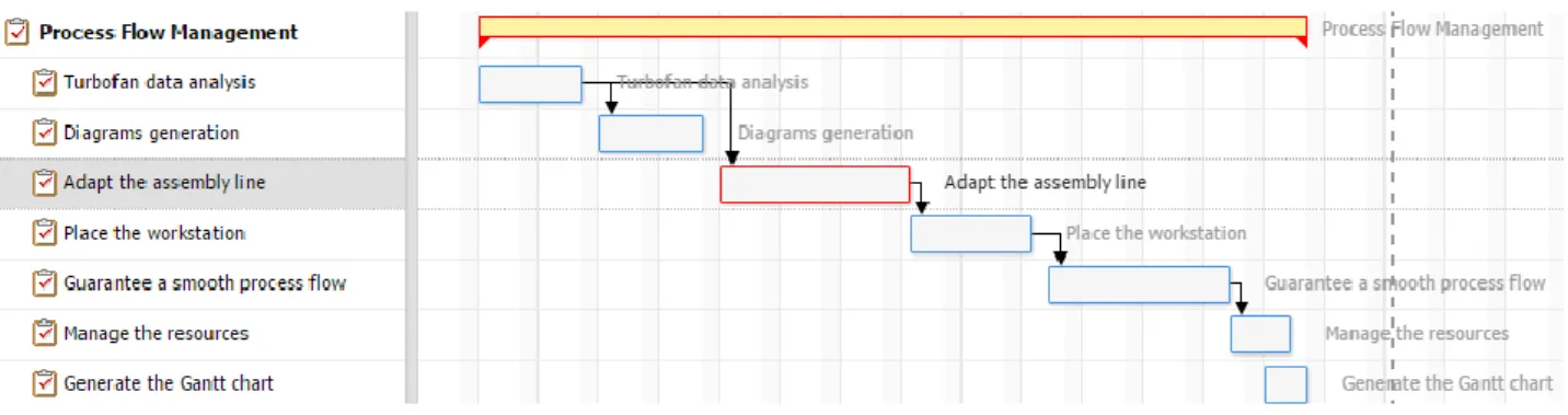
Lastly, the Gantt diagram of the Process Flow Management work package (Fig. 10):
12
3.
WORK PERFORMED
3.1.
I
NITIAL ANALYSISThe aim of this task was to study all the nomenclature already assigned in the project in order to ascertain its appropriateness. We believe in the fact that success always starts with clear concepts and when we talk about a production line this remains essential. The Material Handling Industry of America explains it very clearly: “innovations in technology and the overall magnitude of today’s business environment make it essential that communication be effective and with a minimum of confusion. Thus, it becomes necessary to have available a nomenclature for products or components which are common to the entire industry.”
Throughout the period assigned for this task, we studied the main features that should be present in an appropriate nomenclature in order to be able to compare it with the current that we had.
There is unfortunately not much literature on the subject, but a general idea of a need for clarity and simplicity stems from all of it.
Nowadays, the trend is to find a name that completely defines the part in a concise way; letting the workers differentiate it among others with no doubt from a catalog. It should also include useful information that would help the buyer know a little bit further about the component to acquire.
Experts recommend to choose a first word that should be key to the descriptions, selecting one from a standard basic wordlist for general components. This is by no means a fixed list, but it will change depending the area of the business. Applying the general case to our situation, for defining our SHAFT we could use a “part size length material finish” format, resulting in a shaft 4m 30cm brass. Abbreviations are not recommended but those agreed or standardized are accepted, always using them consistently.
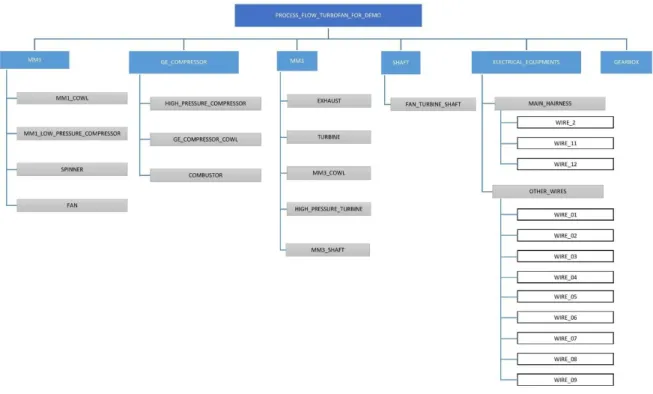
13 The initial nomenclature is presented in the following chart (Fig. 11):
Fig. 11: Chart with the nomenclature of the assembly.
As we can observe, the nomenclature isn’t with a structured format as most of the specialists recommend.
The turbofan is basically composed of 6 main elements which are themselves composed of some other parts. The name chosen for each one is just the standard name we all may now and for the compound names we would represent the space with an underscore (“_”) (eg. HIGH_PRESSURE_TURBINE). This is, however, not applicable to the MM1 and MM3 cases that are just a group of element assembled together. We also have the case in which a particular subcomponent as the COWL is present in two different components. In this case, we would specify first the name of the component and second the name of the subcomponent separated by un underscore (eg. MM1_COWL and MM3_COWL)
When naming the stations we find a much simpler naming convention, as we only distinguish between the workstations (1 and 2) and the stations (from 1 to 5). In the first case, we have two workstations in which operations of transformation of the product are performed. In the second case the 5 stations witness assembly operations.
14 working with the 3DEXPerience platform. In the unlikely event of making this project a reality, a revision of the nomenclature would be needed.
3.2.
G
ENERATION OF THE PROCESS DIAGRAMS3.2.1. INTRODUCTION
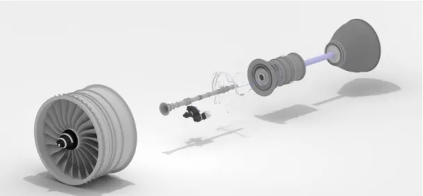
The aim of this task was to document all the turbofan assembly line in order to improve understanding of the whole process. The turbofan to be produced is the Pratt & Whitney Canada PW308C implemented in the Airbus A320 plane (Fig.11).
In this task, we just considered the assembly process, ignoring all the rest of operations related to the production of the components.
Fig. 11: View of the turbofan model in the 3DEXPerience platform.
15 With the initial configuration set in the platform, the turbofan would spend a total duration of 85740,00s or 23,81h, what means that more or less every 2,5 days we would have a turbofan ready to be sent.
3.2.2. PROCESS EXPLANATION
The assembly line is placed in the layout in such way the distances with the stock area are minimal. The configuration is a typical long-shaped space with 2 workstations and 5 stations.
The rest of the diagrams can be found in the Appendix 1 for the Assembly Process Diagrams.
Fig. 13: Plan view of the factory with que assembly line highlighted.
16
3.3.
D
ESIGN OF THE ASSEMBLY LINEWe decided to group together the three tasks related with the design of the line because we considered they were mutually dependent: the new factory should count with an optimal design in every aspect.
In these tasks, we implemented in the platform all the specifications we had set for the workstations. We made use of the Ishikawa diagram to clarify our ideas and decide what we really wanted to appear (Fig. 15):
Fig. 15: Ishikawa diagram for the assembly line requirements.
For the implementation, we based our decisions in the 5S methodology, the main of the Lean Manufacturing thinking. It is a simple tool for organizing the workplace in a clean, efficient, and safe manner to enhance productivity, visual management and to ensure the introduction of standardized working.
Seiri: Sort Seiton: Set in order Seiso: Shine
Seiketsu; Standardize Shitsuke: Sustain
17
3.3.1. WORKSTATIONS
The goal of this part was to change the design of the workstations so as to adapt it to the KUKA OmniMove robot and optimize the space available.
We realized that the central part of the workstation is used to assemble the part of the turbofan which is a good idea we thought we would keep. But there was no place for storing the tools or materials the workers would use during the process, so we had to create a space for this. Moreover, there was too much useless table in the workstation, one could be useful to put a computer if needed but the two others were just taking too much space.The first thing we made was to design a tool area in the workstation, this place would be close to the wall of the back.
18 This was the result after the modification:
We inserted open storage so the worker could easily see the component and put label on the box to remind where the components are and where to store them. We also put a mobile workbench because it is easier if the worker can put all the components and tools he needs for an operation, then move the workbench than always move to look for tool or a component he forgets.
After this we needed to place the KUKA robot which is used to move the part of the turbofan through the assembly line. We chose to put it in the entrance of the workstation because it was easier to reach and easier for workers on the turbofan assembly because there was a larger free space around it.
Fig 18: View of the Workstation 1 with the modifications.
19 This is the final layout of the workstation (Fig.20):
The last choice we made was about how we could bring the part to the workstation. The part is heavy and big so we decided to use a bridge crane which would be useful to move the part from the storage to the workstation.
3.3.2. STATIONS
Stations are the core part of the assembly operations in our plant. In the first two stations the main difficulty was how to move big-sized parts and components and to fit them in the desirable position. Concerning the stations 3, 4 and 5; the challenge was how to manipulate the turbofan being manufactured in order to install the components in very specific positions also difficult to access.
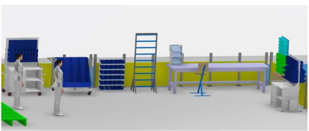
This was the kind of station we had at the beginning:
Fig 20: View of the final Workstation 1 designed.
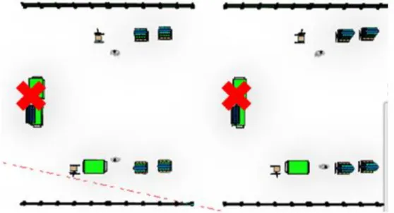
20 The problems we were facing were mainly related with the movement of the KUKA OmniMove throughout the station. So first we deleted all the furniture in the middle of the assembly line.
Once we could assure the free movement of the robot in each workstation we started with the election of the elements that would be placed. Following the Lean thinking we started with the Seiri or Sort step in 5S. It refers to the sorting of the clutter from the other items within the work area that are actually needed. This stage requires a deeper study of the operations carried out in each workstation and to and only leave only those items that are required for the processes in question.
As we were lacking this information we decided to investigate a little bit how other companies such Snecma, Rolls-royce as well as General Electrics were doing these tasks.
Although the operations were not exactly the same, the videos we found were really helpful in certain aspects: above all the way they were transporting all the material throughout the factory. In this way, we discovered that due to the dimensions of the components all the companies were using a bridge crane for moving the products.
In the assembly line, the tasks are mainly basic assembly tasks with the enormous added difficulty of the dimensions. But we suppose that the materials we need to have in each workstations are a wide variety of screws, nuts, washers, rings…
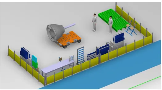
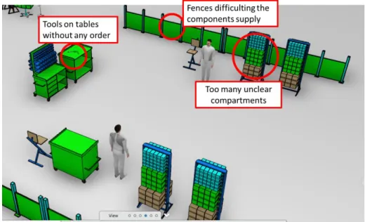
21 The main problems we found are highlighted in the following image:
In order to improve the clarity and order of the station as well as the sourcing system we took a group of decisions. The first one was to delete the fence. We observed that excepting those areas where the robots work independently, the trend in these companies is to have open areas in order to improve visibility. The fences are commonly substituted by paths painted in the floor, and that is the idea we want to implement.
So, applying the Seiri and Seiton this is the cell we designed (Fig.24):
Fig 23: View of the initial Station 1 and 2 with the obstacles highlighted.
22 We need to point that the library in Plant Layout app has limited resources so we couldn’t implement some items we had figured out first.
Now, we would have the tools hanged from the walls and al the materials classified by type. Besides, we would have a clean path for the Logistics to come.
Fig 25: Access for the logistics workers to the stations. Fig 26: Detail of a Kanban trolley.
As we had talked before, the logistics system will be based in the KANBAN system, also widely implemented nowadays in factories. The basic concept of a kanban is a hand sized card that moves with the product or material. It signals when product is to be built or when material can be moved. A company disciplined in lean manufacturing methods will not build product or move material without the proper kanbans (Fig.25).
Another principle of the Just in Time, in fact the most important, is the zero defect objective. It is based in the fact that is way more expensive to fix the errors in the manufactured items than to control them in each step of the production. Therefore, each workstation will count with an system that would let the worker alert the rest of the plant in case he detects something wrong.
It is a quality control process that applies the following four principles:
Detect the abnormality. Stop.
Fix or correct the immediate condition.
Investigate the root cause and install a countermeasure.
Autonomation aims to prevent the production of defective products, eliminate overproduction and focus attention on understanding the problems and ensuring that they do not reoccur.
23
3.3.3. FACTORY CIRCULATION SYSTEM
Now, the main problem that we were facing was how to transport the big components throughout the factory. We saw most of the companies were doing it by air, which helped in the assembly task. We therefore decided to keep the bridge crane as it was before and use it for lifting the turbofan while the Gearbox was being installed.
But even using the bridge crane for the assembly we needed some way to transport the components to the initial point of the bridge crane so as to be able to lift them. Then in one video from General Electric we saw that solution and decided to implement it in the platform. It is basically a forklift attached to a platform that moves freely thanks to the wheels.
Fig 28: Detail of a forklift from General Electrics.
24 For that, we needed to design a new distribution in the plant to separate the paths for the workers, trolleys (KANBAN) and the forklift with the heavy components.
This is what we imagined:
Fig 30: Detail of the storage and tool area in the Stations 1 and 2.
The white path would be for the trolleys, blue for the forklift ant the rest of the space for the workers to walk. Now the three main areas involved directly in the production of the turbofan (stock area, the workstations and the stations) were finally connected. The study for the dimensioning of the paths and the colors chosen can be found in Appendix 2 for the Visual workplace and Path Dimensioning.
25
4.
CONCLUSIONS
Factory Futures has been the perfect reflection of the current trend in society: the need of teams formed by people with complementary knowledges and skills, working together and in an organized way so as to reach a common end. In this case we had to complete a simulated project, but it has certainly prepared us for the real world.
Being part of a team implies working as a team, sharing the same methods, strategies, procedures and techniques. It is undoubtedly not an easy job, because many times entails surrendering one’s methods and convictions to accept others’. However, this process has been much richer for me as a participant as well as for the project.
Luckily for me, I have been able to learn from two different aspects: not only the technical issues related but also the challenges that entails being the leader of Factory Futures. I would be certainly lying if I said everything has been easy and calm throughout this period. The need of motivating people thousands of kilometers away, facing the selflessness of some participants and not being able to control problems beyond my reach has undoubtedly been hard. But there was no bigger motivation than seeing the great opportunity we had for developing new skills and preparing us for the future to come.
26
5.
REFERENCES
Terry Taylor. (2008). Spare Parts Description Naming Convention. 2016, de IDCON inc Sitio web: http://www.idcon.com/resource-library/reliability-tips/973-spare-parts-description-naming-convention.html
Automotive Recyclers Association . (2006). Part Descriptions Guidelines . 2016, de Automotive Recyclers Association website: http://stadiumautoparts.com/files/arapartsdescription.pdf Storage Equipment Manufacturers Association. (2009). Nomenclature for Industrial Grade Steel Shelvi. 2016, de Storage Equipment Manufacturers Association website: http://www.mhi.org/downloads/free/nomenclature_ind_gr_stl_shelving.pdf
Sunita Shelar. (September 2004). Assembly Line Production in Technical Communication. INDUS, India STC Chapter, 1.
F. Mas, J. Ríos, and J. L. Menéndez. (September 2011). Scenario for Concurrent Conceptual Assembly Line Design: A Case Study. The 4th Manufacturing Engineering Society International Conference, (MESIC 2011). 16 September 2016, De ResearchGate Data Base.
27
APPENDICES
APPENDIX 1
–
ASSEMBLY PROCESS DIAGRAMS
The turbofan assembly process begins with the construction of two main components: MM1 and MM3in Workstation 1 and both Workstation 1 and 2 respectively.
We will begin with the MM1, whose assembly process is completed in the Workstation 1. The sequence starts with the transport of the MM1_COWL from the stock area with the help of a bridge crane. Once the component is placed in the right way, the workers carry out all the tasks until obtaining the MMI ready to be moved to the assembly line. The total duration of all the operations is 13980 s (around 3.9 hours).
In parallel to these operations we have another assembly in other side of the Workstation 1. It has a duration of 7200 s and constitutes the first part of the MM3. The rest of the components are added to this construction in Workstation 2 as we will see.
Fig. 1: Perspective view of the MM1.
Fig. 2: Perspective view of the MM3.
28 Once we have these components built, the MM1 is transported to the Station 1 in order to start with the real assembly process. The following steps will be related to the definition of the resources needed to complete all the operations.
Fig. 4: Brief diagram of the MM3 assembly sequence in Workstation 1.
Fig. 5: Brief diagram about the continuation of the MM3 assembly sequence in Workstation 2.
29 When the MM1 reaches the Station 1 a series of operations start which result in the final turbofan.
Fig. 7: Brief diagram of the assembly sequence in Station 2.
Fig. 8: Brief diagram of the assembly sequence in Station 3.
30 This table seeks to reflect a summary of all the tasks in the assembly line. We can obtain it from the 3DEXperience platform.
Fig. 11: Table with operations in the assembly sequence.
31
APPENDIX 2
–
VISUAL WORKPLACE AND PATH DIMENSIONING
V
ISUAL WORKPLACEVisual workplace is a lean concept based in the importance of putting critical information right where employees need to see it. This concept plays an essential role in some of the most popular lean tools, including 5S. With workplace visuals employees have the knowledge they need to eliminate non-value-added waste, improve safety and compliance, and enhance workplace organization.
In that sense, color can be used in several ways for organizing the materials, alerting of certain dangers, or just marking the different areas in the plant. However, the main recommendation we can find in the guides is to use as few colors as we can because otherwise it will get harder to remember the meaning of each one.
Although there are actually no current government-mandated standards defining the colors for including in the plant, there are some similar guidelines developed by agencies that are widely spread. In our case, we have based our decisions in the recommendations Brady Corporation 5S Plus Guide which included a basic color code recommendation (below) that is widely accepted and which complies with any interpretation of OSHA or ANSI codes.
Use:
As the border color for:
Yellow Aisleways, traffic lanes and work cells.
White Equipment and fixtures (workstations, carts, floorstand displays, racks, etc,) not otherwise color coded.
Blue, green and/or black
Materials and components, including raw materials, work-in-progress and finished goods.
Orange Materials or product held for inspection.
Red Defects, scrap, rework and red tag areas.
Red and white
Areas to be kept clear for safety/compliance reasons (e.g. areas in front of electrical panels, fire fighting equipment and safety equipment such as eyewash stations, safety showers and first aid cabinets).
Black and white Areas to be kept clear for operational purposes (not related to safety and compliance).
Black and yellow
Areas that may expose employees to special physical or health hazards (e.g. flammable or combustive material containers); Indicates that extra caution should be exercised when entering and working in the area.
32 We applied these recommendations in the fences using yellow, marking the separation between the work area and the rest of the space.
Fig. 2: Detail of the fence from the assembly line.
We also painted the furniture with soft colors so as to have a nicer environment for the workers. The figure 3 shows the initial look of the furniture in the library and the figure 4 after our modifications. As you can see in the picture, we also added the blue for the boxes in order to comply with the guidelines and mark the work in process.
P
ATH DIMENSIONINGWe have based our decisions in the NTP-434 which is a good practices guide about safe working surfaces and, therefore, the indications are not mandatory but desirable. Due to the importance and the volume of the flow of materials in our plant, we wanted to have a safe and coherent path design.
Fig. 3: Workstation before applying the color recommendations.
33 For security purposes, the guide recommends, where possible, the separation of tracks reserved to pedestrians from those reserved to vehicles and means of transport. For an optimal design of them, the guide highlights three very important parameters to consider.
The frequency of the vehicles and pedestrians.
Maximum dimensions of the vehicles that would move throughout the plant. Maximum dimensions of the goods to be moved throughout the plant. That way, we were facing two different dimensioning problems:
Vehicle path (grey): a one-way lane for moving the GE_COMPRESSOR and the MM3 (both very heavy parts) from the stock area to the stations 1 and 2 respectively.
Fig. 5: In the case of vehicles intended for the carriage of goods. If they are one-way, the width should be equal to the maximum width of the vehicle or load increased by 1 meter. (NTP-434 - 2009 – Safe working surfaces). Dimensions of the figure in millimeters.
In our particular case, the platform attached to the forklift is 1,77 m and so the lane should be 2,77 m so as to comply with the recommendations. (Fig. 6)
34 KANBAN trolleys path (blue): we decided to plan a two-directions lane due to the high
frequency of movement of light materials and fasteners. As an approximation, we have considered the trolleys as vehicles
Fig. 7: Dimensions of the path reserved for the KANBAN trolleys.
Fig. 7: In the case of vehicles intended for the carriage of goods. If they are two-way, the width should be equal to the double of the maximum width of the vehicle or load
increased by 1,4 meter. (NTP-434 - 2009 – Safe working surfaces). Dimensions of the figure in millimeters.