5-Layer Architecture
By Adrian Kearns
Version 0.2 (DRAFT), 22 November 2010
1.
Introduction
... 2
2.
Layered Architecture
... 3
3.
5-Layer Architecture: High-Level Introduction
... 6
3.1.
Overview
... 6
3.1.1.
Contrast to 3-Tier / N-Tier Architecture
... 7
3.1.2.
Separation of the UI
... 7
4.
The Layers – Logical View
... 9
4.1.
Overview
... 9
4.2.
Common Layer
... 9
4.2.1.
Plain Old CLR Objects
... 10
4.2.2.
POCOs’ and Business Logic
... 10
4.3.
Abstraction Layer
... 11
4.4.
Dependency Layer
... 12
4.4.1.
Data Access Components
... 12
4.4.2.
External Service Adapters
... 12
4.5.
Business Logic Layer
... 12
4.6.
Representation Layer
... 13
4.6.1.
User Interfaces
... 13
4.6.2.
System Interfaces
... 13
4.6.3.
System Interfaces vs. the Dependency Layer
... 13
4.6.4.
Interactive Systems Integration
... 14
4.7.
Shared Services
... 14
4.7.1.
Shared Services vs. Common
... 16
4.8.
Anti-Patterns
... 17
4.8.1.
Not Keeping the Abstraction Layer Separate
... 17
4.8.2.
Not Keeping the Common Layer Separate
... 17
5.
The Layers – Physical View
... 18
5.1.
Overview
... 18
5.2.
Common Layer
... 20
5.3.
Abstraction Layer
... 20
5.4.
Dependency Layer
... 20
5.5.
Business Logic Layer
... 20
5.6.
Representation Layer
... 21
6.
Scenarios
... 22
6.1.
Caching
... 22
6.2.
Service Layer
... 22
6.2.1.
Internal / Single System Context
... 22
6.2.2.
External / Multi-System Context
... 22
6.3.
Multi-System Integration
... 23
6.3.1.
Service Adapter to System Interface
... 23
6.3.3.
Shared Commons
... 25
6.3.4.
Shared Data Repository
... 26
6.3.5.
Shared Data Repository with Split Commons
... 26
6.3.6.
Other Integration Options
... 27
6.4.
Plug-ins
... 27
6.4.1.
Attributes
... 28
6.5.
Model-View-Controller Pattern
... 28
6.5.1.
MVC and Classic ASP.NET WebForms
... 28
6.5.2.
MVC and the ASP.NET MVC Framework 2
... 29
7.
Appendix – Glossary
... 30
8.
Appendix – Considerations
... 31
1.
Introduction
This document outlines an architecture which I have called the 5-Layer Architecture. It is specifically suited (but perhaps not limited) to ASP.NET based software solutions.
It reflects “real-world” work that I have been involved in both directly and indirectly since around 2003, and other systems from a wide variety of places – although all of which were ASP.NET based; so you might also refer to it (if you feel so bold) as “Classic 5-Layer ASP.NET Architecture”.
The 5-Layer Architecture generally works at a high level of abstraction, but is fairly prescriptive in some areas; for example, the Representation Layer contains the User Interface components – and both “classic” ASP.NET and ASP.NET MVC based User Interfaces fit equally well.
The 5-Layer Architecture is primarily concerned with the logical and
physical partitioning of code into packages which support reuse (and other goals outlined in 8.1 - Goals).
2.
Layered Architecture
The use of layers within software architecture is nothing new; the
benefits of separating concerns into partitions is at least dimly
understood by most - the ubiquitous “3-Tier” (UL / BL / DAL)
architecture being one of the most commonly discussed.
It should be mentioned at this point that “Layers” are quite different
to “Tiers”.
•
Layers are logical partitions, which may or may not eventually
translate into physical partitions.
•
Tiers are physical partitions which often also imply separation
on different hardware, such as an “Application Tier” (perhaps
referring to a cluster of application servers) or a “Web Tier”.
The reason why I used the term “ubiquitous 3-Tier architecture” is
partly because many often refer to it by this name; tiers and layers
are frequently substituted, and even though most people probably
mean “Layers” the term “Tier” is used.
In “Chapter 3: Architectural Patterns and Styles” (
http://msdn.microsoft.com/en-us/library/ee658117.aspx)Microsoft describes layered architecture as:
“… An inverted pyramid of reuse where each layer aggregates the responsibilities and abstractions of the layer directly beneath it. With strict layering, components in one layer can interact only with components in the same layer or with components from the layer directly below it.”
This is basically correct except for the statement that permits components to “interact” with components from the layer directly below it. To say that it was incorrect might be a little strong, but it could certainly do with clarification.
The point of layering in this way is to help manage dependencies; separations of concern. The problem is that if we take “interacts” to include “referencing”, or in other words: to take something as a
dependency, then we would end up with a system that was bound to its underlying data repository. This is something we very much want to avoid.
are merely constructs that we use in communication (such as a drawing on a two dimensional white board).
It’s easier for us to talk about software (which is inherently abstract) when we apply some sort of thoroughly well understood metaphor from the “real world”. Talking about a software systems logical parts in terms of “layers” helps convey certain meaning, but it brings other meanings as well – some of which don’t necessarily always help.
Therefore, the layered metaphor is at least partially acceptable, so long as any artificial constraints aren’t erroneously applied. It’s not that
components can only interact with components from the layer directly below it, physically; but that they can only interact with components in logical partitions (or layers) beneath it in terms of dependency.
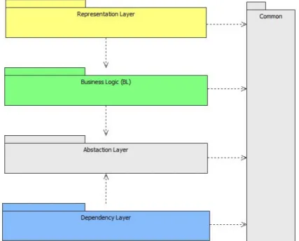
So, a “classic” layered diagram (of the UI / BL / DAL school) might draw the 5-Layer Architecture like this:
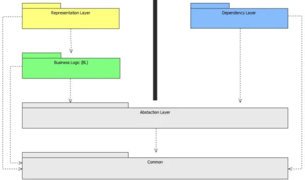
An alternative depiction where the “only those below” rule is strictly applied might look like this:
Figure 2 - The "vertically correct" layered architecture style diagram. The black bar in the “vertically correct” diagram only exists to reinforce the notion that the Dependency Layer does not directly interact with the Representation or Business Logic Layers.
In the 5-Layer Architecture there are (as you might expect) 5 layers, but for clarity it’s far easier to draw the Common layer as a vertical bar to one side, as shown in
Figure 1
.The possible origin of the “horizontal” concept is in diagramming. Sometimes on paper or in a tool, and very frequently on a white board, software is usually drawn as a series of boxes arranged in two
dimensional layers – and often the horizontal and vertical axis are meant to imply some meaning regarding the arrangement of the solution.
3.
5-Layer Architecture: High-Level
Introduction
3.1.
Overview
The architectural starting point is the traditional 3-Layer approach, where the UI, BL and DAL are divided into separate layers; the 5-Layer
Architecture then expands on this by adding a level of abstraction between the BL and DAL, and a “Common” layer which defines all data structures that will exchanged between layers of the solution.
The following diagram shows the main high-level layers and their interdependencies.
Figure 3 - High Level Logical Architecture
• Representation Layer: Provides external access to the solution
(specifically the Business Logic, and by extension the underlying data). This includes User Interfaces and can include System Interfaces such as Http Handlers, JSON Services and so on.
• Business Logic: Contains all the core application logic, with a focus
on implementing business rules and containing business value.
• Abstraction Layer: Contains interfaces which describe any data or
services the BL will consume, in other words: things it depends on.
• Dependency Layer: Contains implementations of the interfaces
defined in the Abstraction Layer.
• Common: Contains anything that has universal scope across the
solution; specifically the definitions of data structures used to pass information between components in the different layers.
of partitioning and architects and designers are encouraged to further partition the system if appropriate.
3.1.1.
Contrast to 3-Tier / N-Tier Architecture
A common driver of the 3-Layer style is to implement a 3-Tier solution, where the UI, Business Layer and Data Access layer can be deployed on to different and separate physical tiers, thus aiding performance via the ability to easily scale-out.
In contrast the 3-Layer approach is more about the separation of concerns in terms of code; the isolation of code and logic into cohesive packages and the management of dependencies.
Traditionally, ASP.NET applications are usually deployed onto a single server – the web server (along with IIS); by this we specifically mean the managed code which implements the UI, BL and DAL. Even in this
arrangement we can physically deploy the database onto a dedicated database server, and multiple instances of the application can be run on different server instances (i.e. under a load balancer of some kind). So the architecture does not preclude the ability to scale-out.
N-Tier (and 3-Tier) Architecture include a specific Data Tier; but where as the 5-Layer Architecture includes the physical data repository and the data access code that accesses it, N-Tier appears to separate the two and only includes the actual data repository within the Data Tier. To quote Wikipedia ( http://en.wikipedia.org/wiki/Multitier_architecture#Three-tier_architecture):
“This [data] tier consists of database servers. Here information is stored and retrieved. This tier keeps data neutral and independent from application servers or business logic.”
5-Layer Architecture includes the data access code as this is usually specific to the data repository (or at least heavily dependant on it); and including data access code and the data repository within the same logical layer does not preclude making changes to either when implemented.
3.1.2.
Separation of the UI
The relationship between the UI and BL is different from the BL and
Dependencies Layer; the direction of dependency is different, but perhaps of more practical relevance is the fact that in ASP.NET applications the UI (or more correctly the Web Server on which ASP.NET relies) also acts as the host of the application.
Solution designers should be free to have their UIs directly consume the BL, or, to add an additional layer; this layer could take several forms:
o A “Service Layer”, which is a Façade presented by the BL; and which is a component of the BL.
o A System Interface that exists as a component within the
Representations Layer; this would be the intermediary between the UL and BL, and between the BL and external consumers.
o A “Service Layer” that exists as a completely separate component.
This architecture allows the direct consumption of the BL for the following reasons:
• Changes to the UI (such as “re-skinning” or complete replacement)
do not impact on the BL.
• Changes to the BL would in any case likely require changes to be
made to the UI as well; and an advantage of this direct
consumption is that the compiler will raise errors – this providing compile-time support rather than forcing the developer to rely solely on runtime tests.
• Allowing direct consumption, particularly when deployed onto the
same server, helps facilitate good performance.
Really significant changes to the UI (such as a complete overhaul) might imply changes to the BL – but only because of overriding business drivers – in which case it is not the UI which is driving change on the BL, but rather a set of new business requirements which affect both.
Finally, just because the UL may directly consume the BL does not mean they must be developed within the same project; source code can (and should) still be divided into separate projects and solutions.
4.
The Layers – Logical View
4.1.
Overview
This section discusses each logical layer in more detail, and introduces Shared Services
Figure 4 - Logical Layers and Key Components.
4.2.
Common Layer
When considering the scope of responsibility, there’ll inevitability be things which are universally consistent across the entire solution; the place for these things is within the “Common” layer. This might include:
• Constants.
• Types (see POCOs’ which are covered below). • Utilities
• Cross-Cutting concerns.
It’s important to remember that we’re still looking at the architecture from a logical perspective. Putting constants into a common layer that is a dependency for all others is nothing to be concerned about, especially when we talking in logical and therefore purely abstract terms. However, incorporating a cross-cutting sub-system like a logging component into the common layer and then translating that directly into physical
The 5-Layer Architecture simply states (right here, in fact) that anything which does not fall into one of the logical UL, BL, Abstraction or DAL layers must fall into the Common Layer; it is then up to the solution designer to decide whether that “thing” is implemented in the Common Package (and which is therefore directly referenced by packages in the other layers), or, kept at the same level as the Common package but not part of it – in which case the other layers can be more selective regarding referencing it.
4.2.1.
Plain Old CLR Objects
Maintaining cohesiveness whilst not imperilling proper separation of concerns is achieved by use of simple data structures defined in the Common layer; these data structures can be implemented either as
classes or struts’. The popular name for these is “POCO” which stands for “Plain Old CLR Objects”.
By defining a common set of types (POCOs’) we get the advantage of a solution that is “strongly typed”; each layer has shared and consistent knowledge of a defined range of data structures, thus providing the following benefits:
• Single Library: As all POCOs’ are defined in the same place they
become easier to manage, held as a single “library” it is easy (for developers) to identify the existence of appropriate types, and add new types without duplication.
• Re-use: as POCOs’ are (mainly) defined with specific business use
cases in mind, they are often re-usable in any instance where that use case applies. This means it often makes sense to pass them between various layers.
The following provides some detail on the rationale behind POCOs’ in the specific context of this architecture.
• Single Responsibility: Each POCO is designed with a specific use
case in mind, so for the most part they aim to do one job and does it well.
4.2.2.
POCOs’ and Business Logic
In a way, POCOs’ represent the most basic form of business logic – in that they usually represent a data structure that has specific business meaning.
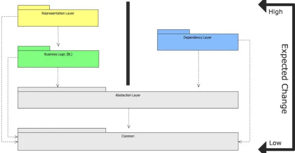
This fits with the Stable Dependencies Principle. If we accept that the basic data structures or concepts within the “business” are fairly stable and don’t change often, but that (relatively speaking) business rules do change more often – then it makes sense to partition business rules and logic into the Business Logic Layer and fundamental data structures into the Common Layer.
Figure 5 - The layers in the context of expected degrees of change.
4.3.
Abstraction Layer
This layer is crucial in managing dependencies; for it is here that we define any abstractions which the Business Logic might depend on.
The most common type of dependency that the Business Logic needs to consume (yet remain loosely coupled from) is Data Access. The 5-Layer Architecture specifically relies on Dependency Inversion (DI); this ensures the Business Logic has a stable underlying layer it can consume for data access, without being physically tied to any specific implementation.
Therefore, the goal of this layer is to protect the rest of the system from undesirable change. If implemented correctly it should be possible to change the implementations of these interfaces without recompiling or redeploying other parts of the system (although changes to configuration may be necessary).
4.4.
Dependency Layer
The Dependency Layer implements interfaces defined in the Abstraction Layer. Provided the dependency tree (as shown in
Figure 4
) is not violated, implementations can take on any other dependency they like.In broad terms there are two kinds of component which are likely to be implemented in this layer: Data Access Components and External Service Adapters.
4.4.1.
Data Access Components
These components provide access to a data repository which stores data the solution “owns”; such as CRUD operations on business objects held in a database, perhaps accessed via an Object Relational Mapping (ORM) tool.
There is no restriction on the exact nature of these components, such as which technology they use, provided they implement interfaces defined in the Abstraction Layer. Implementation might access a database (either directly using ADO.NET, or via an ORM tool) or data held in memory which is persisted to disk as a “flat” file (perhaps using XML or JSON).
4.4.2.
External Service Adapters
These components access data or services provided by external systems, in other words they access data and services which are not “owned” by the current system.
As with Data Access Components, External Data Services can make use of any technology provided they implement interfaces defined in the
Abstraction Layer.
4.5.
Business Logic Layer
This layer encapsulates all complex business rules and logic, for example:
• Processes • Validation • Algorithms
One of the most important goals of this architecture is to ensure the Business Logic is as re-useable as possible; this is achieved by
4.6.
Representation Layer
The main task of this layer is to expose Business Logic to external systems: both end users (people) and other systems.
The 5-Layer Architecture defines two broad types of representation component: User Interfaces and System Interfaces.
4.6.1.
User Interfaces
Generally speaking, User Interfaces are a well understood concept. They are a set of components specifically built to expose functionality, data and processes to end users.
The 5-Layer Architecture allows you to have as many User Interfaces as necessary.
4.6.2.
System Interfaces
System Interfaces expose the data, processes and functionality offered by the Business Logic to other systems. System Interfaces might be
implemented as a Web Service, JSON Service, WCF End-Point or Http Handler.
The actual technology used is irrelevant, as is the number of System Interfaces provided – as long as they are appropriate for the solution you are developing.
4.6.3.
System Interfaces vs. the Dependency Layer
A key difference between System Interfaces and components within the Dependency Layer is that for former exposes functionality to outside parties (where it can be consumed), where as the latter consumes data and services provided by other systems.
Unlike Dependency Layer components, System Interfaces components don’t bring quite the same risks to the solution as the dependency flow is the other way around - they rely on the Business Logic, and so don’t have to be isolated by an Abstraction Layer.
4.6.4.
Interactive Systems Integration
Sometimes the boundary between “providing” and “consuming” is not clear; sometimes the nature of systems interaction is more subtle and the exchange information more complex.
The 5-Layer Architecture provides two approaches for dealing with this:
• Architect the necessary components as Dependency Layer
Components (naturally including appropriate interface definitions in the Abstraction Layer).
• Split operations between the Dependency Layer and System
Integration Layer.
4.7.
Shared Services
Shared Services is the logical container where cross-cutting components go, for example: logging, security and “black-box” components. The Microsoft Enterprise Libraries and the Microsoft Role Membership Provider are examples of the sorts of components that fall under the banner of “Shared Services”.
Where as the other layers have explicit rules regarding dependency, Shared Services do not; however you should be careful when adding any Shared Service as a dependency to any of the main 5 Layers in the 5-Layer Architecture.
There are different types of Shared Services, which can be categorized in following ways.
By ownership and production class:
• Bespoke or custom components that are developed internally. • Open Source components where the code is available but the
overall direction of the component is not under exclusive internal control.
• Commercially procured ‘black-box’ components.
The type of functionality they provide might be:
• Purely technical in nature (messaging, logging sub-systems).
• Business orientated (web services that look-up customer data, audit
logging).
The size, scope and complexity of the component:
• Class libraries which perform discrete functions (such as the
Enterprise Libraries or the AntiXSS Library).
• Sub-systems which include some combination of UI, Logic and Data
Access (such as the Role Membership Provider).
• “Enterprise” class systems which provide a centralized function for a
variety of systems (perhaps a workflow application or federated identity and access management system).
The degree of reuse:
• Used (for the time being) only by the one specific system you are
building.
• Used by many systems.
The frequency of release:
• Frequently Releases; this might be the case for a component which
exists in a volatile market. Releases might not be well advertised, but due to the very frequent nature of release the changes might be comparatively small.
• Regular Release; these may or may not be frequent, but they will
be fairly regular and can therefore be relied upon to a certain extent. Releases (and the product roadmap itself) are always well advertised with sufficient lead-time, providing integrators with sufficient opportunity to deal with change.
• Irregular Release: characterized by no reliable release rhythm, poor
product road map. In-house legacy systems might operate under this class of release frequency. If the system is in anyway critical the release may be well planned with sufficient lead-time but this will depend on the driver behind the release, it’s not uncommon for changes to these types of system to be driven by an unforeseen critical driver, and therefore change with little advanced warning.
• No Planned Releases: probably a legacy system with no updates or
future releases planned.
There are different ways to architect Shared Services into a solution, sometimes the best approach will either be obvious or forced on you, sometimes there will be less restriction. Where there appears to be little restriction you should first identify the nature of the Shared Service by considering the aspects listed in the categories above.
There are then four ways in which the Shared Services components might be “integrated” with the system in question:
1. Direct Dependency: where individual components and layers directly reference a Shared Service component directly.
2. Wrapped by Another Layer: where an existing layer (such as the Common Layer) consumes the Shared Service, and other layers access the Shared Service functionality via that layer.
3. By Interface: a new Abstraction Layer component is built, through which the Shared Service is accessed.
The approach to take depends on the architectural drivers relevant to the solution, and depending on the nature of the Shared Service it might be advisable taking an integration approach that treats the Shared Service more like a related system in its own right, rather than as a child or subordinate component.
For example:
• If the Shared Component offers a specific task that is only used by
specific components (within one or few layers) of the system then direct dependency could be acceptable. This will be particularly appealing if the Shared Component is seen as being relatively stable. The dangers of direct dependency might be mitigated by a regular release cycle that supports changing the nature of the dependency at short notice (such as to accommodate regular upgrades of the Shared Service component).
• If you want to provide a common set of logging methods across all
layers of an entire system (which log to a common cohesive repository), and the logging component itself is very stable then you might consider option 2, via the Common Layer. This would work in situation where you had good control over the project lifecycle – such as an in-house system.
• If you were developing a product for the open market it might be
preferable to use option 3, so that people who use your software have more control over the solution and its dependencies.
• If the Shared Service is a complex business system (and which
continues to be developed and enhanced) then option 4 would provide a safe avenue for integration.
4.7.1.
Shared Services vs. Common
The Common Layer is a “formally” described layer within the 5-Layer Architecture; where as Shared Services isn’t so much of a layer as a dumping ground for anything that doesn’t fit within the other 5 Layers. Having said that, this description is focused on the logical view – in which sense the Shared Services can be thought of as a relevantly coherent collection of components; it’s only when we start to thing of the physical view that things become more chaotic.
Logically, the key difference is that the Common Layer offers
“functionality” that is used by all layers; where as components within Shared Services usually provide functionality that addresses a specific task, and which is often linked strongly to some layers but not others.
Another critical point is that the Common Layer is referenced by all other layers, so it needs to be as free of dependencies as possible; components within Shared Services often bring dependencies that we don’t want to “hard code” the rest of the solution to.
• Constants. • POCO’s.
The Common Layer can also include:
• Common helpers and utilities (as long as they are truly “common”).
Shared Services should include:
• Anything that has dependencies (specifically where those
dependencies fall outside of the formal “5-Layers”).
• Components that are dedicated to a specific task or domain; where
they apply readily to some layers but not others.
• Components whose internal architecture doesn’t align with the
5-Layer Architecture (but more specifically: where it doesn’t align with the particular architecture you are using, which might vary from the full formal description outlined in this document).
4.8.
Anti-Patterns
Having established what the architecture should look like it’s worth taking a moment to review what it shouldn’t look like.
4.8.1.
Not Keeping the Abstraction Layer Separate
Tightly coupling the Abstraction Layer to any other layer means is generally bad. Tightly coupling it to the Dependency Layer completely negates the advantage of loose-coupling, making dependencies difficult to manage.
Tightly coupling to the Business Logic Layer can have the same effect, although as business logic is generally ‘clean’ of external dependences the risk is perhaps much less.
The big problem in tightly-coupling the Abstraction Layer to the
Dependency Layer or Business Logic Layer is that it’s not as easy to split development work between different teams.
4.8.2.
Not Keeping the Common Layer Separate
This is a variation on tightly-coupling the Abstraction Layer to anything else, with the complication that more parts of the system will be
referencing the Common Layer.
5.
The Layers – Physical View
5.1.
Overview
The logical layers define boundaries which directly influence physical boundaries; or more correctly, they define the minimum lines of
separation. So as long as the Abstraction Layer and Dependency Layer are not implemented in the same package you can do what you like.
Where you decide to implement a logical layer using multiple packages it’s likely that the drivers behind that partitioning will drive additional
partitioning in related layers. For example, partitioning the Abstraction Layer into three packages (around specific business concepts) would suggest matching partitioning was appropriate in the Dependency Layer, especially as the Dependency Layer referenced the Abstraction Layer.
In the context of .Net a “package” is effectively an assembly, and although you can compile multiple projects into a single assembly it’s usually more practical to maintain consistency between projects and assemblies.
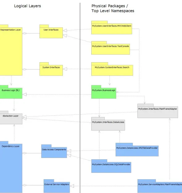
Figure 6 - An example of consistency between logical layers, packages and namespaces.
One note about the diagram shown above, the interfaces directly
reference “non-business” concepts, of which “MainFrameAdapter” is the worst offender. It’s often the case that in organisations where specific legacy systems have existed for a long time that they (to a certain extent) become part of the business domain, although that’s not to say that’s a good thing.
In cases where capability is migrated overtime from one system to
5.2.
Common Layer
Since the Common Layer strongly adheres to the Common Reuse Principle (and is likely to be relatively thin) it most likely that this would be
implemented as a single package.
The most likely scenario where the Common Layer would be implemented using multiple components is where two or more systems shared common data structures (see section 6.3.3 -
Shared Commons
).5.3.
Abstraction Layer
The number of packages implemented here should be influenced by the complexity of the required solution, which in turn is closely related to the influences of the Common Reuse Principle and the Interface Segregation Principle.
Since the Abstractions Layer is deliberately kept as free of dependencies as possible, it should be relatively safe to implement as a single package that can be used by any number of other packages; however, there are cases where it makes sense to implement as separate packages:
• Where the interfaces defined are not related (they don’t share
common closure or reuse).
• Where some of the interfaces defined are sensitive in some way,
and so restricting their publication is advisable.
• Where isolated interface members require additional dependencies
that we don’t want to force on other packages.
5.4.
Dependency Layer
Of all the layers this is the one most likely to be implemented using multiple packages. While it is common to develop a single package that handles all data access for “internal data” (your typical data access layer) things quickly get more complex when you start talking to multiple data sources, external data sources and services.
As always (when designing physical packages) the Common Reuse and Common Closure Principles should be considered.
5.5.
Business Logic Layer
In terms of pure business logic, the “domain” for a business application is usually cohesive, so implementing the Business Logic as a single package is not uncommon – particularly in smaller less complicated systems.
The underlying principles that guide your decision making here are very much around reuse and change:
• You might also consider “stability” in the context of the Stable
Dependencies Principle and Stable Abstractions Principle.
Business Logic can be designed and implemented in a number of ways, including a Domain Model or Domain Driven Design based approach.
If a single package is not desirable, it may be advisable to break the Business Logic into a number of “Business” related packages and a
Common package which contains definitions (interfaces) shared by all. In effect this is repeating the core of the 5-Layer Architecture within the Business Logic Layer. The use of interfaces and Dependency Inversion would allow use of approaches like the Strategy Pattern.
5.6.
Representation Layer
The 5-Layer Architecture treats the Representation Layer similarly to the Dependency Layer (particularly the User Interface components and Data Access components, respectively) in that a User Interface component is treated as a single cohesive component; it specifically ignores the fact that physically it might be made up of client and server based components.
It is very common to have multiple packages in the Representation Layer. There is usually at least one ‘production’ grade UI component and possibly others such as a test harness console or admin console.
Service Interfaces might be included within a User Interface, or they might be implemented separately.
The decision to develop multiple components must, as always, be taken in the context of the current project and its architectural drivers, as well as consideration of relevant principles (the Common Reuse Principle not least amongst them).
5.6.1.
The Client Tier
The 5-Layer Architecture does not formally recognise remote clients as a separate layer. For example, in a web-based context the users’ browser is merely a host in which UI code executes; User Interface components fall within the Representations Layer and implementations are technology specific.
The 5-layer Architecture is primarily concerned with the logical and
6.
Scenarios
6.1.
Caching
The 5-Layer Architecture does not prescribe any specific rules around caching. Caching is usually implemented to address performance needs, and those needs vary from project to project.
There are several high level options to consider:
• Caching might be implemented within a specific Data Access
component, in which case its value is limited to that component. Alternatively the Data Access component might be broken into two sub-layers: a layer directly built against the Abstraction Layer (and therefore common to all Data Access components) which handles caching and a second layer which performs repository specific data access.
• Caching might be built into the Business Logic Layer as a specific
concern.
• The Representation Layer might also include caching mechanisms. • Caching could also be implemented as a Shared Service, but this
might not be efficient depending on the performance profile and caching needs of your solution.
6.2.
Service Layer
The 5-Layer Architecture does not prescribe any specifics regarding the use of a Service Layer.
6.2.1.
Internal / Single System Context
In the context of a single system, a Service Layer is sometimes
implemented “on top” of the Business Logic Layer, and through which all dependant components go through. In the case of 5-Layer Architecture this would mean that all Representation Components would access the Service Layer, which in turn would access the Business Logic.
6.2.2.
External / Multi-System Context
In the context of integration with multiple external systems, a Service Layer would fit into the 5-Layer Architecture as either a Dependency Layer component or a System Interface within the Representation Layer. This assumes that the Service Layer is a specific sub-system provided by the system.
6.3.
Multi-System Integration
At a high level, there are several ways in which you’d sensibly integrate two systems architected in the 5-Layer style, as shown below. These integration approaches can also be used in combination.
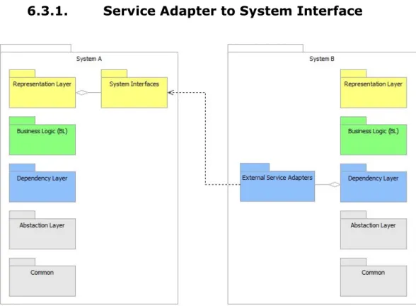
6.3.1.
Service Adapter to System Interface
Figure 7 - Service Adapter to System Interface
Service Adapter to System Interface integration is fairly straight forward; System A provides a System Interface component (such as a WCF end-point, Http Handler or Web Service) as an integration point that a Service Adapter in System B can consume.
6.3.2.
Service Adapter to Service Adapter
Figure 8 - Service Adaptor to Service Adapter This approach is very similar to the previous approach but:
• Both External Adapters are specifically isolated from the rest of
their systems, via the Abstraction Layer.
• Because External Adapters are more loosely-coupled, integrators
6.3.3.
Shared Commons
Figure 9 - Shared Commons
The key point here is that both systems share the Common package, specifically the POCOs’. This allows for a more unified overall solution; as all the involved systems share a common vocabulary, which makes for cleaner integration.
The Service Adapter to System Interface integration shown here is purely illustrative.
6.3.4.
Shared Data Repository
Figure 10 - Shared Data Repository
In this case there is no integration at the software / application level, integration is done through a shared data repository (such as a database).
6.3.5.
Shared Data Repository and Commons
Combining the Shared Data Repository approach with the Shared Commons approach would make a certain amount of sense, as the systems are obviously going to have some common data. In this case they might share the same Common component (specifically the POCO definitions), or, the POCO’s might be split into at least two separate component types:
• A Common component that held the POCO’s for a specific system. • A Common component that held POCO’s shared by multiple
systems.
A Shared Common component is used by all the systems involved; these systems also have their own Common components, which if appropriate, might use or extend POCO’s defined in the Shared Commons.
6.3.6.
Other Integration Options
User Interface Layer:
• The UI in System A might consume UI’s provided by System B;
perhaps via an inline frame or AJAX; in this case the integration is fairly light-weight.
• Dashboard: where System C exists as a Dashboard which is mostly
composed of UI’s provided by Systems A and B. In this case
System C might not have Abstraction and Dependency Layers of its own.
• In the case of a dashboard the underlying Business Layer might be
accessed via a set of Service Interface components or an additional Abstraction Layer that sits “on top” of the Business Logic.
6.4.
Plug-ins
The 5-Layer Architecture doesn’t make any special concessions to plug-ins, but the clearly defined layers should make it easier to identify
opportunities for working with plug-ins.
Plug-ins can have varying degrees of “knowledge and integration” with the host system:
• The plug-in and host system might be completely separated and
(for example) share no common types.
• The plug-in might be required to reference a library provided by the
host system (so as to implement an interface or inherit from a base type.
A plug-in can take various forms and integrate at different places:
• A piece of Business Logic that integrates as a component in the
• A piece of Data Access, which naturally fits “under” the Abstraction
Layer.
• A Representation Layer component (such as a User Interface or
System Interface) that hooks directly (or indirectly) on to the Business Logic Layer. Such a plug-in might exist separately from Representation Layer components provided by the host system, or, they might be co-located and thus appear more cohesive.
All the options above are implemented as components within a single layer; however, multi-layer plug-ins can also be used such as a ‘Module’ within an intranet.
6.4.1.
Attributes
The .Net Framework provides an existing foundation that facilitates plug-ins and modular design: the Attribute.
Attributes serve as metadata that can be used to decorate managed code, including classes, methods, properties and fields.
Attributes can be “read” at runtime, which means that implementers can program against Attributes in a similar fashion to interfaces:
• The host system can provide a set of Attributes (defined within the
Common Layer).
• The plug-in is appropriately decorated with the necessary Attributes. • The plug-in is deployed to the host system.
• When the system runs it uses reflection to detect the plug-in and
access it.
The scenario above effectively implements a form of Dependency Injection; as it is possible (via reflection) for the host system to detect the plug-in (in the form of a DLL, deployed to the bin directory) without having to be recompiled. Essentially the attributes work as an Interface.
6.5.
Model-View-Controller Pattern
One of the ways to test our understanding of the 5-Layer Architecture is to look at how it relates to design patterns that cross those layers; at the time of writing, the Model-View-Controller (MVC) pattern is particularly topical. In addition to the “high level” theoretical / logical view is the more practical “hands-on” view – specifically how this relates to ASP.NET MVC.
6.5.1.
MVC and Classic ASP.NET WebForms
There are different “flavours” of MVC, one of which can be applied to the “Classic” ASP.NET WebForms implementation:
• Controller: the “code-behind” code containing the event handlers
(the .aspx.cs file)
• Model: core logic implemented outside of the Web Project where
the .aspx / .aspx.cs files reside.
In this case the View and Controller are implemented in one project (by ASP.NET WebForms) and the Model is implemented in a separate project; the View and Controller of course fall into the Representation Layer, whilst the Model is part of the Business Logic Layer.
6.5.2.
MVC and the ASP.NET MVC Framework 2
In an Out-Of-The-Box (OOTB) ASP.NET MVC Framework 2 project, basic “separation of concerns” is provided and promoted at the code level; even though they (the Model(s), Views and Controllers) are all part of the same single project - which translates into a single corresponding DLL.
From this starting point the solution designers and developers can decide to break the single OOTB project into multiple ones or retain the existing structure; either can be made to work within the 5-Layer Architecture.
The architectural question is therefore around Common Reuse and
Common Closure as these are directly related to deployment: if the Model is implemented within the ASP.NET MVC’s Web Project then this breaks the physical boundaries but arguably not the logical ones.
Options:
• Single Package: the MVC Model stays where it is (in the single
OOTB project). Doing this limits reuse of the Business Logic but this might be acceptable depending on the requirements, the roadmap of the solution and the architectural drivers. In such a scenario the 5-Layer architecture is maintained logically, but not physically, and the option to refractor to a different architecture at some future point remains.
• Relocate: move the MVC Model completely into the Business Logic
Layer, preserving the logical and physical boundaries of the 5-Layer Architecture.
• Façade / Split: retain the project structure as provided by the
7.
Appendix – Glossary
Abstraction Layer A logical grouping of components that describe various operational contracts (at the code level), and which are used as the basis of Dependency Inversion. The
Abstraction Layer does not contain any implementation.
BL, BLL, Business Logic Layer
A logical grouping of components which contain and implement Business Logic.
Common Layer A logical grouping of components which contains any definitions, constants, code or other resource which has scope over the entire solution, and which is not logically owned by any other layer or component.
DAL, Data Access Layer Code and components which perform tasks associated with accessing and manipulating data held in a persistence store. Data
Access Layers often refers to code that deals with database access, but can refer to any technology that deals with the persistent storage of data, such as file systems.
Dependency Layer A logical grouping that includes Data Access components as well as those which deal with external services. The common factor is that both of these supply data to the Business Logic Layer and both are subject to change that probably originates from drivers
different from those which will drive change on the Business Logic Layer specifically.
Layer A major logical division usually used to organise code; for example, the “Business Logic Layer”. For physical division see “Tier”.
Package A deployable part of a solution; such as a .Net assembly.
Partition An isolated part of a larger entity;
specifically a logical boundary which may also translate to a physical boundary.
POCO, Plain Old CLR Object The .Net equivalent of a POJO. A POCO is a simple class object, and in the 5-Layer Architecture is used as a simple dedicated container for data. POCO’s can be
Representation Layer A major logical layer which contains both User Interface and System Interface components.
Shared Services Libraries, utilities and any other resource which is (or can be) used by more than one layer.
Tier A major physical division, and refers to an
environment where code is deployed and executed. The term tier can also imply division at the server level, not just at the package level; for example, a “database tier” might refer to a farm of dedicated database servers. For logical division see “Layer”.
UI, User Interface Where interaction between humans and machines occurs; specifically code and components that implement a User Interface.
8.
Appendix – Considerations
8.1. Goals
• To separate responsibilities for maximum re-use.
• Loose-coupling of Business Logic from Data Access; specifically to
assist management of dependencies.
• To partition the system so that different parts can be developed
independently of each other - by different teams if need be.
8.2. Assumptions
• All packages will be deployed onto the same server; however, they
could be deployed onto different servers if desired.
8.3. Design Drivers
• Interface / POCO driven:
o Interfaces define the sorts of things the system needs. o POCO’s define data structures used throughout the system.
• Interface and POCO design is mostly driven by business orientated
does not violate any of the rules, and does not warp the Business Logic.
The business logic that a solution implements is typically is the centre of gravity as far as change goes; therefore the business logic is also the starting point for design work – which translates to work starting in the Business Logic Layer.
How this ripples out and affects the rest of the system is firstly via the external interfaces the Business Logic exposes: specifically by:
• Interfaces defined in the Abstraction Layer. • POCO’s defined in the Common layer.
8.4. Rules
• The dependency tree (the inter-dependencies and direction of
dependence between all layers) must be strictly adhered to.
• The purpose of each layer must be observed (e.g. don’t sneak Data
Access code into the Business Logic).
• The high level layers represent the minimum separation between
packages.
• POCOs’ can be nested.
• POCO’s can be implemented as either .Net Classes or Structs. • UI can directly consume BL, but may go through an additional layer
of abstraction if appropriate.
• The high level layers represent the minimum separation between
packages; these packages may in turn be partitioned further if appropriate.
• Additional Abstraction Layers can be added where appropriate.
8.5. Suited for
• Web-based applications.
8.6. Design Principles Followed
• Dependency Inversion Principle • Single Responsibility Principle • Stable Abstractions Principle • Stable Dependencies Principle