GENERATION AND CONTROL OF LOCOMOTION FOR BIPED ROBOTS BASED ON BIOLOGICALLY INSPIRED APPROACHES.
Julián Efrén Cristiano Rodríguez
Dipòsit Legal: T 254-2016
ADVERTIMENT. L'accés als continguts d'aquesta tesi doctoral i la seva utilització ha de respectar els drets de la persona autora. Pot ser utilitzada per a consulta o estudi personal, així com en activitats o materials d'investigació i docència en els termes establerts a l'art. 32 del Text Refós de la Llei de Propietat Intel·lectual (RDL 1/1996). Per altres utilitzacions es requereix l'autorització prèvia i expressa de la persona autora. En qualsevol cas, en la utilització dels seus continguts caldrà indicar de forma clara el nom i cognoms de la persona autora i el títol de la tesi doctoral. No s'autoritza la seva reproducció o altres formes d'explotació efectuades amb finalitats de lucre ni la seva comunicació pública des d'un lloc aliè al servei TDX. Tampoc s'autoritza la presentació del seu contingut en una finestra o marc aliè a TDX (framing). Aquesta reserva de drets afecta tant als continguts de la tesi com als seus resums i índexs.
ADVERTENCIA. El acceso a los contenidos de esta tesis doctoral y su utilización debe respetar los derechos de la persona autora. Puede ser utilizada para consulta o estudio personal, así como en actividades o materiales de investigación y docencia en los términos establecidos en el art. 32 del Texto Refundido de la Ley de Propiedad Intelectual (RDL 1/1996). Para otros usos se requiere la autorización previa y expresa de la persona autora. En cualquier caso, en la utilización de sus contenidos se deberá indicar de forma clara el nombre y apellidos de la persona autora y el título de la tesis doctoral. No se autoriza su reproducción u otras formas de explotación efectuadas con fines lucrativos ni su comunicación pública desde un sitio ajeno al servicio TDR. Tampoco se autoriza la presentación de su contenido en una ventana o marco ajeno a TDR (framing). Esta reserva de derechos afecta tanto al contenido de la tesis como a sus resúmenes e índices.
biped robots based on biologically
inspired approaches
DOCTORAL THESIS
Author:
Juli´an Efr´en Cristiano Rodr´ıguez
Advisors:
Dr. Dom`enec Savi Puig Valls
Dr. Miguel ´
Angel Garc´ıa Garc´ıa
Departament d’Enginyeria Inform`atica i Matem`atiques
To God, thank you for walking by my side today and always.
To my parents Efr´en and Blanca.
To my brother Juan and my sister Karen.
To my niece Silvia and my dear Luc´ıa.
To the memory of my grandfather and my grandmother.
Abstract
This thesis proposes the use of biologically inspired control approaches to generate
and control the omnidirectional gait of humanoid robots, adapting their movement to
various types of flat terrain using multi-sensory feedback. The proposed locomotion
control systems were implemented using Central Pattern Generator (CPG) networks
based on Matsuoka’s neuron model. CPGs are biological neural networks located
in the central nervous system of vertebrates or in the main ganglia of invertebrates,
which can control coordinated movements, such as those involved in locomotion,
respiration, chewing or swallowing.
The fact that, in nature, human and animal locomotion is controlled by CPG
networks has inspired the theory on which the present thesis is based. In particular,
two closed-loop control architectures based on CPG-joint-space control methods have
been proposed and tested by using both a simulated and a real NAO humanoid
robot. The first control architecture identified some important features that a
CPG-joint-space control scheme must have if a useful locomotion pattern is to
be described. On the basis of this analysis, the second control architecture was
proposed to describe well-characterized locomotion patterns. The new system,
characterized by optimized parameters obtained with a genetic algorithm (GA),
effectively generated and controlled locomotion patterns for biped robots on flat
and sloped terrain.
To improve how the system behaves in closed loop, a phase resetting mechanism
for CPG networks based on Matsuoka’s neuron model has been proposed. It makes
it possible to design and study feedback controllers that can quickly modify the
locomotion pattern generated.
The results obtained show that the proposed control schemes can yield
well-characterized locomotion patterns with a fast response suitable for humanoid
robots with a reduced processing capability. These experiments also indicate that
the proposed system enables the robot to respond quickly and robustly, and to cope
Keywords: Biped locomotion, Robotics, Humanoid Robots, Adaptive control,
Biologically inspired control, Central pattern generators, CPGs, Phase resetting,
Acknowledgements
I would like to express my gratitude to my advisors Dr. Dom`enec Savi Puig Valls
and Dr. Miguel ´Angel Garc´ıa Garc´ıa for giving me the opportunity to work under
their academic supervision and for their dedication, guidance and support during
these years.
I would like to thank my parents Efr´en and Blanca, my brother Juan, my sister
Karen, my niece Silvia and my dear Luc´ıa for their love, encouragement and support.
Likewise, the affection and support that I have received from all my family and friends
in Colombia and Spain have been fundamental to me.
During the last years I have met many people from whom I have learnt a lot. To
all of them, thank you very much for each of the great moments that we have shared
and also for the great talks that I am completely sure we have had. I also would
like to thank each of the former and current members of the Intelligent Robotics and
Computer Vision Group for their companionship and friendship.
I would like to thank Fundaci´on Carolina and Universitat Rovira i Virgili for the
financial support given to me through a doctoral scholarship.
Last but not least, I want to express my gratitude to all those anonymous
Contents
Abstract . . . i
Acknowledgements . . . iii
Contents . . . v
List of figures . . . ix
List of tables . . . xiii
1 Introduction 1 1.1 Motivation . . . 1
1.2 Objectives . . . 3
1.2.1 General objective . . . 3
1.2.2 Specific objectives . . . 4
1.3 Overview . . . 4
2 State of the art 7 2.1 Biped locomotion . . . 7
2.2 Locomotion control systems for biped robots . . . 11
2.2.1 ZMP-based control methods . . . 13
2.2.2 Biologically inspired control methods . . . 14
2.2.2.1 CPG-task-space control methods . . . 16
2.2.2.2 CPG-joint-space control methods . . . 17
2.2.2.3 Estimation of CPG network parameters through genetic algorithms . . . 19
2.3 Central pattern generators . . . 21
2.3.1 Introduction . . . 21
2.3.2 Matsuoka’s oscillator . . . 23
2.3.3 CPG networks based on Matsuoka’s neuron model . . . 27
3 Proposed systems for locomotion control 31 3.1 Introduction . . . 33
3.1.1 NAO humanoid robot . . . 33
3.1.2 Robotics simulator . . . 34
3.2 First control scheme . . . 35
3.2.1 CPG network topology . . . 36
3.2.2 Automatic estimation of CPG network parameters . . . 38
3.2.3 Feedback strategies . . . 39
3.2.4 Experimental results and discussion . . . 43
3.2.5 Conclusion . . . 46
3.3 Second proposed control scheme . . . 47
3.3.1 CPG network topology . . . 48
3.3.2 Automatic estimation of CPG network parameters . . . 50
3.3.3 Feedback strategies . . . 52
3.3.4 Omnidirectional controller . . . 55
3.3.5 Experimental results and discussion . . . 56
3.3.6 Conclusion . . . 66
3.4 Summary . . . 68
4 Phase resetting mechanism 71 4.1 Introduction . . . 72
4.3 Proposed phase resetting . . . 74
4.3.1 Frequency characterization . . . 75
4.3.2 Online phase estimation . . . 77
4.3.3 Phase resetting strategy . . . 79
4.4 Experimental results and discussion . . . 82
4.4.1 Simulation results . . . 82
4.4.2 Application to bipedal locomotion: Fast synchronization of the interaction between the robot’s feet and the terrain . . . 87
4.4.3 Application to bipedal locomotion: Fast balance recovery . . . 89
4.5 Summary . . . 94
5 Conclusions 95 5.1 Summary of contributions . . . 96
5.1.1 CPG-joint-space control schemes for generating and controlling well-characterized locomotion patterns for biped robots on flat terrain . . . 96
5.1.2 Well-characterized CPG-joint-space control scheme for the locomotion control of biped robots on inclined terrain . . . 97
5.1.3 Phase resetting mechanism for CPG networks implemented with Matsuoka’s neuron model . . . 98
5.1.4 Well-described system for the detailed study of phase resetting controllers for quick recovery after loss of balance . . . 99
5.2 Future research lines . . . 99
5.2.1 Detailed analysis of the parameters that characterize the second control scheme proposed . . . 99
5.2.2 Detailed analysis of phase resetting controllers for the locomotion control of biped robots . . . 99
5.2.3 On-line learning of phase resetting controllers . . . 100
5.3 Publications derived from this thesis . . . 101
5.3.1 Journals . . . 101
5.3.3 Spanish conferences . . . 102
List of Figures
2.1 CoP location . . . 9
2.2 Desired dynamic stability margin . . . 10
2.3 Three examples of biped robots. From left to right: Passive Dynamic Walker, Petman and Asimo. . . 11
2.4 CPG-task-space control . . . 16
2.5 CPG-joint-space control . . . 17
2.6 Schematic representation of Matsuoka’s non-linear oscillator . . . 24
2.7 Simplified topology of 2-neuron Matsuoka’s CPG (Matsuoka’s oscillator) 25 2.8 Output signals of Matsuoka’s oscillator . . . 26
2.9 Example of amplitude modulation by varying parameter ue . . . 26
2.10 Example of frequency modulation by varying parameter Kf . . . 27
2.11 CPG network of 3 neurons as proposed in (Matsuoka, 1985) . . . 28
2.12 Output signals of the 3-neuron CPG shown in fig. 2.11 . . . 29
2.13 4-neuron CPG network as proposed in (Matsuoka, 1985) . . . 29
2.14 Output signals of 4-neuron CPG shown in fig. 2.13 . . . 29
2.15 4-neuron CPG network as proposed in (Matsuoka, 1985) . . . 30
2.16 Output signals of the 4-neuron CPG shown in fig. 2.15 . . . 30
3.1 NAO humanoid robot . . . 35
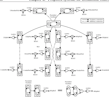
3.2 Proposed topology for the CPG network . . . 36
3.3 Chromosome structure . . . 39
3.4 Phase resetting . . . 42
3.5 Simulation results obtained with the genetic algorithm . . . 44
3.6 Phase resetting example for the pacemaker oscillator . . . 45
3.7 Snapshots of the simulation and real experiments . . . 46
3.8 Simulation experiment with the stepping controller behaviour . . . . 55
3.9 Simulation results obtained for one execution of the genetic algorithm 57 3.10 Locomotion pattern obtained for 1 cm/s . . . 58
3.11 Locomotion pattern obtained for 3 cm/s . . . 58
3.12 Locomotion pattern obtained for 5 cm/s . . . 59
3.13 Locomotion pattern obtained for 7 cm/s . . . 59
3.14 Locomotion pattern obtained for 9 cm/s . . . 60
3.15 System behaviour in closed-loop . . . 61
3.16 Straight-line velocity Vs. ξ for the locomotion pattern found for 5 cm/s 62 3.17 Footsteps obtained by varying parameter ξ from 0.676 to 2.176. The set of parameters used were those found for the locomotion pattern at 5 cm/s . . . 62
3.18 Velocity modulation by varying parameter Kf . . . 62
3.19 Desired trajectory . . . 63
3.20 Curvature radius for several values ofk5 . . . 64
3.21 Omnidirectional locomotion example in the counter-clockwise direction. In this experiment the value for variable k5 was 0.4 . . . . 64
3.22 Omnidirectional locomotion example in the clockwise direction. In this experiment the value for variable k5 was -0.4 . . . 65
3.24 Online change in the direction of the locomotion pattern obtained for
5 cm/s. In this experiment the value of parameterk5 is modified from
-0.4 to 0 and finally to 0.4 . . . 66
4.1 Frequency vs. Kf for the 2-neuron CPG (top) and 4-neuron CPG (bottom) . . . 76
4.2 Piecewise phase function for the 2-neuron CPG . . . 79
4.3 Piecewise phase function for the 4-neuron CPG . . . 80
4.4 Simulation results for the 2-neuron and 4-neuron CPG . . . 81
4.5 Pulse function . . . 82
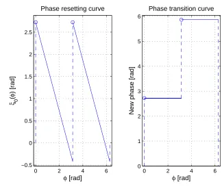
4.6 Example of phase resetting curve and corresponding phase transition curve for the 2-neuron CPG . . . 83
4.7 Example of phase resetting for the 2-neuron CPG by using the PRC shown in fig. 4.6 . . . 83
4.8 Example of phase resetting curve and corresponding phase transition curve for the 2-neuron CPG . . . 84
4.9 Example of phase resetting for the 2-neuron CPG by using the PRC shown in fig. 4.8 . . . 84
4.10 Example of phase resetting curve and corresponding phase transition curve for the 4-neuron CPG . . . 85
4.11 Example of phase resetting for the 4-neuron CPG by using the PRC shown in fig. 4.10 . . . 85
4.12 Example of phase resetting curve and corresponding phase transition curve for the 4-neuron CPG . . . 86
4.13 Example of phase resetting for the 4-neuron CPG by using the PRC shown in fig. 4.12 . . . 86
4.14 Example of phase resetting curve and corresponding phase transition curve for bipedal locomotion . . . 88
4.15 Phase resetting example for the pacemaker oscillator of the network shown in fig. 3.2 . . . 88
4.17 Instant at which the external perturbation is applied to the robot’s
head . . . 90
4.18 Measures provided by the accelerometer located in the robot’s trunk.
The measures are in m
s2. In the plots, the red line represents the system
response when there is no external force applied to the robot’s body.
Thus, the robot is just walking. The blue line represents the behaviour
when the external force is applied to the robot’s head and the phase
resetting controller is not activated. Finally, the green line represents
the behaviour when the phase resetting controller is activated and the
external force is applied to the robot’s head. . . 91
4.19 Output signals of the 4-neuron CPG network shown in fig. 2.15. The
plots represent the system’s response without (top) and with (bottom)
the proposed phase resetting mechanism. . . 92
4.20 System behaviour with phase resetting off. . . 93
List of Tables
2.1 CPG-based locomotion control systems tested on small size humanoid
robots . . . 20
2.2 Internal parameters of Matsuoka’s neurons . . . 25
2.3 Interconnection weights of Matsuoka’s oscillator . . . 25
2.4 Interconnection weights of Matsuoka’s 3-neuron CPG shown in fig. 2.11 28 2.5 Interconnection weights of Matsuoka’s 4-neuron CPG shown in fig. 2.13 28 2.6 Interconnection weights of Matsuoka’s 4-neuron CPG shown in fig. 2.15 28 3.1 CPGs’ interconnection weights . . . 37
3.2 Fixed angles for other joints . . . 43
3.3 Genetic algorithm search space . . . 44
3.4 CPG network parameters found by the GA . . . 45
3.5 CPGs’ interconnection weights . . . 48
3.6 Parameters related to locomotion frequency and stride length for some velocities in accordance with human gait . . . 50
3.7 NAO’s joints with constant angles . . . 51
3.8 Genetic algorithm search space . . . 53
3.9 Optimal parameters of locomotion controllers found by the GA for
several velocities . . . 57
4.1 Interconnection weights of Matsuoka’s oscillator . . . 75
4.2 Interconnection weights of Matsuoka’s 4-neuron CPG . . . 75
4.3 Proportionality constants for the analysed CPG networks and
corresponding coefficients of determination . . . 76
4.4 Parameters of the piecewise phase function for the 2-neuron CPG and
corresponding coefficients of determination . . . 77
4.5 Parameters of the piecewise phase function for the 4-neuron CPG and
CHAPTER
1
Introduction
1.1
Motivation
Biped locomotion has long been of interest to researchers in neuroscience, robotics
and other fields of research. However, the locomotion of legged robots involves
complex dynamic systems from the mechanical, structural and control system
points of view. Many control schemes have been proposed but despite the best
efforts of the scientific community, the problem of biped locomotion has yet to be
satisfactorily solved. At present, interest in humanoid robots is increasing because it
is believed that they will be able to carry out a wide range of functions in the future:
entertainment, dangerous tasks, rescue attempts, helping the disabled (Shukla et al.,
2015), etc. Furthermore, the cost of producing these robots is being reduced, which
is leading to their being used in a variety of scenarios. Many humanoid robots are
now commercially available: for example, ASIMO (Sakagami et al., 2002), NAO
(Gouaillier et al., 2009, 2010), etc.
Humanoid robots are complex electromechanical systems that have been designed
to have the appearance and the main features of human beings so that they can work
and interact in the same environments as they do. The main features of these robots
are the following: they have several degrees of freedom (DoF) so that they can
control the whole body structure (arms, feet, head and trunk). Small humanoid
robots normally use around 22 degrees of freedom to control the whole body and
full-size biped robots use around 40 degrees of freedom. Most of their weight is
located in their upper body and they have only two possible contact surfaces located
on the soles of their feet.
Currently, the study of how legged living organisms move has led to biologically
inspired approaches being applied to the problem of the locomotion of legged
robots because these approaches take advantage of the real, efficient natural process
observed in the locomotor system of living beings. In nature, biological systems
do not perform complex computations and still efficiently solve a wide variety of
complex control problems by using networks consisting of simple units.
Advances in neuroscience have shown clear evidence that rhythms in vertebrate
and invertebrate animals are generated centrally and do not require sensory
information. These rhythms are generated by Central Pattern Generators (CPGs).
These are biological neural networks that can generate complex multi-dimensional
rhythmical signals through the interconnection of mutually inhibiting and excitatory
neurons. CPGs are located in the central nervous system of vertebrates (e.g., cat,
lamprey and human) or in the main ganglia in invertebrates (e.g., leech, worm, and
mollusc Tritonia diomedia) (Yu et al., 2014).
Human locomotion is based on the activity of networks of central pattern
generators. These networks are located in the spinal cord. Afferent information
from the periphery (i.e. the limbs) influences the central pattern and, conversely,
the CPGs select afferent information according to the external requirement. Both
the CPGs and the reflexes that mediate afferent input to the spinal cord are under
Several mathematical models have been proposed to mimic the behaviour
observed in biological CPG networks. These models describe stable rhythmical
output signals that can be easily controlled by using simple input signals which, in
turn, can be used to modulate the CPGs output signals according to the current
external sensory information. Nowadays, the big challenge is to design control
systems inspired by how these networks function to control humanoid robots.
The fact that, in nature, human and animal locomotion is controlled by CPG
networks has inspired the theory on which the present thesis is based. Controlling
the locomotion of biped robots requires a robust control system that can deal with
all the unexpected situations that can arise during motion. The system used by
animals and human beings to control their legs is efficient and adaptive. They can
cope with complex situations and adapt their behaviour to new challenging situations
if required.
1.2
Objectives
1.2.1
General objective
This thesis proposes the use of biologically inspired control approaches to generate
and control the omnidirectional gait of humanoid robots, adapting their movement
on-line to various types of flat terrain using multi-sensory feedback. The main
aim is to design a control strategy that generates and controls well-characterized
locomotion patterns, for humanoid robots with reduced processing capability through
simple but effective control strategies inspired biologically by minimizing the number
of user-tuned, control parameters. The system must guarantee a fast response,
describe well-characterized locomotion patterns comparable to previously proposed
systems, and guarantee correct interaction between the soles of the robot’s feet
and the floor. It should enable the robot to deal with internal mismatches
and external perturbations through feedback strategies that quickly modulate the
well-characterized locomotion pattern. This thesis focuses on the research field of
networks implemented with non-linear oscillators that operate in the joint space.
1.2.2
Specific objectives
The specific objectives of this thesis are listed below:
1. To propose new control schemes based on new networks of non-linear oscillators
and feedback strategies that generate well-characterized patterns to control the
locomotion of biped robots, minimizing the number of control parameters and
avoiding the computation of the inverse kinematics so that response is in real time
even on hardware with low or moderate performance capabilities.
2. To develop an offline methodology that optimizes CPG parameters and
generates omnidirectional gait modes for various types of flat terrain.
3. To propose an online methodology that automatically changes the CPG
parameters and describes omnidirectional movements.
4. To propose an online feedback mechanism that controls the motion described
for the humanoid robot using multi-sensory information that compensates for internal
mismatches and external perturbations.
5. To implement the generation and control locomotion framework in C++ for
the NAO humanoid Robot.
1.3
Overview
The rest of this dissertation is organized as follows:
Chapter 2 introduces some fundamental concepts of biped locomotion and reviews
the relevant literature on control systems used for the locomotion control of humanoid
robots. Finally, some fundamental concepts of CPG networks are presented and the
CPG networks implemented with Matsuoka’s neuron model are studied in detail.
Chapter 3 explains the design methodology used for the study of the two
closed-loop control schemes proposed for the locomotion control of biped robots.
These systems use CPG networks implemented by using Matsuoka’s neuron model to
the proposed control schemes are also presented and discussed.
Chapter 4 presents a detailed description of the phase resetting mechanism
designed for CPG networks based on Matsuoka’s oscillator. Experiments in
simulation and with a real application to closed-loop locomotion control of biped
robots are presented to validate the mechanism. The proposed phase resetting
mechanism is useful for robotics, biomedical and other control applications.
Chapter 5 summarizes the main contributions of this study and proposes some
CHAPTER
2
State of the art
2.1
Biped locomotion
Biped locomotion is a form of terrestrial motion by which an organism changes its
position through the coordinated movement of its rear limbs or legs. There are three
possible types of bipedal locomotion: walking, running and hopping.
During bipedal walking the support leg changes frequently and the contact
surfaces are the soles of the robot’s feet and the floor. The periods of contact are
calledsingle support mode and double support mode. The former is the time during
which the robot is supported on a single foot. The latter is the time during which
both feet are in direct contact with the floor. In bipedal walking the sole of at least
one foot must be in contact with the floor. If there are periods of time during which
both feet leave the ground and there is no direct contact with the walking surface
then the robot is considered to be running.
The walking motion of humanoid robots is commonly produced by the
synchronized movement of its limbs and is usually calculated by solving the inverse
kinematics problem. The motion can also be generated by using models in the Joint
Space to determine the periodic movements that directly control the robot’s joints.
In both cases the motion must guarantee that the robot’s body is stable. These
joints are normally controlled using position, force or parallel force/position control
schemes. To generate stable bipedal walking modes on natural terrain, the complex
dynamic interaction between the robot and the unknown environment around it
must be regulated through the information provided by its sensors. Therefore, this
information needs to be analysed quickly so that loss of balance can be detected and
the system can react as soon as possible.
On flat terrain, the most common concept used to guarantee the stable walking of
a biped robot is the Zero Moment Point (ZMP) (Vukobratovi´c and Borovac, 2004).
This is defined as the point on the ground at which the sum of the moments of
all active forces equals zero. It reduces the representation of the distribution of
the ground reaction forces to a single point. If the ZMP is within the convex hull
(current support polygon) of all the contact points between the feet and the ground,
the gait is dynamically stable. This methodology, first proposed by Vucobratovi´k,
makes it possible to control biped stability using either full (Park and Youm, 2007)
or simplified dynamic models of the humanoid (Kajita et al., 2003).
The normal field of pressure forces for the robot’s feet is equivalent to a single
resultant force exerted at a single point where the resultant moment is zero. This is
known as theCentre of Pressure(CoP). Figure 2.1 shows the graphical representation
of the CoP location. In biped robots, the CoP is estimated by using the measures
provided by the force sensors located in the soles of the robot’s feet. The magnitude
of the resultant force in the normal direction is expressed as:
FRN =
n
X
i=1
FN i, (2.1)
whereFN i is the magnitude of the force provided by theith sensor in the z direction.
F
RNF
NiR
FNiR
CoPCoP
Figure 2.1: CoP location
(normally 8 for biped robots).
The location of the CoP with respect to the base-frame-origin, denoted as RCoP,
can be calculated from:
RCoP=
Pn
i=1RFN iFN i
FRN (2.2)
In humanoid robots with a balanced gait and on flat surfaces, the ZMP coincides
with the CoP. Therefore, the ZMP is commonly calculated by estimating the CoP.
During bipedal locomotion, the body’s weight is continuously changing from one leg
to the other, and the support polygon alternates from single to double support mode
and vice versa. In order for walking to be stable on flat terrain, the ZMP must be
within the polygon described by the current support polygon or the robot will fall.
The centre of masses (CoM) of a humanoid robot is mostly located near the
robot’s chest because it concentrates a large amount of mass. It is very important,
then, to control the robot’s chest position and orientation. Only by doing this can
the location of the CoM also be controlled and balance be provided when unstable
situations arise.
In bipedal locomotion some useful measures of the stability of the motion are:
the static stability margin and the dynamic stability margin. The former is defined
as the minimum distance between the vertical projection of the centre of mass in the
current support polygon and the nearest support polygon’s border to this projection.
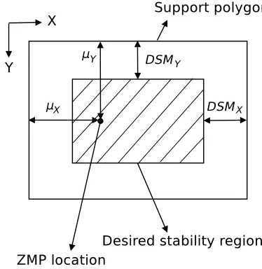
Figure 2.2: Desired dynamic stability margin
must remain inside the current support polygon.
The dynamic stability margin is defined as the minimum distance between the
ZMP and the nearest border of the support polygon. The dynamic stability margin
can be divided into the dynamic stability margin along the sagittal plane, µX, and
the dynamic stability margin along the coronal plane, µY (see fig. 2.2). In order
to guarantee dynamic stability, the ZMP must remain inside the current support
polygon.
The system of locomotion control for biped robots must maximize the stability
margin at all times during motion in order to guarantee a stable walking pose. In
order to guarantee more stable locomotion, a desired stability region is commonly
defined by the values DSMX andDSMY within the support polygon to prevent the
ZMP from being too close to the support polygon’s border. So, the support polygon
is redefined as is shown in fig. 2.2.
In general, locomotion control systems for biped robots must ensure that the
locomotion patterns generated guarantee the stability of the robot’s body during
walking by taking into account the robot’s dynamics and the current interaction
between the soles of the robot’s feet and the terrain through the sensory information.
Therefore, a system that properly and quickly integrates the information extracted
from the current feedback signals is useful because it allows the robot to quickly
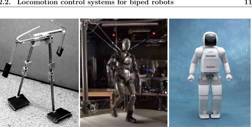
Figure 2.3: Three examples of biped robots. From left to right: Passive Dynamic Walker, Petman and Asimo.
2.2
Locomotion control systems for biped robots
Many control schemes have been proposed in recent years to generate and control the
locomotion of biped robots on flat terrain. These control schemes are mainly designed
to improve one or several of the most important aspects of walking. These aspects
can be summarized as: robustness, versatility and energy efficiency. Robustness
means that the system can cope with large unexpected disturbances that suddenly
appear during motion. If the system is versatile then the control scheme can perform
a wide range of different gaits in different directions, change speed, etc. Finally, an
energy-efficient system attempts to guarantee that the power consumption of the
system is as low as possible.
The specifications of the robot’s hardware also need to be taken into account
because the hardware determines the best control strategy to be implemented. For
instance, if the robot does not have a powerful processor to perform extensive
computations, then a control scheme that takes into account the whole robot’s
dynamics cannot be used. Hence, a control scheme must be implemented that
requires fewer processing capabilities to be properly executed by the robot’s
hardware. Several approaches have been proposed for controlling the robot’s joints
shown in fig. 2.3. For instance, passive dynamic walkers are robots that are designed
to be very energy efficient because the robot’s mechanical structure is carefully built
and naturally conducive to walking (McGeer, 1990). However, they are neither
versatile nor robust and, therefore, it is difficult to use them in real environments.
A control system developed for the biped robot Petman,1
designed by Boston
Dynamics, has proved to be very robust and enables the robot to cope with
considerable external disturbances. However, their results show that the control
system is not very energy efficient or versatile when working in a real dynamic
environment and the implementation seems to be very complex.
Another well-known robot called Asimo (Sakagami et al., 2002), manufactured by
Honda, has been designed to be versatile. It can negotiate different walking surfaces,
make turns, change its walking speed and also run (lift both feet off the ground).
However, it cannot cope with external disturbances or unexpected situations because
it is not very robust.
In general, a control strategy that takes into account the robot’s hardware
resources and the parameters to be improved (robustness, versatility and/or
energy-efficiency) must be defined. The main objective for systems of locomotion
control is to generate reference signals for the robot’s joints, either as angular
displacement or torque, so that motion is stable. These signals are mainly generated
through pre-computed trajectories or trajectories computed in real-time by various
control schemes.
The aim of this thesis is to design a control strategy for humanoid robots with
reduced processing capability that can be versatile and robust. It will use simple
but effective control strategies which take their inspiration from biology and will not
solve the inverse kinematics problem.
Currently, several control strategies have been put forward for solving the biped
locomotion problem. Despite the existence of several types of robots and control
schemes, in this section, only the most common methods in the literature for
generating and controlling the locomotion patterns for biped robots on flat terrain
1
are presented and classified in two categories.
The first category, the ZMP-based control methods, contains the approaches
that use the ZMP location to generate locomotion patterns. To get a real-time
response, these approaches often use a simplified representation of the robot that
employs a simple and easily understandable formulation associated with the model
used. The second category, the biologically inspired control methods, contains all
those control schemes that have been proposed in the literature and which mimic
the efficient functioning of the locomotion control performed by living beings. The
most important feature of biological systems is their adaptability, which makes them
ideal for coping with a variety of situations that can arise during biped locomotion.
2.2.1
ZMP-based control methods
ZMP-based control methods must guarantee that the ZMP remains inside the convex
hull that encloses the support polygon described by the foot or feet that is/are in
contact with the ground. The main inconvenience is that they require precise models
of the robot and the environment, which leads to complex models that require good
hardware specifications so that the calculations can be made for the system to work
in real time. The most commonly used methodology for generating biped locomotion
is a simplified dynamic model of the humanoid robot’s body that describes the
trajectories for the robot’s arms and legs in the task space. These approaches mainly
control the position of the Zero Moment Point (Vukobratovi´c and Borovac, 2004),
track the ZMP location and correct it through a feedback strategy so that the robot’s
balance can be recovered if necessary.
One of the most used models is the mass concentrated model. It simplifies
the whole body dynamics to the centre of gravity motion by concentrating the
whole-body mass at that point. It is the most suitable model for real-time
applications, because it computes the walking motion faster. Two kinds of
mass concentrated models have been used for attaining stable walking: the three
dimensional linear inverted pendulum model (3D-LIPM) and the cart-table model
analysing the dynamics of the motion of a three dimensional linear inverted pendulum
model on an arbitrarily defined plane (Sugihara et al., 2002; Kajita et al., 2002). The
3D-LIPM models the humanoid robot motion by computing a smooth trajectory of
a single mass (centre of mass), which follows the inverted pendulum laws under the
gravity field; the constraint is to maintain the ZMP on the support polygon during
walking in order to prevent the humanoid from falling down. Therefore, a stability
controller for recovering balance is required to deal with internal mismatches and
external perturbations.
In (Choi et al., 2007), a CoM/ZMP trajectory planning method with a humanoid
simplified model was proposed to generate the stable movement for a humanoid
robot. To guarantee the stability of the motion, a walking CoM/ZMP controller is
used. Using the full dynamic model, an on-line pattern generator for bipedal walking
control can be designed based on a ZMP preview control (Park and Youm, 2007).
However, a humanoid robot with a good processing capability is required.
2.2.2
Biologically inspired control methods
Getting biped robots to walk requires a robust control system that can cope with a
wide variety of unexpected events in real time. In recent years, biologically inspired
control approaches have successfully been used to generate and control the motion
of various types of robots (Bekey, 2005). These approaches have proven to be simple
yet robust and reliable. This is due to the fact that animals and human beings do not
solve complex formulations to generate movements and can react easily to changes
in the environment.
Many of the behaviours currently studied by neuroscientists are rhythmic. If a
behaviour is rhythmic, there will be many repetitions of very similar movements.
Many rhythmic behaviours such as walking are generated by a specialized subset of
neurons that control these behaviours. These neural networks can usually generate
rhythmic patterns without outside stimuli; that is, the rhythm is intrinsic to the
network and/or cells of the network. These networks are called Central Pattern
robots because they generate rhythmic signals easily by using simple input signals.
Furthermore, the oscillations generated are stable and can be easily modulated to
incorporate feedback.
The first studies about CPGs applied to biped locomotion were presented in
(Taga et al., 1991; Taga, 1995), who investigated the use of CPGs for controlling
the walking of a simulated humanoid robot on a 2D plane. The results showed
that the CPG controller was robust to disturbances. In (Miyakoshi et al., 1998),
the previous work was extended to 3D using a simplified model without arms or
head. The results showed that it is possible to obtain a stable biped stepping
motion and tolerance against external perturbations with a neural oscillator system.
Unlike ZMP methodologies, bipedal locomotion based on CPGs does not require
precise information about the environment. The CPG-based controllers interact with
biomechanical and environmental constraints through sensory feedback to adapt to
changes and learning. Endo et al. (2004) investigated the robustness of the CPG
controllers for a walking robot. The robot does not have an upper body and it is
supported by a boom, which helps with balancing. Subsequently, they applied a
CPG controlled with biologically inspired feedback to control the humanoid robot
QRIO. Experimental results show that this controller is robust to perturbations and
environmental changes (Endo et al., 2005). CPGs with sensory feedback play an
important role and provide a promising way to develop robust humanoid walking
control, and efficient coupling between the robot and the environment.
Artificial CPGs can be used to control the robot’s motion in either the task space
(Liu et al., 2013b; Song and Hsieh, 2014) or the joint space (Nassour et al., 2013).
The first approach aims at determining the Cartesian space trajectories of the robot’s
limbs. In this case, the individual signals for the robot’s joints must be generated
by solving the inverse kinematics, which is a time-consuming process. Alternatively,
if motion is generated in the joint space, the CPG output signals are directly used
to control the angular position of the robot’s joints. Later, some of the main studies
in the literature for CPG-based control systems are presented in order to summarize
Figure 2.4: CPG-task-space control
the use of CPG-based control systems to generate closed-loop locomotion patterns
for biped robots.
2.2.2.1 CPG-task-space control methods
Figure 2.4 presents the block diagram for a CPG-task-space control scheme. The
signals generated by the CPG network are modulated through the feedback signals
obtained by analysing the current sensory information provided by the robot’s
sensors. The aim is to control the limb trajectories in the Cartesian space. Therefore,
the angular position of the robot’s joints must be calculated by solving the inverse
kinematics problem. Some of the studies in the literature on the locomotion control
of biped robots in the CPG-task-space are presented below.
A CPG network that generates the stepping and propulsive motion for locomotion
control of a biped robot was proposed in (Endo et al., 2008). The feedback pathways
for propulsive motion were obtained through a gradient method, by using the pelvis
angular velocity in the sagittal and coronal planes as inputs to generate a feedback
signal that controls the trajectory of the legs in the direction of walking. Results on
flat terrain were reported. Alternatively, a control system that generates the motion
of a biped robot in the task-space by using nonlinear oscillators was presented in
Figure 2.5: CPG-joint-space control
provided by touch sensors. Later, in (Aoi and Tsuchiya, 2007), the same authors
extended their previous work to controlling the turning behaviour of the biped robot.
A pattern generator based on coupled oscillators is used in (Ha et al., 2011). The
system is compensated directly with the data provided by the inertial sensors without
real-time estimation of the current ZMP. In (Liu et al., 2013b), a CPG network is
used to describe and modulate the trajectory of the robot’s centre of gravity and, as
a result, the trajectories of its limbs in the workspace. Experiments show that the
robot can walk on both flat and inclined terrain with slopes of +/-10 degrees.
To generate stable static walking, Song and Hsieh (2014) proposed a pattern
generator system for biped locomotion based on CPG networks. The system
compensates for the slope of terrain with the pose of the upper-body’s centre of
gravity. The authors claim that the robot can walk on flat and inclined terrain with
slopes of +/-7 degrees.
2.2.2.2 CPG-joint-space control methods
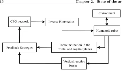
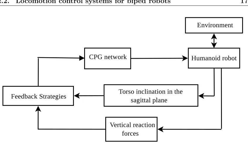
Figure 2.5 shows the block diagram of a CPG-joint-space control scheme. The signals
generated by the CPG network are modulated through feedback signals obtained by
system aims at controlling the angular position of the robot’s joints directly with the
output signals of the network. Some of the studies proposed in the literature for the
locomotion control of biped robots in the CPG-joint-space are summarized below.
A CPG implemented with coupled nonlinear oscillators was proposed in (Righetti
and Ijspeert, 2006) to control the biped locomotion of a humanoid robot. The
system learns an arbitrary signal in a supervised framework. It modulates
some parameters and introduces feedback signals provided by the robot’s sensors.
However, locomotion patterns must be defined in advance. In (Morimoto et al.,
2008), the signals for the robot’s joints are generated by using coupled oscillator
models based on sensory information about the location of the centre of pressure
and its velocity. Results on flat terrain were reported.
In turn, (Matos and Santos, 2012) proposed a feedback mechanism for phase
regulation using load sensory information. The signals for the motors are specified
in the joint-space through mathematical formulations that define the angular
displacement, and the parameters that characterize the system’s behaviour are
hand-tuned. Subsequently, (Oliveira et al., 2013) proposed a multi-objective staged
evolutionary algorithm to find the parameters that characterize the open-loop
behaviour of the system. However, because the genetic algorithm used a reduced
number of individuals and a hand-tuned gait was included as an individual in a
random initial population, thus biasing the final convergence, there is no guarantee
that the algorithm ends up exploring the whole search space or that it finds all the
feasible solutions. The control system was tested on flat and sloped terrain with
a maximum ascending slope of 4 degrees and a maximum descending slope of 2.5
degrees.
(Nassour et al., 2013) proposed a control scheme for qualitative adaptive reward
learning with success failure maps applied to humanoid robot walking. However,
their technique does not ensure stable interaction with the floor, since the robot
tends to drag its feet when walking, which is likely to lead to falls on uneven terrain.
The authors present results with the NAO walking on slopes of +/-10 degrees.
locomotion control of biped robots that have been successfully tested on small-size
humanoid robots. All these approaches have been inspired by biological CPG
networks.
2.2.2.3 Estimation of CPG network parameters through genetic
algorithms
Genetic Algorithms have been used to determine the best combination of parameters
that characterize the behaviour of CPG networks and to find the optimal set of
parameters for the control system of various types of robots.
These algorithms are inspired by the mechanism of natural selection and natural
genetics observed in nature. They use three basic operators to find the individuals
with the highest fitness value according to the fitness function defined. These
operators are: selection, crossover and mutation (Passino, 2004). In order to
determine the best combination of parameters it is important that the fitness function
used in the genetic algorithm assesses, sorts and classifies the individuals in each
epoch in order to guarantee correct evolution over time.
In (Inada and Ishii, 2003), a five-step genetic algorithm is proposed for
determining the optimal 271 parameters for a system for generating motion that
uses a CPG network that describes an optimal locomotion pattern for a biped robot.
(Kamimura et al., 2005) proposes a genetic algorithm to determine the optimal
interconnection weights and the initial values for the variables of the CPG networks
used to control the straight-line locomotion of a modular robotic system. In order to
determine the system parameters for controlling the locomotion of a quadruped robot
a genetic algorithm is used in (Liu et al., 2013a). The algorithm finds the weight of
the interconnections between oscillators to generate appropriate phase relationships
and realize the animal-like walking pattern. A bio-inspired system for controlling
the locomotion of a biped robot based on Central Pattern Generators (CPGs) is
proposed in (Oliveira et al., 2013). A multi-objective evolutionary algorithm is used
to search for the best set of optimized CPG parameters through multiple objectives
C
h
a
p
te
r
2.
S
ta
te
of
th
e
a
r
t
S. Aoi Coupled oscillators Phase resetting Flat terrain HOAP-1 2005
Aoi and Tsuchiya (2005) (task space) through the impact instant
J. Morimoto Coupled oscillators CoM used for modulation Flat terrain Qrio 2008
Morimoto et al. (2008) (joint space) of phase resetting Maximum obstacle height of 3.5mm
H. Inyong Coupled oscillators Balance controller Flat terrain Darwin 2011
Ha et al. (2011) (task space) through torque compensation
V. Matos Coupled oscillators Phase regulation Flat terrain
Matos and Santos (2012) (joint space) Maximum ascending slope of 4 degrees Darwin 2012
Maximum descending slope of 2.5 degrees
C. Liu CPG-task space control Modulation of Flat terrain
Liu et al. (2013b) (task space) the CoM trajectory Maximum ascending slope of 10 degrees Nao 2013 Maximum descending slope of 10 degrees
J. Nassour Neurobiological-inspired Inertial sensor used Flat terrain
Nassour et al. (2013) learning algorithm to adjust the centre of Maximum ascending slope of 10 degrees Nao 2013 (joint space) oscillation of ankle joints Maximum descending slope of 10 degrees
K. Song CPG-task space control Posture controller Flat terrain
Song and Hsieh (2014) (task space) Maximum ascending slope of 7 degrees Nao 2014
Maximum descending slope of 7 degrees
Proposed approach CPG-joint space control Posture controller Flat terrain
2.3
Central pattern generators
Central pattern generators are biological neural networks that can control
coordinated movements, such as those involved in locomotion, respiration, chewing
or swallowing. CPGs are able to generate rhythmical signals without any external
sensory input, since they oscillate depending on the value of internal parameters and
the interconnection weights between neurons. One of the most attractive features
of CPGs is their ability to adapt the oscillations generated to external conditions
by modulating the oscillatory parameters (i.e., frequency, amplitude, phase) from
external feedback signals provided by a sensory subsystem. These features make the
networks suitable for controlling the locomotion of humanoid robots.
2.3.1
Introduction
Advances in neuroscience have revealed the biological functioning of the locomotor
system in humans and animals. This is an area in which neuroscience and
robotics can complement each other. A wide variety of biologically-inspired control
architectures have been studied in recent decades for closed-loop motion control
of mobile robots, and most of them mimic the functionality of CPGs (Ijspeert,
2008; Yu et al., 2014). CPG-based models have interesting properties and may
be an alternative to the classical methods proposed in the literature for controlling
locomotion in robots (i.e., ZMP-based control, finite-state machines). CPG networks
have been used to successfully control several types of robots (i.e., legged robots
(Kimura et al., 2007), snake-like robots (Crespi and Ijspeert, 2008), salamander-like
robots (Bicanski et al., 2013), reconfigurable robots (Kamimura et al., 2005), etc.).
Some of the most important properties of CPGs are listed below:
• CPG models produce stable rhythmic patterns with stable limit cycles.
• The system based on CPG networks can be characterized by a reduced number
of parameters which enable the system to generate multidimensional output
signals with simple control signals.
modulating their parameters from feedback signals provided by the sensors so
that the system’s current state can be changed and synchronized in accordance
with the real-time sensory information.
• Control systems based on CPG networks can use optimization (e.g., genetic
algorithms) and learning algorithms (e.g., policy gradient method).
However, a global design methodology for developing CPG-based control systems
has not been defined to get an optimal control system. The list below provides some
important tips for designing a CPG-based control system:
• Determine the general architecture of the CPG-based control system by
defining how the CPG network is going to be used inside the control loop.
• Design the CPG network topology and define the number of neurons. The
topology depends on the number of outputs and the waveforms required by
the system.
• Study how modulating the input signals and/or varying the CPG’s internal
parameters affects the CPG’s output signals. The goal is to introduce feedback
signals that can quickly adapt the activity of the CPG network to the
real-time sensory information. It is very important to incorporate useful and
well-characterized feedback controllers.
Many mathematical models have been proposed to model the neuron’s dynamic
response and build a CPG network of interconnected neurons. For instance, networks
based on phase oscillators defined by systems of equations, which represent the phase
behaviour, are used to directly control the phase of output signals by advancing or
delaying their value (Aoi and Tsuchiya, 2007; Matos and Santos, 2012; Endo et al.,
2004).
In this thesis a well-known neuron model proposed by Matsuoka (1985, 1987)
is used to build the CPG networks. This model has been used in several studies
because of its interesting properties (Taga et al., 1991; Park et al., 2010; Liu et al.,
2011; Kimura et al., 2007; Huang et al., 2008; Kamimura et al., 2005; Endo et al.,
2005, 2008; Zhang et al., 2011). Furthermore, Matsuoka’s model makes the hardware
and Matsuoka, 2012). In CPG networks based on Matsuoka’s model the oscillations
are generated by the mutual inhibition of neurons which are represented by a
continuous time variable model with a kind of fatigue or adaptation effect (see below).
2.3.2
Matsuoka’s oscillator
The simplest CPG model proposed by Matsuoka (1985, 1987, 2011) is a non-linear
oscillator that has widely been applied to robotic systems because it is at once
simple and effective. It consists of two tonically excited neurons with a self-inhibitory
effect, which are reciprocally linked via inhibitory connections. The block diagram of
Matsuoka’s oscillator can be seen in fig. 2.6 and its simplified representation in fig.
2.7. The system of equations that characterizes the behaviour of each neuron enables
the amplitude, shape and frequency of the output signals generated to be controlled.
Matsuoka’s neuron model is used to build a neural network of N interconnected
neurons, with the i-th neuron being defined by two differential equations with two
state variables,ui, vi, and a single output, yi:
τui˙ =−ui− N
X
j=1
wijyj −βvi+ue+fi (2.3)
τ′vi˙ =−vi+yi
yi = max(0, ui).
The amplitude of the neuron’s output signal can be controlled through the
external input ue. The frequency of the output signals is determined by the values
of τ, τ′, wij and β. Term fi is a feedback variable that can be used to control the
output amplitude and synchronize the output signals with a periodic input signal by
using the entrainment property of CPGs. In this way, this feedback variable adapts
the behaviour of the neuron to external sensory stimuli. A detailed explanation
of the entrainment property can be found in (Williamson, 1999). The weighting
coefficients wij represent the bidirectional connection weights between the i-th and
Inhibitory connection
[image:45.595.179.392.110.434.2]Excitatory connection
Figure 2.6: Schematic representation of Matsuoka’s non-linear oscillator
signals of the interconnected neurons. All neurons within the network oscillate
synchronously according to their internal parameters and network connections,
converging to specific patterns and limit cycles. All constant parameters must satisfy
certain constraints if oscillations are to be stable (Matsuoka, 1985, 2011).
In order to modulate the frequency of the output signal, Zhang et al. (2011)
introduced an additional parameter, Kf, such that the time constants in (2.3) are
reformulated as:
τ =τoKf τ′ =τ′
oKf, (2.4)
where τo and τ′
o are the original time constants.
For Matsuoka’s oscillator, after the mathematical expression of angular velocity
Table 2.2: Internal parameters of Matsuoka’s neurons
Parameter Value Parameter Value
τo 0.2800 ue 0.4111
τ′
o 0.4977 fi 0
β 2.5000
Table 2.3: Interconnection weights of Matsuoka’s oscillator
w1,2 2 w2,1 2
Figure 2.7: Simplified topology of 2-neuron Matsuoka’s CPG (Matsuoka’s oscillator)
the output signal can be expressed as:
Γ(Kf)≈ 1
2πKf
r
1+(β
w−1)
τo τ′o+1
τoτo′ . (2.5)
As is demonstrated in (Matsuoka, 2011), an oscillator generates a stable
oscillation if the condition below is fulfilled:
1 + τ
τ′ < w < 1 +β. (2.6)
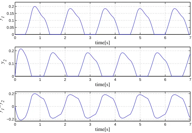
The output signals generated by Matsuoka’s oscillator with the parameters in
tables 2.2 and 2.3 are shown in fig. 2.8. These parameters and weights were
experimentally chosen in this thesis to yield output signals that resembled as closely
as possible a sinusoidal wave. The value used for variable Kf was 0.7. In this
case, there is no modulation of the oscillator’s internal parameters. Figures 2.9 and
2.10 show examples of output signals obtained by varying the oscillator’s internal
parameters ue and Kf, respectively. In fig. 2.9, the value used for variable Kf was
0 1 2 3 4 5 6 7 0 0.05 0.1 0.15 0.2 y 1 time[s]
0 1 2 3 4 5 6 7
0 0.1 0.2
y 2
time[s]
0 1 2 3 4 5 6 7
−0.2 0 0.2 y 1 −y 2 time[s]
Figure 2.8: Output signals of Matsuoka’s oscillator
0 1 2 3 4 5 6 7
0 1 2 3 ue time[s]
0 1 2 3 4 5 6 7
[image:47.595.123.438.127.345.2]−1 −0.5 0 0.5 1 y 1 −y 2 time[s]
Figure 2.9: Example of amplitude modulation by varying parameterue
signals and gives a quick system response. As a result, the amplitude and frequency
of the output signals generated adapt quickly. There is no suitable control strategy
for specifying the phase of the output signals in real time. Therefore, in chapter 4 a
control mechanism is proposed and validated for modifying the phase of the output
signals generated by Matsuoka’s oscillator or networks based on Matsuoka’s neuron
0 1 2 3 4 5 6 7 0
0.1 0.2 0.3
Kf
time[s]
0 1 2 3 4 5 6 7
−0.2 −0.1 0 0.1 0.2
y 1
−y
2
time[s]
Figure 2.10: Example of frequency modulation by varying parameterKf
2.3.3
CPG networks based on Matsuoka’s neuron model
This section presents some examples of oscillations generated by CPG networks
based on Matsuoka’s neuron model. Figures 2.11, 2.13 and 2.15 show CPG network
topologies proposed by Matsuoka and figs. 2.12, 2.14 and 2.16, respectively, show
their corresponding output signals. The connection weights are shown in tables
2.4, 2.5 and 2.6. These weights were experimentally chosen in this thesis to yield
output signals that resembled as closely as possible a sinusoidal wave. The output
signals shown in these figures show the stable rhythmic patterns generated by each
neuron. This feature makes these networks useful for control applications that require
rhythmical signal within their control scheme.
Some of the CPG networks proposed by Matsuoka have been widely used in
mobile robotics and other control applications because they are simple and effective
(e.g., Endo et al., 2005, 2008; Zhang et al., 2011; Xu et al., 2009). Other topologies
of CPG networks based on Matsuoka’s neuron model have also been proposed for
the locomotion control of mobile robots (e.g., Taga et al., 1991; Park et al., 2010;
Liu et al., 2011; Kimura et al., 2007; Huang et al., 2008; Kamimura et al., 2005;
Cristiano et al., 2013).
For instance, Kimura et al. (2007) proposed a system for the adaptive dynamic
walking of a quadruped robot on natural ground by means of a control scheme based
on a CPG network implemented with Matsuoka’s neuron model. (Kamimura et al.,
N1
N2 N3
Figure 2.11: CPG network of 3 neurons as proposed in (Matsuoka, 1985)
controller that uses CPG networks based on Matsuoka’s neuron model which is
suitable for all modular robots.
Table 2.4: Interconnection weights of Matsuoka’s 3-neuron CPG shown in fig. 2.11
w1,1 0.0 w1,2 0.0 w1,3 2.5 w2,1 2.5 w2,2 0.0 w2,3 0.0 w3,1 0.0 w3,2 2.5 w3,3 0.0
Table 2.5: Interconnection weights of Matsuoka’s 4-neuron CPG shown in fig. 2.13
w1,1 0.0 w1,2 0.0 w1,3 0.0 w1,4 2.5 w2,1 2.5 w2,2 0.0 w2,3 0.0 w2,4 0.0 w3,1 0.0 w3,2 2.5 w3,3 0.0 w3,4 0.0 w4,1 0.0 w4,2 0.0 w4,3 2.5 w4,4 0.0
Table 2.6: Interconnection weights of Matsuoka’s 4-neuron CPG shown in fig. 2.15
0 1 2 3 4 5 6 7 0 0.1 0.2 y 1 time[s]
0 1 2 3 4 5 6 7 0
0.1 0.2
y 2
time[s]
0 1 2 3 4 5 6 7 0
0.1 0.2
y 3
time[s]
Figure 2.12: Output signals of the 3-neuron CPG shown in fig. 2.11
N1
N2 N3
N4
Figure 2.13: 4-neuron CPG network as proposed in (Matsuoka, 1985)
0 1 2 3 4 5 6 7
0 0.1 0.2
y1
time[s]
0 1 2 3 4 5 6 7
0 0.1 0.2
y2
time[s]
0 1 2 3 4 5 6 7
0 0.1 0.2
y3
time[s]
0 1 2 3 4 5 6 7
0 0.1 0.2
y4
time[s]
Figure 2.15: 4-neuron CPG network as proposed in (Matsuoka, 1985)
0 1 2 3 4 5 6 7
0 0.1 0.2
y 1
Time[s]
0 1 2 3 4 5 6 7
0 0.1 0.2
y 2
Time[s]
0 1 2 3 4 5 6 7
0 0.1 0.2
y 3
Time[s]
0 1 2 3 4 5 6 7
0 0.1 0.2
y 4
Time[s]
CHAPTER
3
Proposed systems for locomotion control of
biped robots
In this chapter, two CPG-joint-space control schemes are proposed to control the
locomotion of biped robots by using rhythmical signals generated by Central Pattern
Generator (CPG) networks based on Matsuoka’s neuron model. Previous approaches
require a large number of parameters to characterize the generation and control of
the locomotion pattern. Thus, the first control scheme proposed here was designed
to have a reduced number of parameters and to be able to deal with obstacles on
the walking surface.
The main features that a CPG-joint-space control system must have for the
locomotion control of humanoid robots have also been identified. The system must
generate a well-characterized locomotion pattern that can easily be modulated by
the feedback signals provided by the robot’s sensors and that guarantees a correct
interaction between the robot’s feet soles and the floor. Genetic algorithms are used
in this research to determine the combination of CPG network parameters that is
best for generating optimal locomotion patterns for a defined fitness function. The
systems proposed for the locomotion control of biped robots were tested by simulation
and with a real humanoid robot.
The second control scheme proposed in this chapter was designed using the results
obtained with the first control scheme. The aim was to define a system that generates
well-characterized and optimal locomotion patterns that can be easily modulated
and which guarantee correct interaction between the soles of the robot’s feet and
the floor. This has been identified as the main drawback of CPG-joint-space based
control schemes because the signal generation process of the locomotion pattern is not
easy to understand and the integration of new feedback signals to deal with complex
situations is cumbersome. Also, the interaction between the soles of the robot’s feet
and the floor is not good enough, which limits the practical application of these
approaches. Therefore, the locomotion pattern needs to interact properly with the
floor, so that the system can control the real-time locomotion pattern described by
the robot and cope with more complex situations.
Similar CPG-based systems for locomotion control of biped robots tested on
sloped surfaces have previously been proposed in the literature. However, the most
robust of those previous approaches need to solve the costly inverse kinematics
(Liu et al., 2013b; Song and Hsieh, 2014), whereas the other approaches do not
guarantee stable interaction with the floor, since the robot tends to drag its feet
when walking, which is very likely to lead to falls on uneven terrain (Nassour
et al., 2013). The results show that the proposed system, like the state-of-the-art
for CPG-based control systems, can negotiate sloped surfaces (see table 2.1) and
also generate well-characterized omnidirectional locomotion patterns that guarantee
correct interaction with the floor.
Since the proposed control scheme is well-characterized, it can be incrementally
improved by adding more controllers that allow the robot to deal with more complex
guarantees the system’s quick response and also makes it especially suitable for direct
hardware implementation with electronic circuits.
3.1
Introduction
The systems that control the locomotion of biped robots must naturally integrate
three fundamental aspects: the robot’s body, the environment and the control
system. Such a control system basically consists of two main stages. The first
stage generates the locomotion pattern, whereas the second introduces feedback into
the system in order to modulate the current locomotion pattern so that stability can
be recovered whenever unexpected situations appear as the robot is walking.
3.1.1
NAO humanoid robot
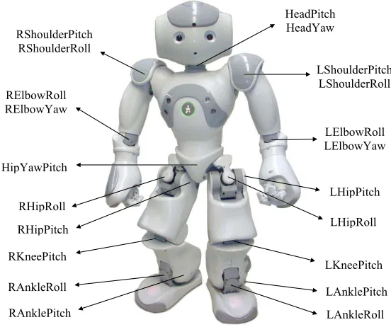
The proposed control schemes were validated in a NAO humanoid robot (Gouaillier
et al., 2009, 2010). However, these can be easily adapted to other biped robots
with a similar kinematic structure of joints after making the corresponding changes
(robot model, limits for the genetic algorithm search space, etc.). NAO is a small-size
humanoid 56 cm tall and weighing 4.8 kg. It has 21 degrees of freedom (1 for the
pelvis, 5 for each leg, 2 for the head and 4 for each arm) (see fig. 3.1). It is also
equipped with two cameras, an inertial measuring unit (2-axis gyrometer with 5%
precision with an angular speed of 500◦/s and 3-axis accelerometer with 1% precision
with an acceleration of 2g), four sonars and four force sensors under each foot. The
force sensors measure the change in resistance depending on the pressure applied
and have a working range from 0 N to 25 N. These force sensors and their position
are used to determine the CoP location (see section 2.1).
The motion of the robot’s joints is performed through a joint position
control-loop. Magnetic rotary encoders (MRE) are used to estimate the motors’
angular position. The motors used in the NAO are Maxon coreless brush DC motors.
There are two classes, with their respective reduction gears, which are driven by