A Numerical Approach based on the BEM for Computing
Transferred Earth Potentials in Grounding Analysis
I. Colominas, F. Navarrina and M. Casteleiro
Group of Numerical Methods in Engineering, GMNI
Civil Engineering School, University of Coru˜na,
Campus de Elvi˜na, 15192 A Coru˜na, SPAIN
e-mail: [email protected], web: http://caminos.udc.es/gmni/
Key words: Boundary Element Method, Transferred Earth Potentials, Grounding Analysis
Abstract
In this paper we present a numerical approach based on the Boundary Element Method for the analysis
of a very common problem in electrical engineering practice: the existence of transferred earth potentials
in a grounding installation [1]. We propose a numerical approach to analyze this phenomenum. We
demonstrate its feasibility by means of an application example with the geometry of a real grounding
1 Mathematical and Numerical Model of the Electrical Current Dissipation into a Soil
The main goals of a grounding system are to guarantee the integrity of equipment and the continuity of
the service under fault conditions and to safeguard that persons working or walking in the surroundings
of the grounded installation are not exposed to dangerous electrical shocks. Consequently, the apparent
electrical resistance of the earthing system must be low enough to assure that fault currents dissipate
mainly through the grounded electrode, while maximum potential differences between close points on
the earth surface must be kept under certain tolerances (step, touch and mesh voltages) [1].
In the last four decades, the operation of grounding systems has been extensively analyzed, and several
methods for analysis and design have been proposed. Most of these methods are based on the
profes-sional experience, on semi-empirical works, on experimental data obtained from scale model assays and
laboratory tests, or on intuitive ideas. These contributions represented an important improvement in the
grounding analysis area; however, some problems have been systematically reported, such as the large
computational costs required in the analysis of real cases, the unrealistic results obtained when
segmen-tation of conductors is increased, and the uncertainty in the margin of error [1, 2, 3].
The electrical current dissipation into the soil is a well-known phenomenum which equations can be
stated from Maxwell’s Electromagnetic Theory. Thus, restricting the analysis to the electrokinetic
steady-state response and neglecting the inner resistivity of the earthing conductors, the 3D problem is
div(σσσσσσσσσσσσσσ) = 0; σσσσσσσσσσσσσσ=−γγγγγγγγγγγγγγgrad(V)inE; σσσσσσσσσσσσσσtnnnnnnnnnnnnnnE = 0inΓE; V =VΓinΓ; V →0, if|xxxxxxxxxxxxxx| → ∞ (1)
whereE is the earth,γγγγγγγγγγγγγγ is its conductivity tensor,ΓE is the earth surface,nnnnnnnnnnnnnnE is its normal exterior unit
field andΓis the electrode surface [4]. Therefore, the solution to (1) gives the potentialV and the current densityσσσσσσσσσσσσσσat an arbitrary pointxxxxxxxxxxxxxxwhen the electrode attains a voltageVΓ(Ground Potential Rise, or GPR)
In the last years, the authors have proposed a numerical approach based on the BEM to solve problem
(1) in the case of grounding grids of large electrical installations (generally, a mesh of interconnected
bare conductors with a relatively small ratio diameter-length). These numerical formulations were
orig-inally developed for grounding grids embedded in uniform soil models [4], which have been recently
generalized for layered soil models [5]. From this general approach, it has been possible to derive
spe-cific numerical formulations of high accuracy [4], and to explain from a mathematical point of view the
anomalous asymptotic behaviour of the classical methods proposed for grounding analysis, identifying
rigorously the sources of error [3].
The starting point of these numerical approaches is the transformation of the 3D problem given by (1)
onto an integral problem which unknown function is defined in the boundaries of the domain, i.e., the
electrode surface Γ. The techniques presented in this paper can be extended to layered soil models,
and our objective is to analyze the problem of the transferred potentials in grounding systems. Thus,
we will consider the simplest soil model, that is, the homogeneous and isotropic soil model. Then, the
conductivity tensorγγγγγγγγγγγγγγ is substituted by an scalar conductivity γ. Thus, the application of the “method of images” and Green’s Identity yields the following integral expression [4] for the potential V at an arbitrary point xxxxxxxxxxxxxx ∈ E, in terms of the unknown leakage current density σ(ξξξξξξξξξξξξξξ) at any point ξξξξξξξξξξξξξξ of the electrode surfaceΓ⊂E(σ=σσσσσσσσσσσσσσtnnnnnnnnnnnnnnbeingnnnnnnnnnnnnnnthe normal exterior unit field toΓ):
V(xxxxxxxxxxxxxx) = 1 4πγ
Z Z
ξξξξξξξξξξξξξξ∈Γ
k(xx, ξξξξξξξξξξξξξξxxxxxxxxxxxx )σ(ξξξξξξξξξξξξξξ)dΓ, k(xxxxx, ξξξξξξξξξξξξξξxxxxxxxxx ) = 1 |xxxxxxxxxxxxxx−ξξξξξξξξξξξξξξ| +
1
|xxxxxxxxxxxxxx−ξξξξξξξξξξξξξξ0| (2) whereξξξξξξξξξξξξξξ00000000000000is the symmetric ofξξξξξξξξξξξξξξwith respect to the earth surface [4]. Now, since expression (2) also holds onΓ, where the potential is known (V(χχχχχχχχχχχχχχ) =VΓ,∀χχχχχχχχχχχχχχ∈Γ), the leakage current densityσmust satisfy an
integral equation, which variational form is Z Z χ χ χ χχχχ χ χ χχχ χ χ∈Γ
w(χχχχχχχχχχχχχχ) "
VΓ−4πγ1
Z Z
ξξξξξξξξξξξξξξ∈Γ
k(χχ, ξξξξξξξξξξξξξξχχχχχχχχχχχχ )σ(ξξξξξξξξξξξξξξ)dΓ #
for all membersw(·)of a class of test functions defined onΓ[4].
Next, for given sets ofN trial functions{Ni(ξξξξξξξξξξξξξξ)}defined onΓandM boundary elements{Γα}, we can discretize the leakage current densityσand the electrode surfaceΓ:
σ(ξξξξξξξξξξξξξξ)≈σh(ξξξξξξξξξξξξξξ) =
N
X
i=1
Ni(ξξξξξξξξξξξξξξ)σi, Γ = M [
α=1
Γα, (4)
and it is also possible to obtain a discretized version of expression (2). On the other hand, for a given
set ofN test functions{wj(χχχχχχχχχχχχχχ)}defined onΓ, the variational form (3) can be written in terms of a linear system of equations:
N
X
i=1
Rjiσi =νj j= 1, . . . ,N, (5) which solution provides the values of the unknownsσi that are necessary to compute the potential V at any point xxxxxxxxxxxxxx. In the references [4, 5], the whole development of the numerical formulation based on the BEM for uniform and layered soil models can be found, as well as a fully explicit discussion
about the main numerical aspects of the BEM numerical approaches. The result is a numerical technique
mathematically and numerically well-founded, and highly efficient from a computational point of view.
Next, we propose to solve the problem of trasferred earth potentials in grounding systems by means of
these BE techniques.
2 Analysis of Transferred Earth Potentials and Application Example
Transferred earth potentials refer to the phenomenon of the earth potential of one location appearing
at another location where there is a certain earth potential. Specifically, during a fault condition the
grounding grid of an electrical substation attains a voltage (GPR) which can be in the order of thousands
of volts. This voltage (or a fraction of it) may be transferred out to a non-fault site by a ground conductor
(such as metal pipes, rails, metallic fences, etc.), and it may produce serious hazards to the personnel,
Generally, there are two main cases of transferred potentials: I) the transference of the GPR to distant
points by a conductor directly linked to the earthing system; and II), the transference of a fraction of the
GPR to distant points by means of conductors close to the earthing grid but not directly connected to it.
In both cases, the potential distribution on the earth surface will be significantly modified.
The analysis of transferred potentials in case I) does not imply a significantly change in the numerical
approach, since the extra-conductors are formally part of the grounding grid, and they must be included
in the earthing analysis as part of the grid.
Case II) is more difficult to deal with, because the extra-conductors attain an unknown voltage (i.e., a
fraction of the GPR) due to their closeness to the grounding grid when a fault condition occurs. Then, our
main objectives are to obtain this voltage and the potential distribution on the earth surface. Thus, if we
call as “active grid” the electrodes which form the grounding grid (energized to the GPR) and “passive
grid” the extra-conductors (which attain a fraction of the GPR) not connected to the grounding grid, the
analysis of transferred potentials from an “active grid” (e.g., the left grid of Figure 1) to a “passive grid”
(e.g., the right one of Figure 1) can be performed by means of a superposition of elementary states.
The two elementary states we can consider are the following: state 1) the “active grid” energized to 1 V
and the “passive grid” to 0 V; and state 2) the “active grid” energized to 0 V and the “passive grid” to
1 V. With these values of unitary GPR, we can apply the BEM numerical approach presented to each
elementary state, and to obtain the total electrical current by unit of voltage which flows from each grid.
On the other hand, the final state is the “active grid” energized to the GPR (e.g., 10 kV) and the “passive
grid” energized to a fractionλof the GPR (e.g.,10λkV). Due to the linear character of the problem to solve, this final state can be obtained by linear combination of the elementary states (state 1) weighted
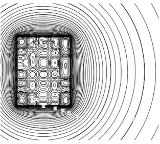
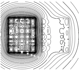
Once the fractionλof the GPR is known in the “passive grid”, it is possible to compute the potential distribution on the earth surface, and consequently, obtaining the touch and step voltages in all points of
the substation site and in its surroundings. In Figure 2, it is shown the potential distribution on the earth
surface if the “passive grid” is not considered, and in Figure 3 it is shown the potential distribution if this
grid is considered. Note the important differences between both results and the appearance of potential
gradients in (at first) non-expected areas.
3 Conclusions
In this paper, we have summarize the main highlights of the BEM numerical approach for grounding
analysis developed by the authors in the last years. Furthermore we have presented a new approach to
analyze the problem of transferred earth potentials in grounding grids. The results show its importance
for the safety of these electrical installations.
Acknowledgements
This work has been partially supported by the “Ministerio de Ciencia y Tecnolog´ıa” (Grant
#DPI2001-0556), the R&D Secretary of “Xunta de Galicia” and the “Universidad de La Coru˜na”.
References
[1] IEEE Std.80, IEEE Guide for safety in AC substation grounding. New York, (2000).
[2] Garrett D.L., Pruitt J.G., Problems encountered with the APM of analyzing substation grounding
systems, IEEE T. Pow. App. Sys. 104, 3586-3596, (1985).
[3] Navarrina F., Colominas I., Casteleiro M. Why do computer methods for grounding produce
[4] Colominas I., Navarrina F., Casteleiro M., A boundary element numerical approach for grounding
grid computation, Comp. Meth. App. Mech. Engrg., 174, 73-90, (1999).
[5] Colominas I., Navarrina F., Casteleiro M. A numerical formulation for grounding analysis in
strati-fied soils, IEEE T. Pow. Deliv., 17, 587-595, (2002).
[6] Colominas I., Navarrina F., Casteleiro M. A CAD system for the analysis of transferred earth
poten-tials in electrical installations, Adv. Engrg. Soft., (2002) [Submitted].
Figure 1: Grounded grids considered in this study (the left one is the “active grid”).