Attribution-NonCommercial-NoDerivatives 4.0 International (CC BY-NC-ND 4.0) license http://dx.doi.org/10.22201/fi.25940732e.2019.20n3.031
Abstract
This work presents an analytical and numerical methodology that allows determining stress distribution during the functioning of a screw conveyor utilized for conveying granular material. Different operating conditions were studied analytically and numerically. Initially, the reactions generated when the mechanism was fully braced with four supports along the longitudinal axis of the shaft were estimated. In addition, the system was analyzed with a typical fault in one of the central supports. The faults studied occur primarily due to the empirical modifications that companies make to these kinds of mechanisms and to the continuous operation of the con-veyor system. Finally, a comparative analysis is presented between the analytical and the numerical results in order to validate the proposed methodology.
Keywords: Screw conveyor, granular material, stress distribution, finite element analysis.
Resumen
En este trabajo se presenta una metodología analítica y numérica que permite determinar el estado de esfuerzos durante el funcio-namiento de un tornillo sinfín utilizado para el transporte de material granular. Diferentes condiciones de operación fueron estudia-das analítica y numéricamente. Inicialmente, se estimaron las reacciones que se generan cuando el mecanismo está completamente sustentado con 4 soportes a lo largo del eje longitudinal de la flecha. Adicionalmente, el sistema fue analizado con una falla típica en uno de los soportes centrales. Las fallas estudiadas ocurren principalmente debido a las modificaciones empíricas que las empresas realizan sobre este tipo de mecanismos y a la operación continua del sistema de transporte. Finalmente, se presenta un análisis com-parativo entre los resultados analíticos y numéricos en función de validar la metodología propuesta.
Stress analysis in a screw conveyor axis under a specific fault condition
Análisis de esfuerzos en eje de tornillo sinfín bajo condición específica de falla
Figueroa-Díaz Rafael AlfonsoInstituto Tecnológico de Sonora
Departamento de Ingeniería Eléctrica y Electrónica E-mail: rafael.figueroad@itson.edu.mx
https://orcid.org/0000-0001-9483-5612 Balvantín-García Antonio de Jesús Universidad de Guanajuato
Departamento de Ingeniería Mecánica E-mail: antonio.balvantin@ugto.mx https://orcid.org/0000-0002-0781-1549 Diosdado de la Peña José Ángel Universidad de Guanajuato
Departamento de Ingeniería Mecánica E-mail: jose.diosdado@ugtomx.onmicrosoft.com https://orcid.org/0000-0002-7644-0454
Cruz-Alcantar Pedro
Universidad Autónoma de San Luis Potosí, Coordinación Académica
E-mail: pedro.cruz@uaslp.mx https://orcid.org/0000-0001-9363-494X Murillo-Verduzco Ismael Instituto Tecnológico de Sonora
Departamento de Ingeniería Eléctrica y Electrónica E-mail: Ismael.murillo@itson.edu.mx
https://orcid.org/0000-0002-2653-4647 Pérez-Olivas Pedro Alberto Instituto Tecnológico de Sonora
Departamento de Ingeniería Eléctrica y Electrónica E-mail: p_pedro_alberto@hotmail.com
IntroductIon
At the industrial level in today’s food industry, it is common to move granular material (such as salt) to di-fferent processing areas through the use of screw con -veyor systems. Multiple companies, such as Martin S&G, and FMC Technologies, among other suppliers, have developed these types of conveyor systems based on customer requirements and specifications. Howe -ver, due to the apparent simplicity in the components, small and medium enterprises opt to make modifica -tions to these based on staff experience. Consequently, diverse mechanical, electrical, and other problems are generated, resulting in economic losses for the com-pany. Among the typical problems in equipment insta -lled on site in a regional company from the state of Sonora, México, is the periodic rupture (every 5 months) of internal supports, as well as fractures in specific sec -tions of the shaft, which cause total production downti -mes for periods of up to 8 hours, an increase in the number of spare parts necessary in the warehouse, the machining of critical emergency pieces (increasing fees), and the unnecessary energy expenditure in the rest of the production line. In the current state of the art, different studies can be found for solutions to specific screw conveyor problems at the industrial level. Such is the case presented by Goytisolo et al. (2001), where the constant blockage problem in a recycling company was eliminated based on an analysis of the conveyor capaci -ty of two screw conveyors working together. In addi -tion, Goytisolo et al. (2001) performs the calculation of the power necessary to convey the utilized material. Chakarborthy & Mthta (2016) presents the design of a flexible screw that allows coupling screw conveyors at different angles through the use of kinematic joints, presenting, as in Goytisolo et al. (2001), the power ne -cessary for the required conveyor capacity. Similar ex -pressions are used by Gbasouzor & Owuana (2013) for the design and classification of a piece of equipment for plastics recycling. In addition, due to the configuration of the screw conveyor in the system described in Gba -souzor & Owuana (2013), axial forces are generated along the axis, determined for the appropriate selection of the bearings. Aguilar (1999) develops a better ap -proximation than that obtained by the method propo -sed in FMC Technologies (2013) for calculating the power necessary to convey material. However, Aguilar (1999) presents no experimental verification or numeri -cal simulation to corroborate the estimated analyti-cal results. In contrast with the aforementioned articles, Yu presents Yu and Arnold’s (1997) mathematical develop -ment for determining the necessary torque of a screw
conveyor when the feeder size is not negligible, evalua -ting the results experimentally. Giraldo et al. (2010), present the conveyor system design procedure using the manufacturer’s user manual, including both the power calculation and the simulation analysis with commercial software (SolidWorks®) from one of the paddles installed on the screw conveyor shaft. An analysis similar to that presented in the literature is proposed in the user manuals provided by FMC Tech -nologies (2013). The analysis of completely horizontal equipment is considered in these manuals, while in Go -ytisolo et al. (2001), the skew of the mechanism is also included.
The mechanical analysis of the screw conveyor is shown in this work, considering, in addition to the power calculation, the reaction force and stress distri -butions in the mechanism under different operating conditions. The main objective of this development is the analytical and numerical classification of the equip -ment in order to determine the feasibility of optimizing the conveyor system, or failing that, a redesign of the axis in fault condition.
AnAlytIcAlmodelofthescrewconveyor
TesTsysTem
The test system analyzed consists of a “Salt screw conve -yor,” which includes a screw conveyor 7.10 m in length, with an axis diameter of 0.08890 m and an outside dia -meter of 0.29528 m. The entire system is made of 316 food grade stainless steel. It also has two commercial (SNR®) flange-mounted bearings at both extremes and two intermediate supports, custom manufactured by the company in which the conveyor system is located. An enlarged view of the test system installed in the field is shown in Figure 1.
-search into the state of the art, different re-searchers and commercial manufacturers focused on analyzing the power capacity necessary for these pieces of equipment, considering a negligible feed gradation and not taking into account the stress analysis on the main components, such as the screw conveyor, the supports, and the trough. As regards the area of opportunity, due to the regional power, the need to gain a deeper understanding of the analytical development is clear (power and component stress calculation) to better understand the phenomenon and carry out the redesign of different screw conveyors, knowing a priori how they will affect the mechanical re -design the different parameters of the screw conveyor, such as number of supports, separation between sup -ports, winding pitch of the screw conveyor, external pitch diameter, shaft diameter, support types, materials used, and granular material to transport. The first part of the research is focused exclusively on the analytical stu -dy of screw conveyor power and stress. As well, even when there is a wide variety of design of shafts using the Finite Element Method as presented in the research of Xioming & Davis (2001), Engel & Sara (2017) and Kursat et al. (2018), to name a few, the simulation does not allow identifying a priori the degree of affectation in the distri -bution of stresses and transport capacity of the afore -mentioned parameters.
PowercalculaTion
Based on the screw conveyor design parameters and the type of material to be conveyed, it is necessary to compare salt conveyor capacity with the information from the company. This is done using the expression presented in Goytisolo et al. (2001):
(
2 2)
604
Q= ⋅ ⋅π D d S- ⋅ ⋅ ⋅ ⋅ ⋅w f ρ bc (1)
where
Q = conveyor capacity in kg/h
D = outside diameter of the screw conveyor in m d = Axis diameter in m
S = screw conveyor screw thread in m
w = rotational speed of the screw conveyor in rpm f = adimensional coefficient of the system feeder
ρ
= density of the materialcb= adimensional skew factor of the system
An expression similar to Equation (1) is presented in Chakarborthy & Mthta (2016). Determination of salt density was made using the manual presented in FMC Technologies (2013). The field data from Table 1 are used to calculate the conveyor capacity of the test sys -tem analyzed.
The data from Table 1 from Chakarborthy & Mthta (2016) were used to determine the skew factor, and the following expression was obtained through a quadratic polynomial adjustment:
cb = 0.003 b2 - 0.0237 b + 1.0043 (2)
with which it was determined that the system’s conve -yor capacity is Q = 25 Ton/hr, indicating that the equip -ment is underutilized, as the experi-mental maximum capacity estimated by the company is 18 Ton/hr.
In conjunction with the conveyor capacity analysis, Aguilar (1999) proposes considering the rotational
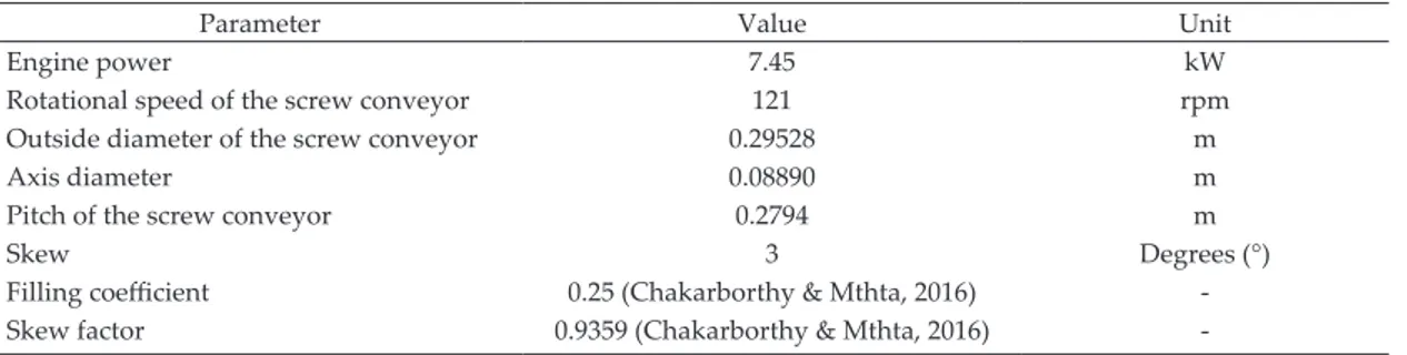
Table 1. Field data from the test system
Parameter Value Unit
Engine power 7.45 kW
Rotational speed of the screw conveyor 121 rpm
Outside diameter of the screw conveyor 0.29528 m
Axis diameter 0.08890 m
Pitch of the screw conveyor 0.2794 m
Skew 3 Degrees (°)
Filling coefficient 0.25 (Chakarborthy & Mthta, 2016)
-Skew factor 0.9359 (Chakarborthy & Mthta, 2016)
speed recommended in order for the system to work safely. The rotational speed analysis is presented by Goytisolo et al. (2001), using the following expression:
(3)min 30 rpm max 60 rpm
D D
w = → w =
where it is found that the minimum rotational speed of the system is wmin = 55rpm and the maximum is wmax = 110rpm. As presented in Goytisolo et al. (2001), it is not advisa-ble to exceed the maximum rotational speed for conve -ying high-density materials (as is the case for sea salt). Comparing this result with the information presented in Table 1, it can be seen that the current rotational speed is 10% over the maximum recommended, which can produce problems in the conveyor system, such as a fault due to twisting and shear stress, detachment of the screw, etc. It is therefore advisable to reduce rotatio -nal speed to within the estimated range.
Once the speed range for safely operating the sys -tem has been determined, an analysis is carried out for the power calculation, implementing the following ex -pressions:
H N ST
P P= +P +P (4)
367 H Q L
P = l (5)
20 N Q L
P = (6)
(sin( ) ) 367
ST Q L
P = φ (7)
where
PH = horizontal conveying capacity, with Q expressed
in Ton/hr
PN = power of the unloaded screw conveyor
PST = power necessary due to the skew of the conveyor
L = length of the axis between bearings
l = friction coefficient (with a value between 2.5 and 4 for the proposed system)
The power calculation performed in FMC Technologies (2013) considers that the screw conveyor is completely horizontal, and thus, the term PST = 0. However, imple
-menting the analytical developments presented in FMC Technologies (2013) and Gbasouzor & Owuana (2013), Equation (7) can be established, where ϕ is the skew angle of the screw conveyor. The parameters utilized for calculating the power of the conveyor system of in -terest are included in Table 2.
In this work, the material to be conveyed is salt with excess humidity, and therefore, λ=4. In addition, the to -tal length of the axis between bearings is L = 7.10mts. From Table 2, it can be seen that under the proposed working conditions, the total conveyor capacity is P = 2.0718kW. FMC Technologies (2013) recommends using a power correction factor of 42% of the calculated power so that the system can run smoothly P42% = 2.9419kW.
The screw conveyor analyzed has an attached belt drive system and a Model TXT 315 gear speed reducer. Thus, the efficiency of the conveyor system must be considered (hrans) and the calculated power corrected, resulting in
42%
req Trans
P P
h
= (8)
where it can be seen that hTrans= hRedutor hBandas.
As the transmission consists of a system of helical gears, belts, and pulleys, an efficiency of hTrans= 98.5% is estimated, coinciding with that reported by Richard & Keith (2012). Thus, a recommended power of Preq= 2.9867kW
is obtained. It is determined from the estimated power that the power implemented in the test system (see Ta -ble 1) is more than dou-ble the requirement.
Table 2. Test parameters and powers calculated for the analyzed salt conveyor system
Parameter Value Unit
L 7.10 m
l
4-φ 3 Degrees (°)
H
P 1.9416 kW
N
P 0.1048 kW
ST
stressAnAlysIsonAnAxIswIthfoursupports
sTressanalysisandmomenTdiagram
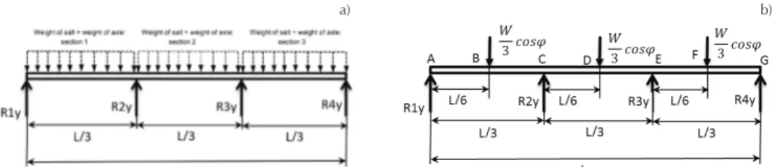
The free body diagram of the screw conveyor is prepa -red, as its four supports are in good condition. A hollow shaft of uniform diameter along its entire length is con-sidered for the static analysis, as presented in the Figu -re 2.
As it is a statically indeterminate system, the three-moment method is used, as presented by Ferdinand & Andrew (1982), to determine the reaction forces on each support, where the moments in the internal supports are given by
(9)
where, L1 = L2 =L3 = L/3 while the reaction forces are gi -ven by the following expressions:
(10)
1 1 2
3
2 1 2
2 2 2
( )
cos ( 2 ) cos
6 6
y y
R L L
M W W
R L L
L L L ϕ ϕ
+
= - + + + (11)
(12) 3 4 3 cos 6
y M W
R
L ϕ
= + (13)
Where W = Wsal + Weje represents the total weight, which
is numerically is W = 5.7291N. This weight represents the mass of the helix and the shaft (obtained through the use of a CAD tool), as well as the corresponding weight of the salt, considering that the trough has 80% of the capa -city total, as recommended in FMC Technologies (2013).
This is considered a three-degree skew angle. As the to -tal weight of the screw conveyor is 7.10m, it is clear that the reaction forces were R1y=667.4817N, R2y=2.1932E3N,
R3y=2.1932IE3N, and R4y=667.4817N.
The system shown in Figure 2 was also modeled using ANSYS® Finite Element software, with the aim of validating the analytical process utilized. The So -lid186 and Surf154 elements were used for modeling, with a total number of 28,256 elements and 197,952 no -des. This allowed determining that the reaction forces were R1y = 712.31N, R2y = 2.166 E3N, R3y = 2.040 E3N and
R4y = 802.15N, obtaining a respective difference of
6.29%, 1.25%, 7.42% ,and 16.00% for each reaction, com -pared analytically with the results.
During the operation of the conveyor system, the two most commonly generated faults are 1) the rupture of one or two supports and 2) the rupture of the screw conveyor shaft in the vicinity of the shaft section chan-ge (the same as are found near the supports). To deter -mine the moment diagram in each section of the system, the following expressions are used:
1
AB y
M =R x (14)
1 cos3 18cos
BC y
W LW
M =R - ϕx+ ϕ
(15)
(16)
2
1 2 cos3 2 3y 6 27cos
DE y y
R L
W LW
M =R - ϕ+R x+ - + ϕ
(17)
(18)
which is used to obtain the moment diagram along the screw conveyor, as shown in the following Figure 3.
In Figure 3, it can be seen that the movement values applied to the system are concentrated in the vicinity of
2 2
1 1 2
2 1 2 2
2 2
3 2 3 4
2 3
3 3
2( ) 24 24
2( ) 3 3
24 24
W cos L W cos L
M L L L
M L L L W cos L W cos L
ϕ ϕ ϕ ϕ -- - + = + - - 2 1 1 cos 6
y M W
R
L ϕ
= +
3y cos 1y 2y 4y
R =W ϕ-R -R -R
2
1 cos3 2 3y 18cos
CD y y
R L
W LW
M =R - ϕ+R x+ - + ϕ
2 3
1 2 3 2
2
2 cos 6 cos
3 3y 3y 27
EF y y y y
R L R L
W LW
M =R +R +R - ϕ+R x+ - - + ϕ
Figure 2. a) Salt distribution by sections, b) diagram of a screw conveyor with four supports
the supports. It is important to consider that a hollow constant-diameter shaft is used for the analytical deve-lopment.
StreSSdiStributionSalongtheaxiS
To know the integrity of the screw conveyor axis, the stress concentration is determined using rate-distortion theory and the von Mises method presented by Richard & Keith (2012). Considering flat stress-strain and a ho -llow shaft results in
1 2
2 2
4 4 4 4
32
32
'
3
(
EE In)
(
E E In)
d M
d T
d d
d d
σ
π
π
=
+
-
-
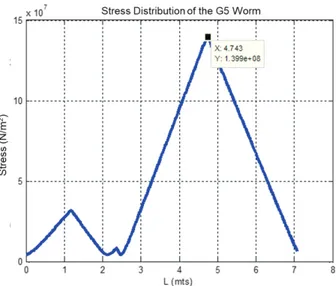
(19)The analytical calculation has a power of P=2.0719KW and an angular speed of 121 rpm, with which a constant torque of T=163.5139N-m is determined along the axis. The stress-strain diagram is obtained using Equation (19), as shown in Figure 4.
From the results obtained analytically, it is clear that the maximum vibration amplitude does not occur at the junction points where the intermediate supports are located; however, elevated peak stress-strains do occur. Considering 316 stainless steel for this case analysis, it can be seen that the safety factor considering the stress peak is F.S.=6.80, while through Finite Element, F.S.=6.94, representing a difference of 2.05% between the safety factor found analytically and that found through simulation. With these results, it can be seen that the shaft in these operating conditions presents no problem. Experimentally, however, there are condi -tions in which the system reaches the critical fault along the axis. In order to know the operating condition that causes the experimental fault, the case study for a frac
-ture in one of the intermediate supports is presented in the following section.
sTressanalysisonanaxiswiThThreesuPPorTs
ForceanalySiS, momentdiagram, andStreSS
According to the information provided by the com -pany, the equipment has had only one fault in its inter -mediate supports in 25 years of functioning. Therefore, the second case study is presented on a fault in one of the two intermediate supports, considering the dia -gram in Figure 5.
Using the double integration method for the deter -mination of this statically indeterminate system re-sults in
1 2 2 2 1 2
1 2 2
1 1 2 1
1
2 2 2 2
F F L L F L
R F R
L L L L
= - + + + + -
(20)
( )2 1 2 ( )2 ( )2 2 2 ( )2
2 1 1 2 2 2 1 2 1 2
1 2
1
4 L2 L2
R F L L L F L L L L
L L
= + - - + + - + -
(21)
1 1 2
3 2 2
1 2 1
1
2 2
L F L
R F R
L L L
= + + + -
(22)
Considering that F1= W/3 cosφ, F2= 2W/3 cosφ, the skew angle is 3 degrees, W=5.7291N, and the total length of the screw conveyor is 7.10 m, the reaction forces obtai -ned are R1=852.30N, R2=3038.92N, R3=1856.50N
As with the four-support case, the system shown in Figure 5 was modeled using ANSYS® Finite Element software and Solid 184 and Surface 154 elements, with a total number of 1,027 elements and 6,537 nodes, with
the purpose of revalidating the analytical process. For the numerical study, the estimated reaction forces were R1=729.57N, R2=3109.9N, and R3=1881.8N, obtaining a respective deviation of 16.82%, 2.28%, and 1.34% in re -lation to the results obtained analytically.
On the basis of the results obtained during the analysis, some interesting observations can be made re -garding what occurs when one of the supports in the screw conveyor fails, as presented in Figure 5. For the reaction in support R1y, with respect to the first case, there is a 27.69% increase in force and the direction has the same effect as the weight exerted by the salt and the axis. Support R2y shows an increase of 38.56%, while support R3y presents a decrease of 15.35%, considering the results obtained analytically.
The corresponding moment equations for the diffe -rent sections presented in Figure 5 are shown below:
1
AB
M =R x (23)
1 cos3 18cos
BC W LW
M =R - ϕx+ ϕ
(24)
(25)
(26)
(
)
21 cos 2 3 2cos
DE R L LW
M = R W- ϕ+R x+ - + ϕ
The moment diagram along the screw conveyor is obtai -ned using Equations (23) to (26), as shown in Figure 6.
In Figure 6, it can be seen that the maximum mo -ment occurs in the section where the missing support is located. Figure 7 is obtained using Equation (19) to cal -culate the stress distribution.
Considering the maximum stress presented in Figu -re 7, the-re is a safety factor of F.S.=1.23at the maximum
stress concentration point, which represents a decrease of 81.9% with respect to the safety factor when the screw conveyor works with all four supports. The Fini -te Element simulation analysis genera-tes a F.S. of 2.49, representing a difference of 102% with respect to the analytical analysis.
With the rupture of one of the internal supports in the screw conveyor axis, there is a 453.10% increase in the stress distributions in the region missing the sup -port, considering the results obtained with the analyti -cal expressions. The previous analysis cases consider a constant diameter hollow shaft when the 4 supports function correctly and the particular case where the rupture appears in one of the intermediate supports. There is no specific documented case of a rupture ap -pearing at either extreme of the supports.
An analytical solution can be obtained in simple structures such as uniform section beams or shafts; however, for complex structures, or in shafts with sec -tion changes, the use of numerical solu-tions such as the Finite Element Method is recommended to identify stress-concentrator areas. Neupane (2014) presents a comparative analysis between the analytical method and various Finite Element tools, such as ANSYS Work -bench 15.0, Creo Simulate 2.0, etc. The results from si -mulations under different classic beam examples present differences ranging from 4 to 16.6%, depending on the Finite Element tool used. A similar study was carried out by Ragbe (2016), which considered a section of uniform diameter tubing subjected to an internal pressure. The analytical results and ANSYS results were compared, obtaining a difference of 2.2%.
However, for the case of interest, in which there is a fault near a section change, analytical development does not allow knowing the stress concentrations in these concentrator areas necessitating the use of Finite Element. For this reason, the study was carried out ta -king these changes into consideration, as shown in the following Figure 8.
2
1 cos3 2 3 18cos
CD W R L LW
M =R - ϕ+R x + - + ϕ
Figure 5. a) Salt distribution with a fracture in the intermediate support, b) diagram of a screw conveyor with three supports
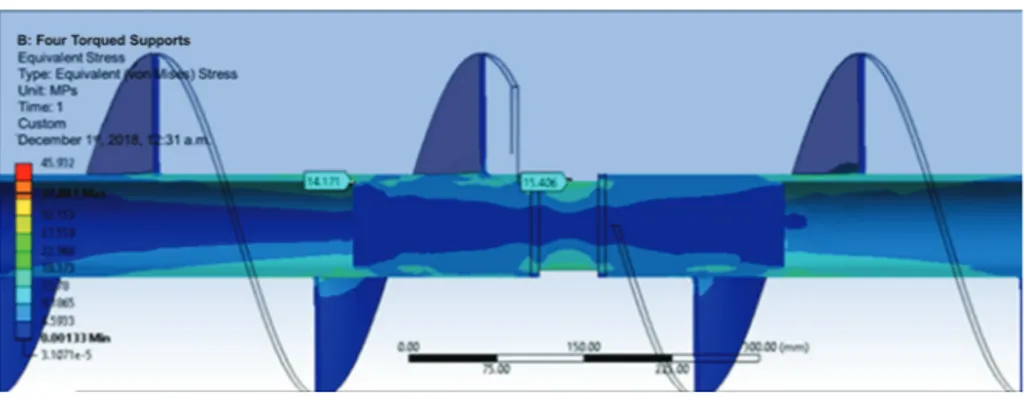
Based on the analytical results shown in Figures 4 and 7, the maximum stresses are found at the bushings. In addition, as can be seen in Figure 8, the section view of the screw conveyor shaft in the field shows a section of solid shaft coupled by welding to hollow sections. This drastic section change presents elevated stress concen -trations, a condition that must be analyzed numerica -lly. Figure 8 shows the stress concentration in the critical sections identified.
In Figure 9, stress concentrations can be seen in the vicinity of the section change; however, they are below the yield strength of the stainless steel, generating a safety factor of 11.18. Under these working conditions, the equipment presents no operational problems. The need to redesign for mechanical optimization of the equipment can even be established. Likewise, a second operating condition is analyzed numerically when a fault occurs during the operation corresponding to the
rupture of one of the intermediate supports (Figure 5), as presented below. For the case shown in Figure 9, the reaction forces obtained are the following: R1y=685.57N,
R2y=2553.20N, R3y=2128.50N, and R4y=653.99N, which re
-presents a difference of 2.63%, 2.66%, 3.03%, and 2.06%, respectively, with respect to the analytical result.
From the results obtained in Figure 10, a considera -ble increase (315.40%) can be seen in the stress concen -tration with respect to the behavior in Figure 9. This represents a safety factor of 2.68 - a 77.1% decrease in the F.S. Under this operating condition, there is a possi -bility of fault due to fatigue in the vicinity of the stress concentration. This condition is consistent with the in -formation provided by the company’s maintenance area regarding the shaft rupture when finding one of the bushings fractured. For the case shown in Figure 10, the reaction forces were the following: R1y=953.35N,
R2y=2851.1N and R3y=1942.7N, representing a difference
Figure 8. Section of solid axis in internal supports
from the analytical result of 10.54%, 6.58%, and 4.43%, respectively.
dIscussIons
The analytical case study of a hollow constant-diameter shaft presented in Figure 2 shows that when the separa -tion between intermediate supports is the same, the reaction forces at the extremes have the same numerical value, as do the intermediate supports.
However, when performing numerical modeling with the Finite Element tool, this pattern is not preser -ved. For the case analyzed, a difference of between 16.00 and 1.25% was found, which allows validating the results obtained through simulation for the four-sup -port case.
The second case study corresponds to the reaction force distribution across the supports when conside -ring a fracture in one of the intermediate elements in the ideal screw conveyor. For the simulated case, a di -fference was found in the range of 16.82-1.34%, valida -ting the procedure utilized for that particular case.
With the numerical modeling validated, the screw conveyor axis was analyzed, considering the screw along the shaft, as well as the variations in diameter
along its length. For the corresponding four-support case, a difference of 2.63%, 2.66%, 3.03%, and 2.06%, respectively, was obtained in each reaction, while for the second case study, there was a difference in reac -tions between the analytical and Finite Element methods of 10.54%, 6.58%, and 4.43%, respectively.
conclusIons
A piece of salt conveying equipment with a 25 ton/hr capacity has presented systematic problems for more than 20 years of operation on a salt production line in a regional company in the southern region of the state of Sonora, Mexico, with an annual capacity of 150,000 tons. This critical equipment generates unscheduled downtimes in the production line for up to 8 hours.
This work presents a methodology for the analytical study of a granular material conveyor system. For this, a mechanical study was carried out on the equipment presenting the greatest problem, conducting an analyti -cal study that allowed determining both the recom -mended theoretical conveyor capacity and axis speed, as well as the necessary power. The aforementioned analysis is commonly referenced in bibliographies found in the state of the art. However, no study allows Figure 9. Screw conveyor axis with four supports
identifying the problem presented in the equipment under study. Hence, this procedure is proposed to de -termine the reaction forces in the supports and the stress distributions along the screw conveyor. The stu -dy encompasses the functioning of the equipment im -mediately after maintenance and with the four supports in good condition, as well as the specific case of the failure of one of the intermediate supports.
However, the current analytical development pre -sents different limitations when considering complex sections during the analysis of a shaft with a non-uni -form section, as is the specific case study. In light of the above, a numerical study was carried out, implemen -ting the finite element analysis and obtaining the stress concentration at the critical points along the equipment when working with a full load. Validation of the analytical results through simulation is presented for the cases of screw conveyors with three supports and with four.
From the power analysis, it was found that the ne -cessary power is 60% lower than that currently insta -lled, corresponding to a 7.45 KW electric motor working at a speed of 1,800 rpm. On the other hand, the stress analysis along the axis for four supports (without con -sidering the screw in the screw conveyor shaft) allowed estimating a safety factor of 6.8 in the critical points near the supports. For the numerical case, it was obser -ved that when taking the screw into account, the sup -port load capacity is increased, achieving a safety factor of 11.6. This demonstrates that the screw generates a greater bending load capacity for the screw conveyor. In addition, Finite Element Analysis allows knowing the stress concentration at critical points of interest, such as where the fractures occur, according to infor -mation obtained from the company. Through this analysis, significant stress concentrations were found in the joint sections where the numerical intermediate supports with short sections of solid shaft are located, as presented in Figures 9 and 10. For the case with four supports, there was no fracture problem, even in the critical sections where maximum stress concentrations occur.
The equipment analyzed contains three salt mills in the upper part, located in the central part between sup -ports; however, a periodic tapping was observed in the chute and screw conveyor during the field study, due to the presence of considerably large rocks. This inter -mittent applied force generates sudden elevated stres -ses, although a safety factor of this magnitude does not represent a problem.
In the case study that considered a fracture in one of the intermediate supports (the section with the abrupt
section change), the stress concentration was increased by 341.2% with respect to the same simulation with four supports, obtaining a reduction of 77.3% in the safety factor, which coincides with the fault condition present in the shaft rupture. This allowed finding an elevated correlation between the maximum stress con -centration and element fracture, which in turn allowed issuing the recommendation to change the intermedia-te supports to avoid fracture and eliminaintermedia-te the pre -viously occurring fracture.
Finally, based on the results obtained, it is possible to establish the feasibility of the methodology presen -ted for the analysis of a granular material conveyor sys-tem based on the screw conveyor and have it be applicable to the redesign of the different salt conve -yors when the feeder in these systems is negligible.
Acknowledgements
This work was supported by the Technological Institute of Sonora, through the PROFAPI-2018 and PFCE 2018 projects.
references
Aguilar P.F. (1999). Análisis de la fuerza axial en un transportador
de sinfín. Journal de Ingeniería Mecánica, 1, 51-55.
Chakarborthy S. and Mthta A. (2016). Product design of semi flexible screw conveyor. Journal of Mechanical and Civil Engi-neering, 11(5). 10.9790/1684-11540113
FMC Technologies (2013). Link-belt Screw conveyor.
Engel B. and Sara S. H. (2017). Failure analysis and fatigue life es
-timation of a shaft of a rotary draw bending manchine. Inter-national Journal of Mechanical and Mechatronics Engineering,
11(11), 1785-1790. https://zenodo.org/badge/DOI/10.5281/ze
-nodo.1132685.svg
Ferdinand L.S. and Andrew P. (1982). Resistencia de materiales.
Ter-cera edición, Harla.
Gbasouzor A.I. and Owuana K.C. (2013). Design and characteriza
-tion of a model polythene recycling machine for economic development and pollution control in Nigeria. Proceedings of the World Congress on Engineering, London, U.K., july 3-5. Giraldo Q.R., Flores G.L., Higuera C.O. (2010). Diseño y construc
-ción de un mezclador de tornillo sinfín para mortero seco. Scientia et Technica, Año XVI, 45, 37-42. ISSN 0122-1701. Goytisolo E.R., Noa A.J., Fernández C.A. (2001). Análisis y solución
de avería del acoplamiento del sinfín de fondo de la bañera de una planta de plástico mixto. Journal Mecánica, 3, 79-85. Kursat H., Recep C., Gokhan K., Allan E.W., Mehmet U., Ibrahim
A. (2018). Finite element analysis of a PTO shaft used in an
Neupane D. (2014). Comparison of some FEM codes in static analysis. Bachelor thesis of University of Applied Sciences.
Recovered from: http://urn.fi/URN:NBN:fi:amk-201502092026 Ragbe M.A. (2016). Stresses analysis of pretroleum pipe finite ele
-ment under internal pressure. International Journal of Enginee-ring Research and Application, 6(8), ISSN: 2248-9622.
Richard B.G. and Keith N. (2012). Diseño en ingeniería mecánica.
Novena edición, Mc Graw Hill.
Xiaoming C. and David A.W. (2001). Finite element simulation of drive shaft in truck/suv frontal crash. International Technical Conference on Enhanced Safety of Vehicles. SAE INTERNA
-TIONAL.
Yu Y. and Arnold P.C. (1997). Theoretical modelling of torque re