G
Guuiimmaarrããeess--PPoorrttuuggaall
paper ID: 023 /p.1
Low frequency absorption by active control of impedance
P. Cobo, J. Pfretzschner, M. Cuesta, and A. Fernández
Instituto de Acústica, CSIC. Serrano 144, 28006 Madrid (Spain), iacpc24@ia.cetef.csic.es
ABSTRACT: Passive systems are inherently unable to provide absorption in the low frequency range due to limitations in the size-to-wavelength ratio. Active control systems, on the other hand, perform at low frequencies. A hybrid passive-active system can then be conceived which complements the low frequency range of a passive absorber with active control. When properly configured, such a hybrid system is able to afford broadband absorption.
1. INTRODUTION
An active control system can be combined with a conventional passive element to provide broadband absorption, including low frequencies [1-2]. The passive absorber may consist of a porous layer in front of an air cavity with an impervious end wall. The active system includes an error sensor, an actuator and an adaptive controller. If the error sensor is a microphone just behind the passive layer, the active system releases the pressure at the input of the air cavity [3]. This provides an active controller by pressure release. On the other hand, with two microphones in the air cavity and a deconvolution circuit, both the incident and the reflected components can be measured separately. An active system which cancels the reflected component in the air cavity is named an impedance matcher [4]. The performance of the active system depends upon the design of the passive element. Cobo et al. [5-6] demonstrated than active absorption by the impedance matching condition affords better results when the impedance of the passive element decreases. Otherwise, the pressure release condition performs better provided that the passive element is designed properly. Therefore, before implementing a hybrid passive-active absorption system it is worthy to predict its performance by means of an appropriate model.
This paper deals with the theoretical modelling and experimental validation of a hybrid passive-active absorption system with the pressure release condition. The passive element can be either a porous layer or a microperforated panel (MPP).
2. PLANE WAVE HYBRID ABSORPTION MODEL
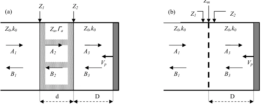
Let us consider a tube with plane waves propagating down and upstream. A primary source
somewhere on the left generates incident, Ai, and reflected, Bi, plane waves at each layer,
Figure 1. The passive absorber at the opposite side of the tube can be either a porous layer,
G
Guuiimmaarrããeess--PPoorrttuuggaall
paper ID: 023 /p.2
acoustic impedance Zm and thickness d, in front of an air cavity of thickness D. Let Z0 and k0
be the air characteristic acoustic impedance and wavenumber, respectively. For the active
[image:2.595.90.509.220.394.2]system, the end wall behind the air cavity is allowed to move rigidly with velocity Vp.
Figure 1 - Plane wave model for a hybrid passive-active system with a porous layer (a) or a MPP (b)
The absorption coefficient at the input of the absorber is
2
1− r
=
α , (1)
where 0 1 0 1 Z Z Z Z r + −
= , (2)
is the reflection coefficient,
( )
( )
( )
( )
MPP Z Z layer porous cosh cosh sinh cosh 2 m 2 2 1 ++ Γ Γ Γ + Γ= Z d Z d
d Z
d Z
Z
Z a a a
a a
a
a , (3)
is the input acoustic impedance to the passive layer, and
) sin( 2 ) cos( 2 0 0 3 0 0 0 3 0 0 2 D k e jB Z V D k e B Z V Z Z d jk p d jk p + +
= , (4)
D D d Z2 Vp Vp B3 A3 B3 A3 B1 A1 B1 A1
Z0,k0
Z0,k0
Z0,k0
Z0,k0
Z1
Z1 Z2
(a) (b)
Za,Γa
B2
A2
G
Guuiimmaarrããeess--PPoorrttuuggaall
paper ID: 023 /p.3
is the input impedance to the air cavity [5-6]. The porous layer can be modelled by [7]
) ( / ) (
2 f f K f
i
a = π ρ
Γ (5a)
) ( ) (f K f
Za = ρ , (5b)
where
[
2 1]
1/21144 . 0 0364 . 0 2 . 1 )
(f = + − E− −i E−
ρ (6a)
[
]
[
2 1]
1/2 2 / 1 1 2 9 . 24 82 . 2 17 . 21 9 . 24 82 . 2 64 . 29 101320 ) ( − − − − + + + + = E i E i E i E i fK , (6b)
and E=ρof/σ, σ being the flow resistivity of the porous material. The MPP, on the other hand,
is modelled by [8]
p t j pt x j x J j x j x J p d j
Zm 0
1
0 1
0 2 0.85
) ( ) ( 2
1 η ωρ
ωρ + + − − − − = −
, (7)
where η is the air viscosity coefficient (1.789 × 10 -5 kg/m⋅s), ω is the angular frequency,
ρ0 (1.21 kg/m3) is the air density, d is the panel thickness, t is the orifice diameter, p is the
perforation ratio of the MPP, and J0and J1are Bessel functions of the first kind of orders zero
and one, respectively. The perforate constant, x, is defined as
ω ρ η 0 4 d
x= . (8)
Equations (1-8) allow to calculate the absorption coefficient of a hybrid passive-active system as a function of frequency once the constitutive parameters of the passive material and the air
cavity thickness are known. For an active pressure-release control condition, Z2=0 [5-6].
G
Guuiimmaarrããeess--PPoorrttuuggaall
paper ID: 023 /p.4
AB SO R P T IO N C O E F F IC IEN T AB SO R P T IO N C O E F F IC IEN T AB SO R P T IO N C O E F F IC IEN T AB SO R P T IO N C O E F F IC IEN T
2 0 0 2 0 0 2 0 0
2 0 0 4 0 04 0 04 0 04 0 0 6 0 06 0 06 0 06 0 0 8 0 08 0 08 0 08 0 0 1 0 0 01 0 0 01 0 0 01 0 0 0 1 2 0 01 2 0 01 2 0 01 2 0 0 1 4 0 01 4 0 01 4 0 01 4 0 0 1 6 0 01 6 0 01 6 0 01 6 0 0 0
0 0 0 0 .2 0 .20 .2 0 .2 0 .4 0 .40 .4 0 .4 0 .6 0 .60 .6 0 .6 0 .8 0 .80 .8 0 .8 1 1 1 1
FR EQU EN C Y ( H z) FR EQU EN C Y ( H z) FR EQU EN C Y ( H z) FR EQU EN C Y ( H z) 2 0 0
2 0 0 2 0 0
2 0 0 4 0 04 0 04 0 04 0 0 6 0 06 0 06 0 06 0 0 8 0 08 0 08 0 08 0 0 1 0 0 01 0 0 01 0 0 01 0 0 0 1 2 0 01 2 0 01 2 0 01 2 0 0 1 4 0 01 4 0 01 4 0 01 4 0 0 1 6 0 01 6 0 01 6 0 01 6 0 0 0
0 0 0 0 .2 0 .20 .2 0 .2 0 .4 0 .40 .4 0 .4 0 .6 0 .60 .6 0 .6 0 .8 0 .80 .8 0 .8 1 1 1 1 (a) (b)
Figure 2 – Passive (solid line) and active (dotted line) absorption of a hybrid passive-active
system with (a) a foam layer with (σ, d, D)=(14000 N s m-4, 4 cm, 7 cm), or (b) a MPP with
(d, t, p, D)=(0.2 mm, 0.2 mm, 0.9 %, 7 cm)
3. EXPERIMENTAL SETUP
An experimental rig to measure the normal incidence hybrid passive-active absorption has been set at the Institute of Acoustic. This system, Figure 3, includes an aluminium tube, based upon a conventional standing wave tube, with length 1 m and diameter 10 cm, ended by the primary loudspeaker at one side, and the secondary loudspeaker at the opposite side.
G
Guuiimmaarrããeess--PPoorrttuuggaall
paper ID: 023 /p.5
[image:5.595.99.494.209.511.2]error signal. The user can configure the filter taps and the convergence factor of the adaptive filter, and the cutoff frequencies of the bandpass digital filter.
Figure 3 – Experimental rig for the hybrid passive-active absorption measurement
4. RESULTS
Figures 4 and 5 show experimental absorption results measured in the standing wave tube. In the first case, Figure 4, the passive element is a 4 cm melamine foam layer in front of a 4cm air gap. The passive system affords maximum absorption at 970 Hz. The active system, on the other hand, provides absorption close to 100 % below 500 Hz. Both the passive and active absorption curves intersect at 680 Hz. When the error signal of the active controller is filtered
with a lowpass 14th-order Butterworth filter, an average hybrid passive-active absorption of
0.97, in the frequency band from 100 Hz to 1600 Hz, is obtained.
G
Guuiimmaarrããeess--PPoorrttuuggaall
paper ID: 023 /p.6
FR EQU EN C Y (H z) FR EQU EN C Y (H z) FR EQU EN C Y (H z) FR EQU EN C Y (H z)
αααα
2 0 0 2 0 0 2 0 0
2 0 0 4 0 04 0 04 0 04 0 0 6 0 06 0 06 0 06 0 0 8 0 08 0 08 0 08 0 0 1 0 0 01 0 0 01 0 0 01 0 0 0 1 2 0 01 2 0 01 2 0 01 2 0 0 1 4 0 01 4 0 01 4 0 01 4 0 0 1 6 0 01 6 0 01 6 0 01 6 0 0 0
0 0 0 0 .2 0 .20 .2 0 .2 0 .4 0 .40 .4 0 .4 0 .6 0 .60 .6 0 .6 0 .8 0 .80 .8 0 .8 1 1 1 1
passive active
[image:6.595.90.508.108.484.2]hybrid passive-active
Figure 4 – Absorption coefficient of the hybrid passive-active system, using a porous as the
passive element, with (σ, d, D)=( 12000 N s m-4, 4 cm, 4 cm)
5. CONCLUSIONS
This paper has dealt with the feasibility of hybrid passive-active absorbers to provide broad frequency band absorption. In this type of absorber, a passive layer is placed in front of an air layer backed by an actively controlled actuator. Either a porous layer or a MPP has been used as the passive element. MPPs have advantages in being preferable in applications where hygiene is an issue, and allow compact hybrid absorbers to be constructed.
Using a plane-wave propagation model, the performance of two systems with different MPP parameters was predicted for the hybrid passive-active system.
G
Guuiimmaarrããeess--PPoorrttuuggaall
paper ID: 023 /p.7
FR EQU E N C Y ( H z) FR EQU E N C Y ( H z) FR EQU E N C Y ( H z) FR EQU E N C Y ( H z)
αααα
2 0 0 2 0 0 2 0 0
2 0 0 4 0 04 0 04 0 04 0 0 6 0 06 0 06 0 06 0 0 80 080 080 080 0 10 0 010 0 010 0 010 0 0 1 2 0 01 2 0 01 2 0 01 2 0 0 1 4 0 01 4 0 01 4 0 01 4 0 0 1 6 001 6 001 6 001 6 00 0
00 0 0 .2 0 .2 0 .2 0 .2 0 .4 0 .4 0 .4 0 .4 0 .6 0 .6 0 .6 0 .6 0 .8 0 .8 0 .8 0 .8 1 11 1
p a s s i ve p a s s i ve p a s s i ve p a s s i ve
h ybri d p a s s i ve -a cti ve h ybri d p a s s i ve -a cti ve h ybri d p a s s i ve -a cti ve h ybri d p a s s i ve -a cti ve a cti ve
[image:7.595.91.508.84.494.2]a cti ve a cti ve a cti ve
Figure 5 – Absorption coefficient of the hybrid passive-active, using a MPP as the passive element, with (d,t,p,D)=(0.13mm, 0.13mm, 0.5 %, 4.5 cm)
Experimental results were then finally presented for two hybrid passive-active systems. One of them uses a foam layer as the passive element and has a whole thickness of 8 cm. The other utilizes a thin MPP and is 4.5 cm thick. Average absorption coefficients of 0.97 and 0.82, in the frequency range from 100 Hz to 1600 Hz, are obtained with the first and second systems, respectively. The feasibility of designing hybrid passive-active absorbers with high absorption and reduced size has been demonstrated.
ACKNOWLEDGEMENT
G
Guuiimmaarrããeess--PPoorrttuuggaall
paper ID: 023 /p.8
REFERENCES
[1] Guicking, D. and Lorenz, E. (1984). “An active sound absorber with porous plate,” J. Vib.
Acoust. Stress Reliability Des., 106, 389-392.
[2] Guicking, D. and Karcher, K. (1984). “Active impedance control for one-dimensional
sound,” J. Vib. Acoust. Stress Reliability Des., 106, 393-396.
[3] Furstoss, M., Thenail, D., and Galland, M.A. (1997). “Surface impedance control for
sound absorption: direct and hybrid passive/active strategies,” J. Sound Vib., 203,
219-236.
[4] Beyene, S. and Burdisso, R.A. (1997). “A new hybrid passive/active noise absorption
system,” J. Acoust. Soc. Am., 101, 1512-1515.
[5] Cobo, P., Fernández, A., and Doutres, O. (2003). “Low frequency absorption using a
two-layer system with active control of input impedance,” J. Acoust. Soc. Am., 114,
3211-3216.
[6] Cobo, P., Pfretzschner, Cuesta, M., and Anthony, D.K. (2004). “Hybrid passive-active
absorption using microperforated panels,” J. Acoust. Soc. Am., accepted for publication.
[7] Allard, J.F. and Champoux, Y. (1992), “New empirical equations for sound propagation
in rigid frame fibrous materials”, J. Acoust. Soc. Am., 91, 3346-3353.
[8] Maa, D.Y. (1998). “Potential of microperforated panel absorber,” J. Acoust. Soc. Am.,